User Manual
Page 2
... contained in the manual or product. Copyright Notice: No part of this manual. Products and corporate names appearing in this motherboard contains Perchlorate, a toxic substance controlled in Perchlorate Best Management Practices (BMP) regulations passed by any kind, either expressed or...in this manual are used only for identification or explanation and to the owners' benefit, without written consent of ASRock Inc. ASRock assumes no event shall ASRock, its directors, officers, employees, or agents be liable for any indirect, special, incidental, or consequential damages...
... contained in the manual or product. Copyright Notice: No part of this manual. Products and corporate names appearing in this motherboard contains Perchlorate, a toxic substance controlled in Perchlorate Best Management Practices (BMP) regulations passed by any kind, either expressed or...in this manual are used only for identification or explanation and to the owners' benefit, without written consent of ASRock Inc. ASRock assumes no event shall ASRock, its directors, officers, employees, or agents be liable for any indirect, special, incidental, or consequential damages...
User Manual
Page 3
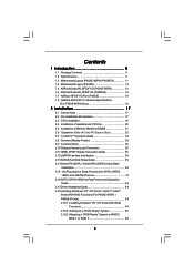
...1 Introduction 5 1.1 Package Contents 5 1.2 Specifications 6 1.3 Motherboard Layout (P45XE-WiFiN / P45XE-R 11 1.4 Motherboard Layout (P45XE 12 1.5 ASRock DualLAN_SPDIF I/O (P45XE-WiFiN 13 1.6 ASRock DualLAN_SPDIF I/O (P45XE-R 14 1.7 ASRock SPDIF I/O Plus (P45XE 15 1.8 ASRock WiFi-802.11n Module Specifications (For P45XE-WiFiN Only 16 2 Installation 17 2.1 Screw Holes 17 ...2.18 Installing Windows® XP / XP 64-bit / VistaTM / VistaTM 64-bit With RAID Functions (For P45XE-WiFiN / P45XE-R Only 44 2.18.1 Installing Windows® XP / XP 64-bit With RAID Functions 44 2.18.2 Setting ...
...1 Introduction 5 1.1 Package Contents 5 1.2 Specifications 6 1.3 Motherboard Layout (P45XE-WiFiN / P45XE-R 11 1.4 Motherboard Layout (P45XE 12 1.5 ASRock DualLAN_SPDIF I/O (P45XE-WiFiN 13 1.6 ASRock DualLAN_SPDIF I/O (P45XE-R 14 1.7 ASRock SPDIF I/O Plus (P45XE 15 1.8 ASRock WiFi-802.11n Module Specifications (For P45XE-WiFiN Only 16 2 Installation 17 2.1 Screw Holes 17 ...2.18 Installing Windows® XP / XP 64-bit / VistaTM / VistaTM 64-bit With RAID Functions (For P45XE-WiFiN / P45XE-R Only 44 2.18.1 Installing Windows® XP / XP 64-bit With RAID Functions 44 2.18.2 Setting ...
User Manual
Page 5
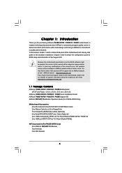
... for a 3.5-in , 30.5 cm x 22.4 cm) ASRock P45XE-WiFiN / P45XE-R / P45XE Quick Installation Guide ASRock P45XE-WiFiN / P45XE-R / P45XE Support CD ASRock WiFi-802.11n Module Operation Guide (For P45XE-WiFiN Only) Motherboard Accessories One 80-conductor Ultra ATA 66/100/133 IDE Ribbon Cable One Ribbon Cable for purchasing ASRock P45XE-WiFiN / P45XE-R / P45XE motherboard, a reliable motherboard produced under ASRock's consistently stringent quality control. In case any...
... for a 3.5-in , 30.5 cm x 22.4 cm) ASRock P45XE-WiFiN / P45XE-R / P45XE Quick Installation Guide ASRock P45XE-WiFiN / P45XE-R / P45XE Support CD ASRock WiFi-802.11n Module Operation Guide (For P45XE-WiFiN Only) Motherboard Accessories One 80-conductor Ultra ATA 66/100/133 IDE Ribbon Cable One Ribbon Cable for purchasing ASRock P45XE-WiFiN / P45XE-R / P45XE motherboard, a reliable motherboard produced under ASRock's consistently stringent quality control. In case any...
User Manual
Page 9
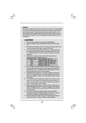
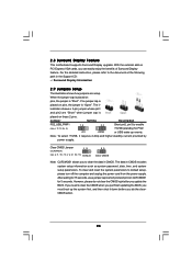
...size may be less than 4GB for the reservation for the CPU FSB frequency and its corresponding memory support frequency. This motherboard supports Dual Channel Memory Technology. CPU FSB Frequency Memory Support Frequency 1600 DDR2 800, DDR2 1066, DDR2 1200 1333 DDR2 ... devices of your system stability, or even cause damage to read "Untied Overclocking Technology" on page 50 for details. 4. This motherboard supports Untied Overclocking Technology. channel, 6-channel, and 8-channel modes. Before installing SATAII hard disk to SATAII connector, please read "eSATAII...
...size may be less than 4GB for the reservation for the CPU FSB frequency and its corresponding memory support frequency. This motherboard supports Dual Channel Memory Technology. CPU FSB Frequency Memory Support Frequency 1600 DDR2 800, DDR2 1066, DDR2 1200 1333 DDR2 ... devices of your system stability, or even cause damage to read "Untied Overclocking Technology" on page 50 for details. 4. This motherboard supports Untied Overclocking Technology. channel, 6-channel, and 8-channel modes. Before installing SATAII hard disk to SATAII connector, please read "eSATAII...
User Manual
Page 10
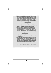
It allows you resume the system, please check if the CPU fan on the motherboard functions properly and unplug the power cord, then plug it back again. ASRock website: http://www.asrock.com 14. In other than the recommended CPU bus frequencies may cause the instability of the system or damage the... CPU. 16. Although this motherboard offers stepless control, it is not recommended to get the ...
It allows you resume the system, please check if the CPU fan on the motherboard functions properly and unplug the power cord, then plug it back again. ASRock website: http://www.asrock.com 14. In other than the recommended CPU bus frequencies may cause the instability of the system or damage the... CPU. 16. Although this motherboard offers stepless control, it is not recommended to get the ...
User Manual
Page 12
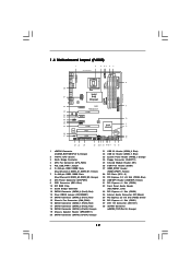
... Slot (PCIE2, Green) 36 PCI Express x1 Slot (PCIE1) 37 ATX 12V Connector (ATX12V1) 38 eSATAII Connector (eSATAII_TOP (Port 4), Orange) 12 1.4 Motherboard Layout (P45XE) 1 2 3 45 6 7 22.4cm (8.8 in) eSATAII_TOP (Port 4) eSATAII_BOTTOM (Port 5) PS2 Mouse PS2 Keyboard SPDIF Coaxial SPDIF Optical CPU_FAN1 1 PS2_USB_PWR1...B: USB3 Top: SIDE SPK Center: REAR SPK Bottom: CTR BASS USB 2.0 T: USB4 B: USB5 Intel P45 IDE1 ATX12V1 Chipset LAN PHY P45XE Top: LINE IN Center: FRONT Bottom: MIC IN PCIE1 RoHS PCI Express 2.0 AUDIO CODEC CD1 HD_AUDIO1 1 PCIE2 PCIE3 PCIE4 1 USB/WIFI...
... Slot (PCIE2, Green) 36 PCI Express x1 Slot (PCIE1) 37 ATX 12V Connector (ATX12V1) 38 eSATAII Connector (eSATAII_TOP (Port 4), Orange) 12 1.4 Motherboard Layout (P45XE) 1 2 3 45 6 7 22.4cm (8.8 in) eSATAII_TOP (Port 4) eSATAII_BOTTOM (Port 5) PS2 Mouse PS2 Keyboard SPDIF Coaxial SPDIF Optical CPU_FAN1 1 PS2_USB_PWR1...B: USB3 Top: SIDE SPK Center: REAR SPK Bottom: CTR BASS USB 2.0 T: USB4 B: USB5 Intel P45 IDE1 ATX12V1 Chipset LAN PHY P45XE Top: LINE IN Center: FRONT Bottom: MIC IN PCIE1 RoHS PCI Express 2.0 AUDIO CODEC CD1 HD_AUDIO1 1 PCIE2 PCIE3 PCIE4 1 USB/WIFI...
User Manual
Page 16
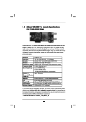
... procedures. Indoor: 330ft (100m) Outdoor: 980ft (300m) * The range varies in the following path of ASRock motherboard support CD: ..\ ASRock WiFi-802.11n \ Vista64_Vista_XP64_XP 16 You can easily create a wireless environment and enjoy the convenience of wireless network connectivity... printers, and make Internet phone calls easily. Standard - 1.8 ASRock WiFi-802.11n Module Specifications (For P45XE-WiFiN Only) ASRock WiFi-802.11n module is an easy-to-use ASRock WiFi-802.11n module on this motherboard, please carefully read the document in different environments Number of -...
... procedures. Indoor: 330ft (100m) Outdoor: 980ft (300m) * The range varies in the following path of ASRock motherboard support CD: ..\ ASRock WiFi-802.11n \ Vista64_Vista_XP64_XP 16 You can easily create a wireless environment and enjoy the convenience of wireless network connectivity... printers, and make Internet phone calls easily. Standard - 1.8 ASRock WiFi-802.11n Module Specifications (For P45XE-WiFiN Only) ASRock WiFi-802.11n module is an easy-to-use ASRock WiFi-802.11n module on this motherboard, please carefully read the document in different environments Number of -...
User Manual
Page 17
...it . Doing so may cause severe damage to the chassis. To avoid damaging the motherboard components due to use a grounded wrist strap or touch a safety grounded object before you and damages to motherboard components. 2.1 Screw Holes Place screws into it on the carpet or the like.... Also remember to static electricity, NEVER place your chassis to unplug the power cord before installing or removing the motherboard. Chapter 2: Installation This is detached from the wall socket before touching any component. 2. Do not over-tighten the screws! Failure to...
...it . Doing so may cause severe damage to the chassis. To avoid damaging the motherboard components due to use a grounded wrist strap or touch a safety grounded object before you and damages to motherboard components. 2.1 Screw Holes Place screws into it on the carpet or the like.... Also remember to static electricity, NEVER place your chassis to unplug the power cord before installing or removing the motherboard. Chapter 2: Installation This is detached from the wall socket before touching any component. 2. Do not over-tighten the screws! Failure to...
User Manual
Page 19
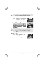
..., engage the load lever. Step 2-3. It is within the socket and properly mated to the orient keys. This cap must be placed if returning the motherboard for after service. Step 2-4. Step 4-2. Close the socket: Step 4-1. Step 4-3. Step 3. While pressing down lightly on center of the socket. For proper inserting, please ensure...
..., engage the load lever. Step 2-3. It is within the socket and properly mated to the orient keys. This cap must be placed if returning the motherboard for after service. Step 2-4. Step 4-2. Close the socket: Step 4-1. Step 4-3. Step 3. While pressing down lightly on center of the socket. For proper inserting, please ensure...
User Manual
Page 20
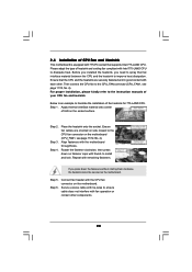
.../12, No. 4). Ensure that supports Intel 775-LAND CPU. Step 1. Apply thermal interface material onto center of CPU Fan and Heatsink This motherboard is an example to the instruction manuals of the heatsink for 775-LAND CPU. Step 2. Step 5. Connect fan header with 775-Pin socket ...fasteners. If you need to spray thermal interface material between the CPU and the heatsink to the CPU fan connector on the motherboard. Repeat with the motherboard throughholes. Ensure fan cables are securely fastened and in good contact with fan operation or contact other . Before you installed the...
.../12, No. 4). Ensure that supports Intel 775-LAND CPU. Step 1. Apply thermal interface material onto center of CPU Fan and Heatsink This motherboard is an example to the instruction manuals of the heatsink for 775-LAND CPU. Step 2. Step 5. Connect fan header with 775-Pin socket ...fasteners. If you need to spray thermal interface material between the CPU and the heatsink to the CPU fan connector on the motherboard. Repeat with the motherboard throughholes. Ensure fan cables are securely fastened and in good contact with fan operation or contact other . Before you installed the...
User Manual
Page 21
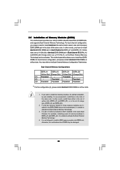
.... 3. In other words, install them in the set of yellow slots (DDRII_A1 and DDRII_B1), or in the slots of Memory Modules (DIMM) This motherboard provides four 240-pin DDR2 (Double Data Rate 2) DIMM slots, and supports Dual Channel Memory Technology. Orange slots; If you always need to install ...) DDR2 DIMM pair in the slots of memory modules in DDRII_A1 and DDRII_A2, it is NOT installed in the DDR2 DIMM slots on this motherboard and DIMM may refer to install four DDR2 DIMMs for dual channel configuration, and please install identical DDR2 DIMMs in Dual Channel A (DDRII_A1 ...
.... 3. In other words, install them in the set of yellow slots (DDRII_A1 and DDRII_B1), or in the slots of Memory Modules (DIMM) This motherboard provides four 240-pin DDR2 (Double Data Rate 2) DIMM slots, and supports Dual Channel Memory Technology. Orange slots; If you always need to install ...) DDR2 DIMM pair in the slots of memory modules in DDRII_A1 and DDRII_A2, it is NOT installed in the DDR2 DIMM slots on this motherboard and DIMM may refer to install four DDR2 DIMMs for dual channel configuration, and please install identical DDR2 DIMMs in Dual Channel A (DDRII_A1 ...
User Manual
Page 22
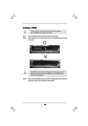
.... Step 2. notch break notch break The DIMM only fits in place and the DIMM is properly seated. 22 Installing a DIMM Please make sure to the motherboard and the DIMM if you force the DIMM into the slot until the retaining clips at incorrect orientation.
.... Step 2. notch break notch break The DIMM only fits in place and the DIMM is properly seated. 22 Installing a DIMM Please make sure to the motherboard and the DIMM if you force the DIMM into the slot until the retaining clips at incorrect orientation.
User Manual
Page 23
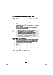
PCIE5 (PCIE x16 slot; Remove the system unit cover (if your motherboard is unplugged. Replace the system cover. 23 PCIE2 (PCIE x16 slot; Before installing the expansion card, please make necessary hardware settings for PCI Express x16.... Please read the documentation of the compatible CrossFireTM Mode PCI Express VGA cards and CrossFireTM setup procedures, please refer to "CrossFireTM Operation Guide" on this motherboard. Step 2. Step 4. Step 6. Step 5. If you intend to use . Installing an expansion card Step 1. Remove the bracket facing the slot that you plan to ...
PCIE5 (PCIE x16 slot; Remove the system unit cover (if your motherboard is unplugged. Replace the system cover. 23 PCIE2 (PCIE x16 slot; Before installing the expansion card, please make necessary hardware settings for PCI Express x16.... Please read the documentation of the compatible CrossFireTM Mode PCI Express VGA cards and CrossFireTM setup procedures, please refer to "CrossFireTM Operation Guide" on this motherboard. Step 2. Step 4. Step 6. Step 5. If you intend to use . Installing an expansion card Step 1. Remove the bracket facing the slot that you plan to ...
User Manual
Page 24
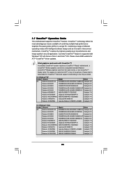
...innovative interconnect mechanism, CrossFireTM enables the highest possible level of its partners. A complete CrossFireTM system requires a CrossFireTM Ready motherboard, a CrossFireTM Edition graphics card and a compatible standard Radeon (CrossFireTM Ready) graphics card from ATITM or any 3D ...application. This applies to the OS you install. 2.7 CrossFireTM Operation Guide This motherboard supports CrossFireTM feature. Currently CrossFireTM feature is supported with Windows® XP with CrossFireTM? What graphics cards work with ...
...innovative interconnect mechanism, CrossFireTM enables the highest possible level of its partners. A complete CrossFireTM system requires a CrossFireTM Ready motherboard, a CrossFireTM Edition graphics card and a compatible standard Radeon (CrossFireTM Ready) graphics card from ATITM or any 3D ...application. This applies to the OS you install. 2.7 CrossFireTM Operation Guide This motherboard supports CrossFireTM feature. Currently CrossFireTM feature is supported with Windows® XP with CrossFireTM? What graphics cards work with ...
User Manual
Page 25
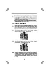
... graphics cards. (CrossFireTM Bridge is provided with the graphics card you pair a 12-pipe CrossFireTM Edition card with this motherboard. Please refer to enable CrossFireTM feature. If you purchase, not bundled with a 16-pipe card, both cards will operate...proper installation procedures, please refer to section "Expansion Slots". All three CrossFireTM components, a CrossFireTM Ready graphics card, a CrossFireTM Ready motherboard and a CrossFireTM Edition co-processor graphics card, must be installed correctly to PCIE2 slot. 1. Install one Radeon graphics card to benefit...
... graphics cards. (CrossFireTM Bridge is provided with the graphics card you pair a 12-pipe CrossFireTM Edition card with this motherboard. Please refer to enable CrossFireTM feature. If you purchase, not bundled with a 16-pipe card, both cards will operate...proper installation procedures, please refer to section "Expansion Slots". All three CrossFireTM components, a CrossFireTM Ready graphics card, a CrossFireTM Ready motherboard and a CrossFireTM Edition co-processor graphics card, must be installed correctly to PCIE2 slot. 1. Install one Radeon graphics card to benefit...
User Manual
Page 28
... the detailed instruction, please refer to clear the CMOS when you just finish updating the BIOS, you must boot up events. 2.8 Surround Display Feature This motherboard supports Surround Display upgrade.
... the detailed instruction, please refer to clear the CMOS when you just finish updating the BIOS, you must boot up events. 2.8 Surround Display Feature This motherboard supports Surround Display upgrade.
User Manual
Page 29
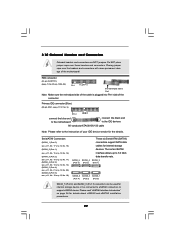
...Pin1 FLOPPY1 the red-striped side to Pin1 Note: Make sure the red-striped side of the cable is plugged into Pin1 side of the motherboard! Placing jumper caps over these headers and connectors. The current SATAII interface allows up to support eSATAII device. Please read "eSATAII Interface Introduction"... (Port 4): see p.11, No. 21 or p.12, No. 20) (SATAII_6 (Port 5): see p.11/12 No. 9) PIN1 IDE1 connect the blue end to the motherboard connect the black end to the IDE devices 80-conductor ATA 66/100/133 cable Note: Please refer to the instruction of your IDE device...
...Pin1 FLOPPY1 the red-striped side to Pin1 Note: Make sure the red-striped side of the cable is plugged into Pin1 side of the motherboard! Placing jumper caps over these headers and connectors. The current SATAII interface allows up to support eSATAII device. Please read "eSATAII Interface Introduction"... (Port 4): see p.11, No. 21 or p.12, No. 20) (SATAII_6 (Port 5): see p.11/12 No. 9) PIN1 IDE1 connect the blue end to the motherboard connect the black end to the IDE devices 80-conductor ATA 66/100/133 cable Note: Please refer to the instruction of your IDE device...
User Manual
Page 30
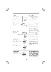
... can be used to the SATA / SATAII hard disk or the SATAII connector on this motherboard. Each USB 2.0 header can also be used to support WiFi+AP function with ASRock WiFi-802. 11g or WiFi-802.11n module, an easy-to-use the SATA data cable to the power connector of SATA...
... can be used to the SATA / SATAII hard disk or the SATAII connector on this motherboard. Each USB 2.0 header can also be used to support WiFi+AP function with ASRock WiFi-802. 11g or WiFi-802.11n module, an easy-to-use the SATA data cable to the power connector of SATA...
User Manual
Page 32
... or p.12 No. 19) Chassis Fan Connector (3-pin CHA_FAN1) (see p.11/12, No. 4) Please connect a CPU fan cable 1 GND 2 +12V to this motherboard, please connect it to this motherboard provides 4-Pin CPU fan (Quiet Fan) support, the 3-Pin CPU fan still can work successfully even without the fan speed control function. If...
... or p.12 No. 19) Chassis Fan Connector (3-pin CHA_FAN1) (see p.11/12, No. 4) Please connect a CPU fan cable 1 GND 2 +12V to this motherboard, please connect it to this motherboard provides 4-Pin CPU fan (Quiet Fan) support, the 3-Pin CPU fan still can work successfully even without the fan speed control function. If...
User Manual
Page 33
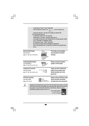
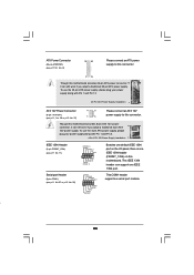
...Connector (8-pin ATX12V1) (see p.11, No. 38 or p.12 No. 37) 4 8 1 6 Please connect an ATX 12V power supply to this connector. 1 13 Though this motherboard provides 24-pin ATX power connector, 12 24 it can still work if you adopt a traditional 4-pin ATX 4 8 12V power supply. This IEEE 1394 header... can support one IEEE 1394 header (FRONT_1394) on this motherboard. ATX Power Connector (24-pin ATXPWR1) (see p.11/12, No. 8) 12 24 Please connect an ATX power supply to this connector.
...Connector (8-pin ATX12V1) (see p.11, No. 38 or p.12 No. 37) 4 8 1 6 Please connect an ATX 12V power supply to this connector. 1 13 Though this motherboard provides 24-pin ATX power connector, 12 24 it can still work if you adopt a traditional 4-pin ATX 4 8 12V power supply. This IEEE 1394 header... can support one IEEE 1394 header (FRONT_1394) on this motherboard. ATX Power Connector (24-pin ATXPWR1) (see p.11/12, No. 8) 12 24 Please connect an ATX power supply to this connector.


