
User Manual
Page 3
... / XP 64-bit Without RAID Functions 30 2.15.2 Installing Windows® VistaTM / VistaTM 64-bit Without RAID Functions 31 2.16 Untied Overclocking Technology 32 3 BIOS SETUP UTILITY 33 3.1 Introduction 33 3.1.1 BIOS Menu Bar 33 3.1.2 Navigation Keys 34 3.2 Main Screen 34 3.3 Smart Screen 35 3.4 Advanced Screen 36 3.4.1 CPU Configuration 36 3.4.2 Chipset Configuration 39 3
... / XP 64-bit Without RAID Functions 30 2.15.2 Installing Windows® VistaTM / VistaTM 64-bit Without RAID Functions 31 2.16 Untied Overclocking Technology 32 3 BIOS SETUP UTILITY 33 3.1 Introduction 33 3.1.1 BIOS Menu Bar 33 3.1.2 Navigation Keys 34 3.2 Main Screen 34 3.3 Smart Screen 35 3.4 Advanced Screen 36 3.4.1 CPU Configuration 36 3.4.2 Chipset Configuration 39 3

User Manual
Page 5
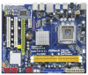
... specific information about the model you require technical support related to BIOS setup and information of the Support CD. www.asrock.com/support/index.asp 1.1 Package Contents ASRock P43ME Motherboard (Micro ATX Form Factor: 9.6-in x 8.3-in, 24.4 cm x 21.1 cm) ASRock P43ME Quick Installation Guide ASRock P43ME Support CD One 80-conductor Ultra ATA 66/100/133 IDE...
... specific information about the model you require technical support related to BIOS setup and information of the Support CD. www.asrock.com/support/index.asp 1.1 Package Contents ASRock P43ME Motherboard (Micro ATX Form Factor: 9.6-in x 8.3-in, 24.4 cm x 21.1 cm) ASRock P43ME Quick Installation Guide ASRock P43ME Support CD One 80-conductor Ultra ATA 66/100/133 IDE...

User Manual
Page 7
... CD - Boot Failure Guard (B.F.G.) Hardware - CPU Temperature Sensing Monitor - ACPI 1.1 Compliance Wake Up Events - CPU, VCCM, NB, VTT Voltage Multi-adjustment - ASRock Instant Flash (see CAUTION 9) BIOS Feature - 8Mb AMI BIOS - ASRock U-COP (see CAUTION 15) Certifications - Microsoft® Windows® 2000 / XP / XP 64-bit / VistaTM / VistaTM 64-bit compliant (see CAUTION 14...
... CD - Boot Failure Guard (B.F.G.) Hardware - CPU Temperature Sensing Monitor - ACPI 1.1 Compliance Wake Up Events - CPU, VCCM, NB, VTT Voltage Multi-adjustment - ASRock Instant Flash (see CAUTION 9) BIOS Feature - 8Mb AMI BIOS - ASRock U-COP (see CAUTION 15) Certifications - Microsoft® Windows® 2000 / XP / XP 64-bit / VistaTM / VistaTM 64-bit compliant (see CAUTION 14...

User Manual
Page 8
...DDR2 1200 * 1066 DDR2 667, DDR2 800, DDR2 1066 800 DDR2 667, DDR2 800 * DDR2 1200 memory modules will operate in the BIOS, applying Untied Overclocking Technology, or using the thirdparty overclocking tools. We are not responsible for the CPU FSB frequency and its corresponding memory support... frequency. WARNING Please realize that there is no need to adjust the BIOS option "DRAM Frequency" to page 19 for system usage under Microsoft® Windows® VistaTM 64-bit / VistaTM / XP 64-bit...
...DDR2 1200 * 1066 DDR2 667, DDR2 800, DDR2 1066 800 DDR2 667, DDR2 800 * DDR2 1200 memory modules will operate in the BIOS, applying Untied Overclocking Technology, or using the thirdparty overclocking tools. We are not responsible for the CPU FSB frequency and its corresponding memory support... frequency. WARNING Please realize that there is no need to adjust the BIOS option "DRAM Frequency" to page 19 for system usage under Microsoft® Windows® VistaTM 64-bit / VistaTM / XP 64-bit...

User Manual
Page 9
... utility, you to surveil your system by hardware monitor function and overclock your BIOS only in Flash ROM. To improve heat dissipation, remember to spray thermal grease between the CPU and the heatsink when you to access ASRock Instant Flash. ASRock Instant Flash is not supported under Windows® 2000. Please be noted...
... utility, you to surveil your system by hardware monitor function and overclock your BIOS only in Flash ROM. To improve heat dissipation, remember to spray thermal grease between the CPU and the heatsink when you to access ASRock Instant Flash. ASRock Instant Flash is not supported under Windows® 2000. Please be noted...

User Manual
Page 19
... FSB2 1_2 FSB3 1_2 Default If you want to overclock the memory module you need to clear the CMOS when you just finish updating the BIOS, you do not clear the CMOS right after you to short pin2 and pin3 on pins, the jumper is "Short". After waiting for PS/2 or... jumper is placed on this motherboard. Clear CMOS Jumper (CLRCMOS1) (see p.10 No. 32) 1_2 2_3 Default Clear CMOS Note: CLRCMOS1 allows you update the BIOS. When the jumper cap is placed on CLRCMOS1 for FSB3 jumper.
... FSB2 1_2 FSB3 1_2 Default If you want to overclock the memory module you need to clear the CMOS when you just finish updating the BIOS, you do not clear the CMOS right after you to short pin2 and pin3 on pins, the jumper is "Short". After waiting for PS/2 or... jumper is placed on this motherboard. Clear CMOS Jumper (CLRCMOS1) (see p.10 No. 32) 1_2 2_3 Default Clear CMOS Note: CLRCMOS1 allows you update the BIOS. When the jumper cap is placed on CLRCMOS1 for FSB3 jumper.

User Manual
Page 20
... face the problem, that DRAM frequency will beoverclocked very high. When you mount a FSB800 or FSB1066 CPU, and try to overclock to FSB1333 orFSB1600 (by BIOS setting) you may not work properly on this motherboard. Please refer to be strapped at higherfrequency, so the DRAM can work at lower frequency.
... face the problem, that DRAM frequency will beoverclocked very high. When you mount a FSB800 or FSB1066 CPU, and try to overclock to FSB1333 orFSB1600 (by BIOS setting) you may not work properly on this motherboard. Please refer to be strapped at higherfrequency, so the DRAM can work at lower frequency.

User Manual
Page 23
... for HD audio panel only. Connect Mic_IN (MIC) to Ground (GND). Please connect a CPU fan cable to this motherboard, please connect it to Pin 1-3. D. Enter BIOS Setup Utility. If you use AC'97 audio panel, please install it to the front panel audio header as below: A. Enter Advanced Settings, and then...
... for HD audio panel only. Connect Mic_IN (MIC) to Ground (GND). Please connect a CPU fan cable to this motherboard, please connect it to Pin 1-3. D. Enter BIOS Setup Utility. If you use AC'97 audio panel, please install it to the front panel audio header as below: A. Enter Advanced Settings, and then...

User Manual
Page 30
...ATA driver diskette [YN]?", press . Then, the drivers compatible to [AHCI]. Using SATA / SATAII HDDs with NCQ function STEP 1: Set Up BIOS. Insert the Support CD into the floppy drive. Please insert a floppy diskette into the floppy diskette. 30 Please select CD-ROM as ", ...auto-detected and listed on the support CD driver page. A. D. Please follow below steps. Start to install those required drivers. E. Enter BIOS SETUP UTILITY Advanced screen IDE Configuration. When you see these messages, Please insert a diskette into your optical drive to boot your SATA / ...
...ATA driver diskette [YN]?", press . Then, the drivers compatible to [AHCI]. Using SATA / SATAII HDDs with NCQ function STEP 1: Set Up BIOS. Insert the Support CD into the floppy drive. Please insert a floppy diskette into the floppy diskette. 30 Please select CD-ROM as ", ...auto-detected and listed on the support CD driver page. A. D. Please follow below steps. Start to install those required drivers. E. Enter BIOS SETUP UTILITY Advanced screen IDE Configuration. When you see these messages, Please insert a diskette into your optical drive to boot your SATA / ...

User Manual
Page 31
... SATA / SATAII HDDs with NCQ function STEP 1: Set Up BIOS. B. Insert the Windows® VistaTM / VistaTM 64-bit optical disk into the optical drive to boot your system, and follow below steps. page, please insert the ASRock Support CD into the optical drive again to [AHCI]. Intel&#... VistaTM 64-bit OS on your system. When prompted, insert the SATA / SATAII driver diskette containing the Intel® AHCI driver. A. Enter BIOS SETUP UTILITY Advanced screen IDE Configuration. Set "SATAII Configuration" to [Enhanced], and then in the option "Configure SATAII as ", please set the option...
... SATA / SATAII HDDs with NCQ function STEP 1: Set Up BIOS. B. Insert the Windows® VistaTM / VistaTM 64-bit optical disk into the optical drive to boot your system, and follow below steps. page, please insert the ASRock Support CD into the optical drive again to [AHCI]. Intel&#... VistaTM 64-bit OS on your system. When prompted, insert the SATA / SATAII driver diskette containing the Intel® AHCI driver. A. Enter BIOS SETUP UTILITY Advanced screen IDE Configuration. Set "SATAII Configuration" to [Enhanced], and then in the option "Configure SATAII as ", please set the option...

User Manual
Page 32
... VistaTM 64-bit OS on page 8 for the possible overclocking risk before you enable Untied Overclocking function, please enter "Overclock Mode" option of BIOS setup to set the option to [Enhanced], and then in the fixed mode so that FSB can operate under a more stable overclocking environment.... A. Set "SATAII Configuration" to [IDE]. Enter BIOS SETUP UTILITY Advanced screen IDE Configuration. Before you apply Untied Overclocking Technology. 32 Using SATA / SATAII HDDs without NCQ function STEP 1: Set up...
... VistaTM 64-bit OS on page 8 for the possible overclocking risk before you enable Untied Overclocking function, please enter "Overclock Mode" option of BIOS setup to set the option to [Enhanced], and then in the fixed mode so that FSB can operate under a more stable overclocking environment.... A. Set "SATAII Configuration" to [IDE]. Enter BIOS SETUP UTILITY Advanced screen IDE Configuration. Before you apply Untied Overclocking Technology. 32 Using SATA / SATAII HDDs without NCQ function STEP 1: Set up...

User Manual
Page 33
...top of the screen has a menu bar with its test routines. If you wish to configure your requirements Advanced To set up the advanced BIOS features H/W Monitor To display current hardware status Boot To set up the default system device to locate and load the Operating System Security To set...back on. Please press during the Power-On-Self-Test (POST) to get into the sub screen. 33 Because the BIOS software is constantly being updated, the following BIOS setup screens and descriptions are for reference purpose only, and they may not exactly match what you start up the system ...
...top of the screen has a menu bar with its test routines. If you wish to configure your requirements Advanced To set up the advanced BIOS features H/W Monitor To display current hardware status Boot To set up the default system device to locate and load the Operating System Security To set...back on. Please press during the Power-On-Self-Test (POST) to get into the sub screen. 33 Because the BIOS software is constantly being updated, the following BIOS setup screens and descriptions are for reference purpose only, and they may not exactly match what you start up the system ...

User Manual
Page 34
... the selected screen To display the General Help Screen To load optimal default values for the function description of each navigation key. BIOS SETUP UTILITY Main Smart Advanced H/W Monitor Boot Security Exit System Overview System Time System Date [14:00:09] [Mon 04/27/2009...] BIOS Version : P43ME P1.00 Processor Type : Intel (R) CPU 3.00GHz Processor Speed : 3000MHz Microcode Update : F34/17 Cache Size : 1024KB Total Memory DDRII_A1 DDRII_B1 : 512MB ...
... the selected screen To display the General Help Screen To load optimal default values for the function description of each navigation key. BIOS SETUP UTILITY Main Smart Advanced H/W Monitor Boot Security Exit System Overview System Time System Date [14:00:09] [Mon 04/27/2009...] BIOS Version : P43ME P1.00 Processor Type : Intel (R) CPU 3.00GHz Processor Speed : 3000MHz Microcode Update : F34/17 Cache Size : 1024KB Total Memory DDRII_A1 DDRII_B1 : 512MB ...

User Manual
Page 35
... this operation. Load Power Saving Setup Default Load power saving setup default. If you can be used for this option, it will 35 ASRock Instant Flash ASRock Instant Flash is a BIOS flash utility embedded in a few clicks without entering operating systems first like MS-DOS or Windows®. Just launch this operation. Load...
... this operation. Load Power Saving Setup Default Load power saving setup default. If you can be used for this option, it will 35 ASRock Instant Flash ASRock Instant Flash is a BIOS flash utility embedded in a few clicks without entering operating systems first like MS-DOS or Windows®. Just launch this operation. Load...

User Manual
Page 36
...Configuration PCIPnP Configuration Floppy Configuration SuperIO Configuration USB Configuration Overclock Settings Select Screen Select Item Enter Go to malfunction. 3.4.1 CPU Configuration BIOS SETUP UTILITY Advanced CPU Configuration Overclock Mode CPU Frequency (MHz) PCIE Frequency (MHz) Boot Failure Guard Spread Spectrum [Auto]..., American Megatrends, Inc. 36 Setting wrong values in below sections may cause system to update your BIOS, and reboot your system after BIOS update process completes. 3.4 Advanced Screen In this section may set the configurations for the following items:...
...Configuration PCIPnP Configuration Floppy Configuration SuperIO Configuration USB Configuration Overclock Settings Select Screen Select Item Enter Go to malfunction. 3.4.1 CPU Configuration BIOS SETUP UTILITY Advanced CPU Configuration Overclock Mode CPU Frequency (MHz) PCIE Frequency (MHz) Boot Failure Guard Spread Spectrum [Auto]..., American Megatrends, Inc. 36 Setting wrong values in below sections may cause system to update your BIOS, and reboot your system after BIOS update process completes. 3.4 Advanced Screen In this section may set the configurations for the following items:...

User Manual
Page 39
DRAM Timing Configuation BIOS SETUP UTILITY Advanced Standard Memory Settings Standard Memory Settings : 5-5-5-15-36-5-3-3-3 DRAM tCL [Auto] DRAM tRCD [Auto] DRAM tRP [Auto] DRAM tRAS [Auto] DRAM tRFC... Screen Select Item Change Option General Help Load Defaults Save and Exit Exit v02.54 (C) Copyright 1985-2005, American Megatrends, Inc. Max: 7. 3.4.2 Chipset Configuration BIOS SETUP UTILITY Advanced Chipset Settings DRAM Frequency Flexibility Option [Auto] [Disabled] DRAM Timing Configuration DRAM RCOMP and tRD Configuration DRAM DLL SKEW Configuration Voltage Configuration...
DRAM Timing Configuation BIOS SETUP UTILITY Advanced Standard Memory Settings Standard Memory Settings : 5-5-5-15-36-5-3-3-3 DRAM tCL [Auto] DRAM tRCD [Auto] DRAM tRP [Auto] DRAM tRAS [Auto] DRAM tRFC... Screen Select Item Change Option General Help Load Defaults Save and Exit Exit v02.54 (C) Copyright 1985-2005, American Megatrends, Inc. Max: 7. 3.4.2 Chipset Configuration BIOS SETUP UTILITY Advanced Chipset Settings DRAM Frequency Flexibility Option [Auto] [Disabled] DRAM Timing Configuration DRAM RCOMP and tRD Configuration DRAM DLL SKEW Configuration Voltage Configuration...

User Manual
Page 40
... This controls the number of DRAM clocks for TRFC. DRAM tRRD This controls the number of DRAM clocks for TRCD. DRAM RCOMP and tRD Configuration BIOS SETUP UTILITY Advanced DRAM RCOMP Settings DRAM CH0 RCOMP Settings : 18-0-10-7-7-7-7 DRAM CH0 RCOMP ODT [Auto] DRAM CH0 G0 (Data) [Auto] DRAM CH0 G1...
... This controls the number of DRAM clocks for TRFC. DRAM tRRD This controls the number of DRAM clocks for TRCD. DRAM RCOMP and tRD Configuration BIOS SETUP UTILITY Advanced DRAM RCOMP Settings DRAM CH0 RCOMP Settings : 18-0-10-7-7-7-7 DRAM CH0 RCOMP ODT [Auto] DRAM CH0 G0 (Data) [Auto] DRAM CH0 G1...

User Manual
Page 42
...] and [Normal]. The default value is [Auto]. 42 DRAM CH0 CLKSET1 SKEW This controls the number of DRAM CH0 tRD. Min: 0. DRAM DLL SKEW Settings BIOS SETUP UTILITY Advanced DRAM DLL SKEW Settings DRAM CH0 CLKSET0 SKEW Info:13-0-1-0-0-1300 DRAM CH0 CLKSET0 SKEW [Auto] DRAM CH0 CLKSET1 SKEW Info:13...
...] and [Normal]. The default value is [Auto]. 42 DRAM CH0 CLKSET1 SKEW This controls the number of DRAM CH0 tRD. Min: 0. DRAM DLL SKEW Settings BIOS SETUP UTILITY Advanced DRAM DLL SKEW Settings DRAM CH0 CLKSET0 SKEW Info:13-0-1-0-0-1300 DRAM CH0 CLKSET0 SKEW [Auto] DRAM CH0 CLKSET1 SKEW Info:13...

User Manual
Page 44
...]. The default value is [Auto]. Configuration options: [Auto], [1.11V], [1.21V], [1.30V] and [1.40V]. SB 1.1V Voltage Use this to select SB 1.1V Voltage. Voltage Settings BIOS SETUP UTILITY Advanced Voltage Settings Vcore : 1.360V CPU Voltage [Auto] DRAM Voltage : 1.90V DRAM Voltage : [Auto] Voltage Settings : 0.63Vtt-1.11V-1.52V-1.11V-1.10V GTLRef Voltage...
...]. The default value is [Auto]. Configuration options: [Auto], [1.11V], [1.21V], [1.30V] and [1.40V]. SB 1.1V Voltage Use this to select SB 1.1V Voltage. Voltage Settings BIOS SETUP UTILITY Advanced Voltage Settings Vcore : 1.360V CPU Voltage [Auto] DRAM Voltage : 1.90V DRAM Voltage : [Auto] Voltage Settings : 0.63Vtt-1.11V-1.52V-1.11V-1.10V GTLRef Voltage...

User Manual
Page 45
Configuration options: [Auto], [Enabled] and [Disabled]. Besides the BIOS option, you can also choose our Intelligent Energy Saver utility to [Enabled]. If you select [Auto], the onboard HD Audio will be disabled when PCI ...
Configuration options: [Auto], [Enabled] and [Disabled]. Besides the BIOS option, you can also choose our Intelligent Energy Saver utility to [Enabled]. If you select [Auto], the onboard HD Audio will be disabled when PCI ...


