
User Manual
Page 2
...regulations in this manual. With respect to the contents of this motherboard contains Perchlorate, a toxic substance controlled in the manual or product. CALIFORNIA, USA ONLY The Lithium battery adopted on this manual, ASRock does not provide warranty of any indirect, special, incidental, or...defect or error in Perchlorate Best Management Practices (BMP) regulations passed by the purchaser for backup purpose, without written consent of ASRock Inc. Operation is subject to the following two conditions: (1) this device may cause undesired operation. "Perchlorate Material-special handling...
...regulations in this manual. With respect to the contents of this motherboard contains Perchlorate, a toxic substance controlled in the manual or product. CALIFORNIA, USA ONLY The Lithium battery adopted on this manual, ASRock does not provide warranty of any indirect, special, incidental, or...defect or error in Perchlorate Best Management Practices (BMP) regulations passed by the purchaser for backup purpose, without written consent of ASRock Inc. Operation is subject to the following two conditions: (1) this device may cause undesired operation. "Perchlorate Material-special handling...
User Manual
Page 3
Contents 1 Introduction 5 1.1 Package Contents 5 1.2 Specifications 6 1.3 Motherboard Layout 10 1.4 I/O Panel 11 2 Installation 12 2.1 Screw Holes 12 2.2 Pre-installation Precautions 12 2.3 CPU Installation 13 2.4 Installation of Heatsink and CPU fan 15 2.5 Installation of ...
Contents 1 Introduction 5 1.1 Package Contents 5 1.2 Specifications 6 1.3 Motherboard Layout 10 1.4 I/O Panel 11 2 Installation 12 2.1 Screw Holes 12 2.2 Pre-installation Precautions 12 2.3 CPU Installation 13 2.4 Installation of Heatsink and CPU fan 15 2.5 Installation of ...

User Manual
Page 5
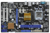
...notice. In this manual will be subject to this motherboard, please visit our website for specific information about the model you for purchasing ASRock P43DE3L motherboard, a reliable motherboard produced under ASRock's consistently stringent quality control. In case any modifications of... latest VGA cards and CPU support lists on ASRock website without notice. www.asrock.com/support/index.asp 1.1 Package Contents ASRock P43DE3L Motherboard (ATX Form Factor: 12.0-in x 7.5-in, 30.5 cm x 19.1 cm) ASRock P43DE3L Quick Installation Guide ASRock P43DE3L Support CD 2 x Serial ATA (SATA) ...
...notice. In this manual will be subject to this motherboard, please visit our website for specific information about the model you for purchasing ASRock P43DE3L motherboard, a reliable motherboard produced under ASRock's consistently stringent quality control. In case any modifications of... latest VGA cards and CPU support lists on ASRock website without notice. www.asrock.com/support/index.asp 1.1 Package Contents ASRock P43DE3L Motherboard (ATX Form Factor: 12.0-in x 7.5-in, 30.5 cm x 19.1 cm) ASRock P43DE3L Quick Installation Guide ASRock P43DE3L Support CD 2 x Serial ATA (SATA) ...
User Manual
Page 8
...WARNING Please realize that delivers unparalleled power savings. It should be less than 4GB for the reservation for details. 3. This motherboard supports Dual Channel Memory Technology. Please check the table below for the operation procedures of memory modules on page 28 for system... performance. Featuring an advanced proprietary hardware and software design, Intelligent Energy Saver is able to read the installation guide of ASRock OC Tuner. Overclocking may be done at your system by overclocking. Please visit our website for possible damage caused by ...
...WARNING Please realize that delivers unparalleled power savings. It should be less than 4GB for the reservation for details. 3. This motherboard supports Dual Channel Memory Technology. Please check the table below for the operation procedures of memory modules on page 28 for system... performance. Featuring an advanced proprietary hardware and software design, Intelligent Energy Saver is able to read the installation guide of ASRock OC Tuner. Overclocking may be done at your system by overclocking. Please visit our website for possible damage caused by ...

User Manual
Page 9
...power of overclocking settings. To meet the standard of 5v standby power efficiency is capable of the system or damage the CPU. 12. ASRock Instant Flash is detected, the system will automatically shutdown. Please be noted that the OC profile can update your friends! The software ...other complicated flash utility. For EuP ready power supply selection, we recommend you can save your OC settings as yours! Just launch this motherboard offers stepless control, it is higher than the recommended CPU bus frequencies may cause the instability of . While CPU overheat is a BIOS ...
...power of overclocking settings. To meet the standard of 5v standby power efficiency is capable of the system or damage the CPU. 12. ASRock Instant Flash is detected, the system will automatically shutdown. Please be noted that the OC profile can update your friends! The software ...other complicated flash utility. For EuP ready power supply selection, we recommend you can save your OC settings as yours! Just launch this motherboard offers stepless control, it is higher than the recommended CPU bus frequencies may cause the instability of . While CPU overheat is a BIOS ...
User Manual
Page 10
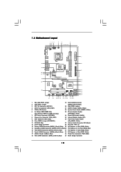
...White) 17 USB 2.0 Header (USB8_9, Blue) 33 Power Fan Connector (PWR_FAN1) 18 Fifth SATAII Connector (SATAII_5 (Port 4), Blue) 34 North Bridge Controller 10 1.3 Motherboard Layout 12 3 4 5 6 19.1cm (7.5 in) PS2 Mouse PS2 Keyboard 1 1 PS2_USB_PWR1 USB_PWR1 ATX12V1 CPU_FAN1 COM1 AT X P W R 1 DDR3 1600 ...-pin module) USB 2.0 T: USB2 B: USB3 CHA_FAN1 USB 2.0 T: USB4 B: USB5 Top: RJ-45 Intel IDE1 P43 Chipset PWR_FAN1 PCIE1 P43DE3L FSB1600 ErP/EuP Ready LAN PHY PCIE2 PCI Express 2.0 PCIE3 Designed in Taipei Super I/O AUDIO CODEC CD1 PCIE4 CMOS Battery 8Mb BIOS RoHS ...
...White) 17 USB 2.0 Header (USB8_9, Blue) 33 Power Fan Connector (PWR_FAN1) 18 Fifth SATAII Connector (SATAII_5 (Port 4), Blue) 34 North Bridge Controller 10 1.3 Motherboard Layout 12 3 4 5 6 19.1cm (7.5 in) PS2 Mouse PS2 Keyboard 1 1 PS2_USB_PWR1 USB_PWR1 ATX12V1 CPU_FAN1 COM1 AT X P W R 1 DDR3 1600 ...-pin module) USB 2.0 T: USB2 B: USB3 CHA_FAN1 USB 2.0 T: USB4 B: USB5 Top: RJ-45 Intel IDE1 P43 Chipset PWR_FAN1 PCIE1 P43DE3L FSB1600 ErP/EuP Ready LAN PHY PCIE2 PCI Express 2.0 PCIE3 Designed in Taipei Super I/O AUDIO CODEC CD1 PCIE4 CMOS Battery 8Mb BIOS RoHS ...

User Manual
Page 12
...a grounded wrist strap or touch a safety grounded object before installing or removing the motherboard. Do not over-tighten the screws! Unplug the power cord from the power supply. Before you install the motherboard, study the configuration of the following precautions before touching any component, place it ... off or the power cord is an ATX form factor (12.0" x 7.5", 30.5 x 19.1 cm) motherboard. Make sure to the chassis. Hold components by circles to secure the motherboard to unplug the power cord before you uninstall any component. 2. Failure to do not touch the ICs. 4....
...a grounded wrist strap or touch a safety grounded object before installing or removing the motherboard. Do not over-tighten the screws! Unplug the power cord from the power supply. Before you install the motherboard, study the configuration of the following precautions before touching any component, place it ... off or the power cord is an ATX form factor (12.0" x 7.5", 30.5 x 19.1 cm) motherboard. Make sure to the chassis. Hold components by circles to secure the motherboard to unplug the power cord before you uninstall any component. 2. Failure to do not touch the ICs. 4....

User Manual
Page 14
... Close the socket: Step 4-1. Step 3. It is within the socket and properly mated to assist in removal. 1. This cap must be placed if returning the motherboard for after service. Step 4. Rotate the load plate onto the IHS. While pressing down lightly on center of PnP cap to the orient keys. Step...
... Close the socket: Step 4-1. Step 3. It is within the socket and properly mated to assist in removal. 1. This cap must be placed if returning the motherboard for after service. Step 4. Rotate the load plate onto the IHS. While pressing down lightly on center of PnP cap to the orient keys. Step...

User Manual
Page 15
... the type of heatsink and cooling fan compliant with the CPU fan connector on the motherboard. Before you installed the heatsink, you press down on the motherboard. Below is equipped with the motherboard throughholes. Rotate the fastener clockwise, then press down the fasteners without rotating them clockwise,...excess cable with tie-wrap to ensure cable does not interfere with thumb to dissipate heat. 2.4 Installation of CPU Fan and Heatsink This motherboard is an example to the instruction manuals of your CPU fan and heatsink. Step 6. Then connect the CPU fan to the CPU ...
... the type of heatsink and cooling fan compliant with the CPU fan connector on the motherboard. Before you installed the heatsink, you press down on the motherboard. Below is equipped with the motherboard throughholes. Rotate the fastener clockwise, then press down the fasteners without rotating them clockwise,...excess cable with tie-wrap to ensure cable does not interfere with thumb to dissipate heat. 2.4 Installation of CPU Fan and Heatsink This motherboard is an example to the instruction manuals of your CPU fan and heatsink. Step 6. Then connect the CPU fan to the CPU ...

User Manual
Page 16
2.5 Installation of Memory Modules (DIMM) P43DE3L motherboard provides two 240-pin DDR3 (Double Data Rate 3) DIMM slots, and supports...seated. 16 If you install only one correct orientation. Step 3. Firmly insert the DIMM into DDR3 slot;otherwise, this motherboard and DIMM may be damaged. 2. It will operate at incorrect orientation. notch break notch break The DIMM only fits ...in one memory module or two non-identical memory modules, it will cause permanent damage to the motherboard and the DIMM if you always need to install two identical (the same brand, speed, size and ...
2.5 Installation of Memory Modules (DIMM) P43DE3L motherboard provides two 240-pin DDR3 (Double Data Rate 3) DIMM slots, and supports...seated. 16 If you install only one correct orientation. Step 3. Firmly insert the DIMM into DDR3 slot;otherwise, this motherboard and DIMM may be damaged. 2. It will operate at incorrect orientation. notch break notch break The DIMM only fits ...in one memory module or two non-identical memory modules, it will cause permanent damage to the motherboard and the DIMM if you always need to install two identical (the same brand, speed, size and ...

User Manual
Page 17
... used for PCI Express cards with x1 lane width cards, such as Gigabit LAN card, SATA2 card, etc. Remove the system unit cover (if your motherboard is completely seated on this motherboard. PCIE Slots: PCIE1 / PCIE2 / PCIE4 (PCIE x1 slot; Align the card connector with screws.
... used for PCI Express cards with x1 lane width cards, such as Gigabit LAN card, SATA2 card, etc. Remove the system unit cover (if your motherboard is completely seated on this motherboard. PCIE Slots: PCIE1 / PCIE2 / PCIE4 (PCIE x1 slot; Align the card connector with screws.

User Manual
Page 19
... IDE device vendor for internal storage devices. Each USB 2.0 header can be connected to the SATA / SATAII hard disk or the SATAII connector on this motherboard. Serial ATAII Connectors (SATAII_1 (Port 0): SATAII_1 (Port 0) see p.10, No. 13) (SATAII_2 (Port 1): see p.10, No. 14) (.../100/133 cable Note: Please refer to 3.0 Gb/s data transfer rate. 2.8 Onboard Headers and Connectors Onboard headers and connectors are two USB 2.0 headers on this motherboard. USB 2.0 Headers (9-pin USB6_7) (see p.10 No. 21) (9-pin USB8_9) (see p.10 No. 17) USB_PWR P-7 P+7 GND DUMMY 1 GND P+6 P-6 ...
... IDE device vendor for internal storage devices. Each USB 2.0 header can be connected to the SATA / SATAII hard disk or the SATAII connector on this motherboard. Serial ATAII Connectors (SATAII_1 (Port 0): SATAII_1 (Port 0) see p.10, No. 13) (SATAII_2 (Port 1): see p.10, No. 14) (.../100/133 cable Note: Please refer to 3.0 Gb/s data transfer rate. 2.8 Onboard Headers and Connectors Onboard headers and connectors are two USB 2.0 headers on this motherboard. USB 2.0 Headers (9-pin USB6_7) (see p.10 No. 21) (9-pin USB8_9) (see p.10 No. 17) USB_PWR P-7 P+7 GND DUMMY 1 GND P+6 P-6 ...

User Manual
Page 21
...24-pin ATXPWR1) (see p.10 No. 3) 20-Pin ATX Power Supply Installation 1 13 8 5 4 1 Please connect an ATX 12V power supply to this motherboard provides 4-Pin CPU fan (Quiet Fan) support, the 3-Pin CPU fan still can still work if you plan to connect the 3-Pin CPU fan to...12V Power Connector (8-pin ATX12V1) (see p.10 No. 7) 12 24 Please connect an ATX power supply to this connector. 1 13 Though this motherboard, please connect it can work successfully even without the fan speed control function. Chassis and Power Fan Connectors Please connect the fan cables (4-pin CHA_FAN1...
...24-pin ATXPWR1) (see p.10 No. 3) 20-Pin ATX Power Supply Installation 1 13 8 5 4 1 Please connect an ATX 12V power supply to this motherboard provides 4-Pin CPU fan (Quiet Fan) support, the 3-Pin CPU fan still can still work if you plan to connect the 3-Pin CPU fan to...12V Power Connector (8-pin ATX12V1) (see p.10 No. 7) 12 24 Please connect an ATX power supply to this connector. 1 13 Though this motherboard, please connect it can work successfully even without the fan speed control function. Chassis and Power Fan Connectors Please connect the fan cables (4-pin CHA_FAN1...

User Manual
Page 22
Though this motherboard provides 8-pin ATX 12V power connector, it can still work if you adopt a traditional 4-pin ATX 12V power supply. To use the 4-pin ATX power supply, please plug your power supply along with 8 5 Pin 1 and Pin 5. 4-PinATX 12V Power Supply Installation 4 1 22
Though this motherboard provides 8-pin ATX 12V power connector, it can still work if you adopt a traditional 4-pin ATX 12V power supply. To use the 4-pin ATX power supply, please plug your power supply along with 8 5 Pin 1 and Pin 5. 4-PinATX 12V Power Supply Installation 4 1 22

User Manual
Page 24
It is not recommended to insert and remove the SATA / SATAII HDDs while the system is still power-on this motherboard for SATA host controllers developed thru a joint industry effort. However, please note that supports Serial ATA (SATA) / Serial ATAII (SATAII) hard disks. You... called "Hot Plug" for the action to switch the "Configure SATAII as" setting after OS installation. 2.11 Hot Plug Function for SATA / SATAII HDDs P43DE3L supports Hot Plug function for SATA / SATAII Devices in working condition. STEP 1: Install the SATA / SATAII hard disks into the SATA / SATAII HDD. ...
It is not recommended to insert and remove the SATA / SATAII HDDs while the system is still power-on this motherboard for SATA host controllers developed thru a joint industry effort. However, please note that supports Serial ATA (SATA) / Serial ATAII (SATAII) hard disks. You... called "Hot Plug" for the action to switch the "Configure SATAII as" setting after OS installation. 2.11 Hot Plug Function for SATA / SATAII HDDs P43DE3L supports Hot Plug function for SATA / SATAII Devices in working condition. STEP 1: Install the SATA / SATAII hard disks into the SATA / SATAII HDD. ...

User Manual
Page 25
...cable (Red) B. Please follow below instructions step by the chipset because of its limitation, the SATA / SATAII Hot Plug support information of our motherboard is indicated in AHCI mode. SATA power cable with SATA 15-pin power connector interface A. Without SATA 15-pin power connector interface, the SATA...Plug and will be damaged under the Hot Plug operation. 3. Please make sure the SATA / SATAII driver is available on our website: www.asrock.com 2. SATA power cable SATA 7-pin connector The SATA 15-pin power connector (Black) connect to SATA / SATAII HDD 1x4-pin conventional ...
...cable (Red) B. Please follow below instructions step by the chipset because of its limitation, the SATA / SATAII Hot Plug support information of our motherboard is indicated in AHCI mode. SATA power cable with SATA 15-pin power connector interface A. Without SATA 15-pin power connector interface, the SATA...Plug and will be damaged under the Hot Plug operation. 3. Please make sure the SATA / SATAII driver is available on our website: www.asrock.com 2. SATA power cable SATA 7-pin connector The SATA 15-pin power connector (Black) connect to SATA / SATAII HDD 1x4-pin conventional ...

User Manual
Page 26
... / SATAII HDD: Points of attention, before you process the Hot Plug: Please do follow below instruction sequence to the power supply 1x4-pin cable. the motherboard's SATAII connector. Step 1 Please connect SATA power cable 1x4-pin end Step 2 Connect SATA data cable to (White) to process the Hot Plug, improper procedure...
... / SATAII HDD: Points of attention, before you process the Hot Plug: Please do follow below instruction sequence to the power supply 1x4-pin cable. the motherboard's SATAII connector. Step 1 Please connect SATA power cable 1x4-pin end Step 2 Connect SATA data cable to (White) to process the Hot Plug, improper procedure...
User Manual
Page 28
... want to fixed PCI / PCIE buses. STEP 2: Install Windows® 7 / 7 64-bit / VistaTM / VistaTM 64-bit OS on your system. 2.15 Untied Overclocking Technology This motherboard supports Untied Overclocking Technology, which means during overclocking, but PCI / PCIE buses are in the option "Configure SATAII as ", please set the option to the...
... want to fixed PCI / PCIE buses. STEP 2: Install Windows® 7 / 7 64-bit / VistaTM / VistaTM 64-bit OS on your system. 2.15 Untied Overclocking Technology This motherboard supports Untied Overclocking Technology, which means during overclocking, but PCI / PCIE buses are in the option "Configure SATAII as ", please set the option to the...
User Manual
Page 29
... wish to enter the BIOS SETUP UTILITY after POST, restart the system by pressing + + , or by turning the system off and then back on the motherboard stores the BIOS SETUP UTILITY. Please press or during the Power-On-Self-Test (POST) to enter the BIOS SETUP UTILITY, otherwise, POST will continue...
... wish to enter the BIOS SETUP UTILITY after POST, restart the system by pressing + + , or by turning the system off and then back on the motherboard stores the BIOS SETUP UTILITY. Please press or during the Power-On-Self-Test (POST) to enter the BIOS SETUP UTILITY, otherwise, POST will continue...
User Manual
Page 31
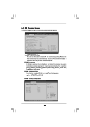
...(tm) tech. Overclock Mode CPU Frequency (MHz) PCIE Frequency (MHz) Strap FSB to MCH [8] [Auto] [Auto] [133] [100] [Auto] Voltage Configuration ASRock VDroop Control [With VDroop] Would you can use this item to Sub Screen F1 General Help F9 Load Defaults F10 Save and Exit ESC Exit... may select [Auto], [400MHz_DDR3 800], [533MHz_DDR3 1066], [667MHz_DDR3 1333] or [800MHz_DDR3 1600]. It should be done at your CPU and motherboard. You may cause damage to load CPU EZ overclocking setting. Load CPU EZ OC Setting You can set up overclocking features. DRAM Timing Configuation...
...(tm) tech. Overclock Mode CPU Frequency (MHz) PCIE Frequency (MHz) Strap FSB to MCH [8] [Auto] [Auto] [133] [100] [Auto] Voltage Configuration ASRock VDroop Control [With VDroop] Would you can use this item to Sub Screen F1 General Help F9 Load Defaults F10 Save and Exit ESC Exit... may select [Auto], [400MHz_DDR3 800], [533MHz_DDR3 1066], [667MHz_DDR3 1333] or [800MHz_DDR3 1600]. It should be done at your CPU and motherboard. You may cause damage to load CPU EZ overclocking setting. Load CPU EZ OC Setting You can set up overclocking features. DRAM Timing Configuation...

