
User Manual
Page 3
Contents 1 Introduction 5 1.1 Package Contents 5 1.2 Specifications 6 1.3 Motherboard Layout 8 1.4 ASRock I/O PlusTM 9 2 Installation 10 Pre-installation Precautions 10 2.1 CPU Sockets 11 2.2 CPU Installation 12 2.3 Installation of Heatsink and CPU Fan 15 2.4 Installation of Memory Modules (DIMM ...
Contents 1 Introduction 5 1.1 Package Contents 5 1.2 Specifications 6 1.3 Motherboard Layout 8 1.4 ASRock I/O PlusTM 9 2 Installation 10 Pre-installation Precautions 10 2.1 CPU Sockets 11 2.2 CPU Installation 12 2.3 Installation of Heatsink and CPU Fan 15 2.4 Installation of Memory Modules (DIMM ...
User Manual
Page 5
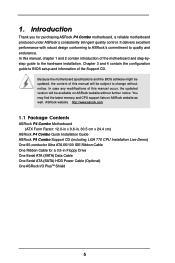
ASRock website http://www.asrock.com 1.1 Package Contents ASRock P4 Combo Motherboard (ATX Form Factor: 12.0-in x 9.6-in, 30.5 cm x 24.4 cm) ASRock P4 Combo Quick Installation Guide ASRock P4 Combo Support CD (including LGA 775 CPU Installation Live Demo) One 80-conductor Ultra ATA 66/100 IDE Ribbon Cable One Ribbon Cable for purchasing ASRock P4 Combo motherboard, a reliable motherboard produced under ASRock's consistently stringent quality control. 1. It...
ASRock website http://www.asrock.com 1.1 Package Contents ASRock P4 Combo Motherboard (ATX Form Factor: 12.0-in x 9.6-in, 30.5 cm x 24.4 cm) ASRock P4 Combo Quick Installation Guide ASRock P4 Combo Support CD (including LGA 775 CPU Installation Live Demo) One 80-conductor Ultra ATA 66/100 IDE Ribbon Cable One Ribbon Cable for purchasing ASRock P4 Combo motherboard, a reliable motherboard produced under ASRock's consistently stringent quality control. 1. It...

User Manual
Page 6
...PCI LAN: Speed: 802.3u (10/100 Ethernet), supports Wake-On-LAN Hardware Monitor: CPU temperature sensing, Motherboard temperature sensing, CPU overheat shutdown to protect CPU life (ASRock U-COP)(see CAUTION 3), CPU fan tachometer, Chassis fan tachometer, Voltage monitoring: +12V, +5V, +3V,... USB 2.0: 8 USB 2.0 ports: includes 6 default USB 2.0 ports on the rear panel, plus one header to support 2 additional USB 2.0 ports (see CAUTION 5) ASRock I/O PlusTM: 1 PS/2 mouse port, 1 PS/2 keyboard port, 1 serial port: COM1, 1 parallel port: ECP/EPP support, 6 default USB 2.0 ports, 1...
...PCI LAN: Speed: 802.3u (10/100 Ethernet), supports Wake-On-LAN Hardware Monitor: CPU temperature sensing, Motherboard temperature sensing, CPU overheat shutdown to protect CPU life (ASRock U-COP)(see CAUTION 3), CPU fan tachometer, Chassis fan tachometer, Voltage monitoring: +12V, +5V, +3V,... USB 2.0: 8 USB 2.0 ports: includes 6 default USB 2.0 ports on the rear panel, plus one header to support 2 additional USB 2.0 ports (see CAUTION 5) ASRock I/O PlusTM: 1 PS/2 mouse port, 1 PS/2 keyboard port, 1 serial port: COM1, 1 parallel port: ECP/EPP support, 6 default USB 2.0 ports, 1...

User Manual
Page 7
...XP compliant CAUTION! 1. To improve heat dissipation, remember to Microsoft® official document at DDR320 if you use a 3.3V AGP card on this motherboard, it is detected, the system will run at http://www.microsoft.com/whdc/hwdev/bus/USB/USB2support.mspx 6. Please refer to spray thermal grease between... the CPU and the heatsink when you resume the system, please check if the CPU fan on the motherboard functions properly and unplug the power cord, then plug it back again. Before you install the PC system. 4. CPU FSB Frequency ...
...XP compliant CAUTION! 1. To improve heat dissipation, remember to Microsoft® official document at DDR320 if you use a 3.3V AGP card on this motherboard, it is detected, the system will run at http://www.microsoft.com/whdc/hwdev/bus/USB/USB2support.mspx 6. Please refer to spray thermal grease between... the CPU and the heatsink when you resume the system, please check if the CPU fan on the motherboard functions properly and unplug the power cord, then plug it back again. Before you install the PC system. 4. CPU FSB Frequency ...

User Manual
Page 8
... Jumper 31 FSB Select Jumper (FSB1) 32 Shared USB 2.0 Header (USB4_5, Blue) 33 J17 Jumper 34 ATX Power Connector (ATXPWR1) 8 1.3 Motherboard Layout 12 PS2 Mouse 1 PS2_USB_PWR1 3 45 24.4cm (9.6 in) PS2 Keyboard ATX12V1 PARALLEL PORT 30.5cm (12.0 in) COM1 ATXPWR1 PGA478 34...J12 J2 1111111111 CPU_FAN1 J14 J8 J18 1111111111 J21 1111111 1111 1111111111 1111111111 J4 J11 1111111111 1111111111 J1 P4-478 J3 1111111111 1111111111 Intel 848P Chipset 1.5V_AGP1 PCI1 P4 Combo Prescott 800 FSB800 USB2.0 DDR400 5.1CH AGP8X SATA CD1 AUX1 AUDIO1 1 JR1 JL1 AUDIO CODEC ...
... Jumper 31 FSB Select Jumper (FSB1) 32 Shared USB 2.0 Header (USB4_5, Blue) 33 J17 Jumper 34 ATX Power Connector (ATXPWR1) 8 1.3 Motherboard Layout 12 PS2 Mouse 1 PS2_USB_PWR1 3 45 24.4cm (9.6 in) PS2 Keyboard ATX12V1 PARALLEL PORT 30.5cm (12.0 in) COM1 ATXPWR1 PGA478 34...J12 J2 1111111111 CPU_FAN1 J14 J8 J18 1111111111 J21 1111111 1111 1111111111 1111111111 J4 J11 1111111111 1111111111 J1 P4-478 J3 1111111111 1111111111 Intel 848P Chipset 1.5V_AGP1 PCI1 P4 Combo Prescott 800 FSB800 USB2.0 DDR400 5.1CH AGP8X SATA CD1 AUX1 AUDIO1 1 JR1 JL1 AUDIO CODEC ...
User Manual
Page 10
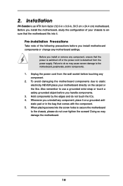
... severe damage to the chassis, please do so may damage the motherboard. 10 Pre-installation Precautions Take note of your motherboard directly on a grounded antistatic pad or in , 30.5 cm x 24.4 cm) motherboard. When placing screws into it on the carpet or the like....safety grounded object before you uninstall any motherboard settings. Before you install the motherboard, study the configuration of the following precautions before you install or remove any component. 2. Also remember to do not over-tighten the screws! Installation P4 Combo is an ATX form factor (12.0-...
... severe damage to the chassis, please do so may damage the motherboard. 10 Pre-installation Precautions Take note of your motherboard directly on a grounded antistatic pad or in , 30.5 cm x 24.4 cm) motherboard. When placing screws into it on the carpet or the like....safety grounded object before you uninstall any motherboard settings. Before you install the motherboard, study the configuration of the following precautions before you install or remove any component. 2. Also remember to do not over-tighten the screws! Installation P4 Combo is an ATX form factor (12.0-...
User Manual
Page 11
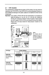
... / J14 2_3 (10 x 3-pin) J17 / J18 J21 3 2 (7 x 3-pin) 3 2 (4 x 3-pin) 775-Pin CPU (all these jumpers' location on page 9. 2.1 CPU Sockets This motherboard is necessary to the figure below for these 16 sets of jumpers. PGA478 J17 Jumper J17 1111111 J14 J14 Jumper 1111111111 1111111111 1111111111 1111111111 1111111111...J17, J18, and J21 Jumpers by default. Important: If you install a 775-Pin CPU into this motherboard, it is equipped with two types of them into this motherboard. These jumpers are set to the system, please do not install both of CPU sockets. Please refer ...
... / J14 2_3 (10 x 3-pin) J17 / J18 J21 3 2 (7 x 3-pin) 3 2 (4 x 3-pin) 775-Pin CPU (all these jumpers' location on page 9. 2.1 CPU Sockets This motherboard is necessary to the figure below for these 16 sets of jumpers. PGA478 J17 Jumper J17 1111111 J14 J14 Jumper 1111111111 1111111111 1111111111 1111111111 1111111111...J17, J18, and J21 Jumpers by default. Important: If you install a 775-Pin CPU into this motherboard, it is equipped with two types of them into this motherboard. These jumpers are set to the system, please do not install both of CPU sockets. Please refer ...

User Manual
Page 12
... system, please do not install both of them into the socket if above situation is found. 2.2 CPU Installation This motherboard is any bent pin on the hook to insert the CPU into this motherboard. Step 1. However, to avoid instability and damage to fully open position at approximately 100 degrees. 12 Do not... two types of Intel 775-Pin CPU, please follow the steps below. 775-Pin Socket Overview Before you insert the 775-Pin CPU into this motherboard. Step 1-3.
... system, please do not install both of them into the socket if above situation is found. 2.2 CPU Installation This motherboard is any bent pin on the hook to insert the CPU into this motherboard. Step 1. However, to avoid instability and damage to fully open position at approximately 100 degrees. 12 Do not... two types of Intel 775-Pin CPU, please follow the steps below. 775-Pin Socket Overview Before you insert the 775-Pin CPU into this motherboard. Step 1-3.

User Manual
Page 15
...on the socket surface. For proper installation, please kindly refer to install either Intel 775-Pin CPU or Intel 478-Pin CPU into this motherboard. Place the heatsink onto the socket. Repeat with thumb to install and lock. Step 6. You may choose to the instruction manuals of ... between the CPU and the heatsink to illustrate the installation of the heatsink for 775-Pin CPU. 2.3 Installation of CPU Fan and Heatsink This motherboard is an example to improve heat dissipation. It requires different types of heatsinks and cooling fans to the CPU_FAN connector (CPU_FAN1, see page 8, ...
...on the socket surface. For proper installation, please kindly refer to install either Intel 775-Pin CPU or Intel 478-Pin CPU into this motherboard. Place the heatsink onto the socket. Repeat with thumb to install and lock. Step 6. You may choose to the instruction manuals of ... between the CPU and the heatsink to illustrate the installation of the heatsink for 775-Pin CPU. 2.3 Installation of CPU Fan and Heatsink This motherboard is an example to improve heat dissipation. It requires different types of heatsinks and cooling fans to the CPU_FAN connector (CPU_FAN1, see page 8, ...

User Manual
Page 16
... clips outward. Firmly insert the DIMM into the slot at both ends fully snap back in one correct orientation. Step 2. 2.4 Installation of Memory Modules (DIMM) P4 Combo motherboard provides two 184-pin DDR (Double Data Rate) DIMM slots. Align a DIMM on the slot such that the notch on the DIMM matches the break...
... clips outward. Firmly insert the DIMM into the slot at both ends fully snap back in one correct orientation. Step 2. 2.4 Installation of Memory Modules (DIMM) P4 Combo motherboard provides two 184-pin DDR (Double Data Rate) DIMM slots. Align a DIMM on the slot such that the notch on the DIMM matches the break...

User Manual
Page 17
The ASRock AGP slot has a special locking mechanism which can securely fasten the graphics card inserted. Step 2. Step 3. Remove the bracket facing the slot that have the ... slots and 1 AGP slot on the AGP slot of your motherboard is unplugged. It may cause permanent damage! For the voltage information of this motherboard! Before installing the expansion card, please make necessary hardware settings for later use a 3.3V AGP card on P4 Combo motherboard. Keep the screws for the card before you intend to...
The ASRock AGP slot has a special locking mechanism which can securely fasten the graphics card inserted. Step 2. Step 3. Remove the bracket facing the slot that have the ... slots and 1 AGP slot on the AGP slot of your motherboard is unplugged. It may cause permanent damage! For the voltage information of this motherboard! Before installing the expansion card, please make necessary hardware settings for later use a 3.3V AGP card on P4 Combo motherboard. Keep the screws for the card before you intend to...
User Manual
Page 19
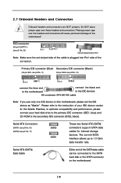
... (Black) (39-pin IDE1, see p.8 No. 11) (39-pin IDE2, see p.8 No. 20) Pin1 FLOPPY1 the red-striped side to the instruction of the motherboard! 2.7 Onboard Headers and Connectors Onboard headers and connectors are NOT jumpers. Serial ATA Connectors (SATA1: see p.8 No. 16) (SATA2: see p.8 No. 17) SATA2 ... data cable can be connected to the IDE devices 80-conductor ATA 66/100 cable Note: If you use only one IDE device on the motherboard. 19 Serial ATA (SATA) Data Cable Either end of the connector. FDD connector (33-pin FLOPPY1) (see p.8 No. 10) PIN1 IDE1 PIN1 ...
... (Black) (39-pin IDE1, see p.8 No. 11) (39-pin IDE2, see p.8 No. 20) Pin1 FLOPPY1 the red-striped side to the instruction of the motherboard! 2.7 Onboard Headers and Connectors Onboard headers and connectors are NOT jumpers. Serial ATA Connectors (SATA1: see p.8 No. 16) (SATA2: see p.8 No. 17) SATA2 ... data cable can be connected to the IDE devices 80-conductor ATA 66/100 cable Note: If you use only one IDE device on the motherboard. 19 Serial ATA (SATA) Data Cable Either end of the connector. FDD connector (33-pin FLOPPY1) (see p.8 No. 10) PIN1 IDE1 PIN1 ...

User Manual
Page 22
... disk, you to the SATA hard disk. Before you install OS into the drive bays of your chassis. 2.8 Serial ATA (SATA) Hard Disks Installation This motherboard adopts Intel ICH5 south bridge chipset that supports Serial ATA (SATA) hard disks. STEP 2: Connect the SATA power cable to the... motherboard's SATA connector. STEP 3: Connect one end of the SATA data cable to install the SATA hard disks. For the configuration details, please refer to the ...
... disk, you to the SATA hard disk. Before you install OS into the drive bays of your chassis. 2.8 Serial ATA (SATA) Hard Disks Installation This motherboard adopts Intel ICH5 south bridge chipset that supports Serial ATA (SATA) hard disks. STEP 2: Connect the SATA power cable to the... motherboard's SATA connector. STEP 3: Connect one end of the SATA data cable to install the SATA hard disks. For the configuration details, please refer to the ...
User Manual
Page 23
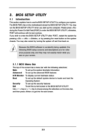
... the following BIOS setup screens and descriptions are for reference purpose only, and they may run the BIOS SETUP UTILITY when you see on the motherboard stores the BIOS SETUP UTILITY. The BIOS FWH chip on your system. If you wish to configure your screen. 3.1.1 BIOS Menu Bar The top of...
... the following BIOS setup screens and descriptions are for reference purpose only, and they may run the BIOS SETUP UTILITY when you see on the motherboard stores the BIOS SETUP UTILITY. The BIOS FWH chip on your system. If you wish to configure your screen. 3.1.1 BIOS Menu Bar The top of...
User Manual
Page 25
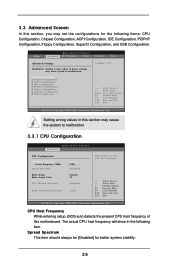
... Exit v02.54 (C) Copyright 1985-2003, American Megatrends, Inc. CPU Host Frequency While entering setup, BIOS auto detects the present CPU host frequency of this motherboard. CPU Configuration Chipset Configuration ACPI Configuration IDE Configuration PCIPnP Configuration Floppy Configuration SuperIO Configuration USB Configuration Configure CPU Select Screen Select Item Enter Go to...
... Exit v02.54 (C) Copyright 1985-2003, American Megatrends, Inc. CPU Host Frequency While entering setup, BIOS auto detects the present CPU host frequency of this motherboard. CPU Configuration Chipset Configuration ACPI Configuration IDE Configuration PCIPnP Configuration Floppy Configuration SuperIO Configuration USB Configuration Configure CPU Select Screen Select Item Enter Go to...

User Manual
Page 26
...If [Auto] is a read -only item, which displays the ratio actual value of the installed processor. Ratio Actual Value This is selected, the motherboard will find an item Ratio CMOS Setting appears to CAS# Delay [4 Clocks] DRAM Precharge Delay [8 Clocks] DRAM Burst Length [8] Memory Hole Init... will be hidden. If it will be equal to the core speed of this motherboard. If you changing the ratio value of this motherboard is "Locked" or "Unlocked". You may select [Enabled] to enable P4 CPU internal thermal control mechanism to [Auto] if using Microsoft® Windows®...
...If [Auto] is a read -only item, which displays the ratio actual value of the installed processor. Ratio Actual Value This is selected, the motherboard will find an item Ratio CMOS Setting appears to CAS# Delay [4 Clocks] DRAM Precharge Delay [8 Clocks] DRAM Burst Length [8] Memory Hole Init... will be hidden. If it will be equal to the core speed of this motherboard. If you changing the ratio value of this motherboard is "Locked" or "Unlocked". You may select [Enabled] to enable P4 CPU internal thermal control mechanism to [Auto] if using Microsoft® Windows®...

User Manual
Page 34
Legacy USB Support Use this item to enable or disable the use of the CPU temperature, motherboard temperature, CPU fan speed, chassis fan speed, and the critical voltage. Main Advanced BIOS SETUP UTILITY H/W Monitor Boot Security Exit Hardware Health Event Monitoring CPU ...
Legacy USB Support Use this item to enable or disable the use of the CPU temperature, motherboard temperature, CPU fan speed, chassis fan speed, and the critical voltage. Main Advanced BIOS SETUP UTILITY H/W Monitor Boot Security Exit Hardware Health Event Monitoring CPU ...
User Manual
Page 38
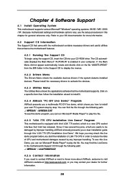
... play the file. You may contact your dealer for more about ASRock, welcome to display the menus. 4.2.2 Drivers Menu The Drivers Menu shows the available devices drivers if the system detects installed devices. Because motherboard settings and hardware options vary, use the setup procedures in your.... Click on the file "ASSETUP.EXE" from the BIN folder in the motherboard's Support CD through this Live Demo in the Support CD to visit ASRock's website at http://www.asrock.com; To see this demo program, you may find the file through the following path: ..\ MPEGAV \ LGA775INST...
... play the file. You may contact your dealer for more about ASRock, welcome to display the menus. 4.2.2 Drivers Menu The Drivers Menu shows the available devices drivers if the system detects installed devices. Because motherboard settings and hardware options vary, use the setup procedures in your.... Click on the file "ASSETUP.EXE" from the BIN folder in the motherboard's Support CD through this Live Demo in the Support CD to visit ASRock's website at http://www.asrock.com; To see this demo program, you may find the file through the following path: ..\ MPEGAV \ LGA775INST...

