
User Manual
Page 4
... 36 3.1 Introduction 36 3.1.1 BIOS Menu Bar 36 3.1.2 Navigation Keys 37 3.2 Main Screen 37 3.3 Smart Screen 38 3.4 Advanced Screen 39 3.4.1 CPU Configuration 39 3.4.2 Chipset Configuration 44 3.4.3 ACPI Configuration 46 3.4.4 IDE ...
... 36 3.1 Introduction 36 3.1.1 BIOS Menu Bar 36 3.1.2 Navigation Keys 37 3.2 Main Screen 37 3.3 Smart Screen 38 3.4 Advanced Screen 39 3.4.1 CPU Configuration 39 3.4.2 Chipset Configuration 44 3.4.3 ACPI Configuration 46 3.4.4 IDE ...
User Manual
Page 5
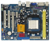
... the BIOS software might be available on ASRock website as well. www.asrock.com/support/index.asp 1.1 Package Contents One ASRock N68PV-GS Motherboard (Micro ATX Form Factor: 9.6-in x 7.2-in, 24.4 cm x 18.3 cm) One ASRock N68PV-GS Quick Installation Guide Two ASRock N68PV-GS Support ...It delivers excellent performance with robust design conforming to ASRock's commitment to BIOS setup and information of this motherboard, please visit our website for purchasing ASRock N68PV-GS motherboard, a reliable motherboard produced under ASRock's consistently stringent quality control. You may find the...
... the BIOS software might be available on ASRock website as well. www.asrock.com/support/index.asp 1.1 Package Contents One ASRock N68PV-GS Motherboard (Micro ATX Form Factor: 9.6-in x 7.2-in, 24.4 cm x 18.3 cm) One ASRock N68PV-GS Quick Installation Guide Two ASRock N68PV-GS Support ...It delivers excellent performance with robust design conforming to ASRock's commitment to BIOS setup and information of this motherboard, please visit our website for purchasing ASRock N68PV-GS motherboard, a reliable motherboard produced under ASRock's consistently stringent quality control. You may find the...
User Manual
Page 7
...BIOS Feature - 4Mb AMI BIOS - Boot Failure Guard (B.F.G.) - Chassis Fan Tachometer - HD Audio Jack: Line in header - Intelligent Energy Saver (see CAUTION 9) - 1 x ATA133 IDE connector (supports 2 x IDE devices) - 1 x Floppy connector - 1 x COM port header - 1 x Print port header - Hybrid Booster: - ASRock AM2 Boost: ASRock... 12V power connector - CPU Quiet Fan - ACPI 1.1 Compliance Wake Up Events - CPU Fan Tachometer - ASRock OC Tuner (see CAUTION 15) Hardware - Drivers, Utilities, AntiVirus Software (Trial Version) Unique Feature - CPU...
...BIOS Feature - 4Mb AMI BIOS - Boot Failure Guard (B.F.G.) - Chassis Fan Tachometer - HD Audio Jack: Line in header - Intelligent Energy Saver (see CAUTION 9) - 1 x ATA133 IDE connector (supports 2 x IDE devices) - 1 x Floppy connector - 1 x COM port header - 1 x Print port header - Hybrid Booster: - ASRock AM2 Boost: ASRock... 12V power connector - CPU Quiet Fan - ACPI 1.1 Compliance Wake Up Events - CPU Fan Tachometer - ASRock OC Tuner (see CAUTION 15) Hardware - Drivers, Utilities, AntiVirus Software (Trial Version) Unique Feature - CPU...
User Manual
Page 8
...components and devices of memory modules on this motherboard requires the proper hardware configuration. ASRock website http://www.asrock.com 5. The maximum shared memory size is defined by overclocking. ASRock website http://www.asrock.com 2. Whether 1066MHz memory speed is subject to change. Please refer to ...4GB for the reservation for the minimum hardware requirement and the passed 1080p Blu-ray (BD) / HD-DVD films in the BIOS, applying Untied Overclocking Technology, or using the thirdparty overclocking tools. Overclocking may use the DVI to HDMI adapter to convert this...
...components and devices of memory modules on this motherboard requires the proper hardware configuration. ASRock website http://www.asrock.com 5. The maximum shared memory size is defined by overclocking. ASRock website http://www.asrock.com 2. Whether 1066MHz memory speed is subject to change. Please refer to ...4GB for the reservation for the minimum hardware requirement and the passed 1080p Blu-ray (BD) / HD-DVD films in the BIOS, applying Untied Overclocking Technology, or using the thirdparty overclocking tools. Overclocking may use the DVI to HDMI adapter to convert this...

User Manual
Page 9
... in the BIOS setup, the memory performance will improve up to disable this function will automatically shutdown. Please visit our website for all CPU/DRAM configurations. ASRock website: http://www.asrock.com 13. You may cause the instability of output phases to spray thermal grease ...you enable this function in advance. The voltage regulator can not guarantee the system stability for the operation procedures of ASRock OC Tuner. This motherboard supports ASRock AM2 Boost overclocking technology. However, we can reduce the number of the system or damage the CPU. 14....
... in the BIOS setup, the memory performance will improve up to disable this function will automatically shutdown. Please visit our website for all CPU/DRAM configurations. ASRock website: http://www.asrock.com 13. You may cause the instability of output phases to spray thermal grease ...you enable this function in advance. The voltage regulator can not guarantee the system stability for the operation procedures of ASRock OC Tuner. This motherboard supports ASRock AM2 Boost overclocking technology. However, we can reduce the number of the system or damage the CPU. 14....

User Manual
Page 12
...: FRONT Bottom: MIC IN LAN PHY SATAII_1 (PORT 0) SATAII_2 (PORT 1) SATAII_3 (PORT 2) SATAII_4 (PORT 3) PCIE1 NVIDIA GeForce 7050 / nForce 630A MCP IDE1 PCIE2 N68PV-GS PCI1 RoHS RAID 4Mb BIOS CMOS BATTERY AUDIO CODEC CD1 1 HD_AUDIO1 FLOPPY1 20 19 PCI2 1 COM1 PANEL 1 PLED PWRBTN 1 HDLED RESET 1 USB4_5 1 USB6_7 CHA_FAN1 CLRCMOS1 1 SPEAKER1 1 18 17...
...: FRONT Bottom: MIC IN LAN PHY SATAII_1 (PORT 0) SATAII_2 (PORT 1) SATAII_3 (PORT 2) SATAII_4 (PORT 3) PCIE1 NVIDIA GeForce 7050 / nForce 630A MCP IDE1 PCIE2 N68PV-GS PCI1 RoHS RAID 4Mb BIOS CMOS BATTERY AUDIO CODEC CD1 1 HD_AUDIO1 FLOPPY1 20 19 PCI2 1 COM1 PANEL 1 PLED PWRBTN 1 HDLED RESET 1 USB4_5 1 USB6_7 CHA_FAN1 CLRCMOS1 1 SPEAKER1 1 18 17...
User Manual
Page 19
... PCI Express VGA card, you wish to page 17 for proper expansion card installation procedures for the second monitor. When you do not adjust the BIOS setup, the default value of the multi-monitor according to this motherboard. D. E. Set the "Screen Resolution" and "Color Quality" as Secondary. Please refer to be...
... PCI Express VGA card, you wish to page 17 for proper expansion card installation procedures for the second monitor. When you do not adjust the BIOS setup, the default value of the multi-monitor according to this motherboard. D. E. Set the "Screen Resolution" and "Color Quality" as Secondary. Please refer to be...
User Manual
Page 21
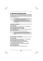
...signal. For Windows® XP / XP 64-bit OS Step 1: Set up BIOS. B. Step 2: Install HDMI audio driver to "Digital Output Device (HDMI)". Install "Onboard HDMI HD Audio Driver" from ASRock Support CD to [Auto]. Therefore, the onboard audio jack will output the audio ...signal through HDMI audio. Enter BIOS SETUP UTILITY Advanced screen Chipset Configuration. A. Click "Start" button, select "Settings", and ...
...signal. For Windows® XP / XP 64-bit OS Step 1: Set up BIOS. B. Step 2: Install HDMI audio driver to "Digital Output Device (HDMI)". Install "Onboard HDMI HD Audio Driver" from ASRock Support CD to [Auto]. Therefore, the onboard audio jack will output the audio ...signal through HDMI audio. Enter BIOS SETUP UTILITY Advanced screen Chipset Configuration. A. Click "Start" button, select "Settings", and ...

User Manual
Page 22
Jumper Setting PS2_USB_PW1 1_2 2_3 Short pin2, pin3 to enable (see p.12, No. 14) 1_2 2_3 Default Clear CMOS Note: CLRCMOS1 allows you update the BIOS. Clear CMOS Jumper (CLRCMOS1) (see p.12, No. 1) +5V +5VSB +5VSB (standby) for PS/2 or USB wake up the system first, and then shut it requires 2 ...: To select +5VSB, it down before you do not clear the CMOS right after you to clear the CMOS when you just finish updating the BIOS, you must boot up events. The illustration shows a 3-pin jumper whose pin1 and pin2 are setup. The data in CMOS. However, please do the ...
Jumper Setting PS2_USB_PW1 1_2 2_3 Short pin2, pin3 to enable (see p.12, No. 14) 1_2 2_3 Default Clear CMOS Note: CLRCMOS1 allows you update the BIOS. Clear CMOS Jumper (CLRCMOS1) (see p.12, No. 1) +5V +5VSB +5VSB (standby) for PS/2 or USB wake up the system first, and then shut it requires 2 ...: To select +5VSB, it down before you do not clear the CMOS right after you to clear the CMOS when you just finish updating the BIOS, you must boot up events. The illustration shows a 3-pin jumper whose pin1 and pin2 are setup. The data in CMOS. However, please do the ...

User Manual
Page 25
Enter BIOS Setup Utility. Enter Windows system. Click the icon on the lower right hand taskbar to [Enabled]. For Windows® 2000 / XP / XP 64-bit OS: ...
Enter BIOS Setup Utility. Enter Windows system. Click the icon on the lower right hand taskbar to [Enabled]. For Windows® 2000 / XP / XP 64-bit OS: ...
User Manual
Page 31
...want to install Windows® 2000 / Windows® XP / Windows® XP 64-bit on your system. (There are two ASRock Support CD in your disk, please visit the below procedures according to boot your SATA / SATAII HDDs without RAID functions, please follow ...Set the "SATA Operation Mode" option to include SP4. A. Please follow below website for boot devices selection appears. B. Please select CD- A. Enter BIOS SETUP UTILITY Advanced screen IDE Configuration. STEP 2: Make a SATA / SATAII driver diskette. C. Using SATA / SATAII HDDs with NCQ and Hot Plug functions...
...want to install Windows® 2000 / Windows® XP / Windows® XP 64-bit on your system. (There are two ASRock Support CD in your disk, please visit the below procedures according to boot your SATA / SATAII HDDs without RAID functions, please follow ...Set the "SATA Operation Mode" option to include SP4. A. Please follow below website for boot devices selection appears. B. Please select CD- A. Enter BIOS SETUP UTILITY Advanced screen IDE Configuration. STEP 2: Make a SATA / SATAII driver diskette. C. Using SATA / SATAII HDDs with NCQ and Hot Plug functions...

User Manual
Page 32
...: 1. STEP 2: Install Windows® 2000 / XP / XP 64-bit OS on your SATA / SATAII HDDs without NCQ and Hot Plug functions STEP 1: Set Up BIOS. Generate RAID Driver diskette for WindowsXP64 4. The system will start to continue Please insert a floppy diskette into the floppy diskette. At the beginning of Windows...Press any key. E. Using SATA / SATAII HDDs with NCQ and Hot Plug functions 32 D. The drivers are as below steps. Then you install. Enter BIOS SETUP UTILITY Advanced screen IDE Configuration. Generate RAID Driver diskette for Windows2000/XP 2.
...: 1. STEP 2: Install Windows® 2000 / XP / XP 64-bit OS on your SATA / SATAII HDDs without NCQ and Hot Plug functions STEP 1: Set Up BIOS. Generate RAID Driver diskette for WindowsXP64 4. The system will start to continue Please insert a floppy diskette into the floppy diskette. At the beginning of Windows...Press any key. E. Using SATA / SATAII HDDs with NCQ and Hot Plug functions 32 D. The drivers are as below steps. Then you install. Enter BIOS SETUP UTILITY Advanced screen IDE Configuration. Generate RAID Driver diskette for Windows2000/XP 2.

User Manual
Page 33
... proper procedures of making a SP4 disk: http://www.microsoft.com/Windows2000/downloads/servicepacks/sp4/spdeploy. A. Enter BIOS SETUP UTILITY Advanced screen IDE Configuration. page, please insert the ASRock Support CD into the optical drive again to install Windows?" Set the "SATA Operation Mode" option to load...[AHCI]. htm#the_integrated_installation_fmay 33 NVIDIA® AHCI drivers are in the following path in our Support CD: (There are two ASRock Support CD in your system. STEP 1: Set Up BIOS. A. When you see "Where do you want to continue the installation.
... proper procedures of making a SP4 disk: http://www.microsoft.com/Windows2000/downloads/servicepacks/sp4/spdeploy. A. Enter BIOS SETUP UTILITY Advanced screen IDE Configuration. page, please insert the ASRock Support CD into the optical drive again to install Windows?" Set the "SATA Operation Mode" option to load...[AHCI]. htm#the_integrated_installation_fmay 33 NVIDIA® AHCI drivers are in the following path in our Support CD: (There are two ASRock Support CD in your system. STEP 1: Set Up BIOS. A. When you see "Where do you want to continue the installation.

User Manual
Page 34
...Windows® setup, press F6 to our website in the Support CD: .. \ RAID Installation Guide NOTE. NVIDIA RAID Driver (required) B. Enter BIOS SETUP UTILITY Advanced screen IDE Configuration. NVIDIA nForce Storage Controller (required) Please select A and B for RAID mode, you want to manage (create..., or rebuild) RAID functions on SATA / SATAII HDDs, you need to set up "SATA Operation Mode" to [RAID] in BIOS first. ASRock website http://www.asrock.com 34 A. B. Select the drivers to [RAID]. Please specify the first RAID driver and then specify again for Windows® ...
...Windows® setup, press F6 to our website in the Support CD: .. \ RAID Installation Guide NOTE. NVIDIA RAID Driver (required) B. Enter BIOS SETUP UTILITY Advanced screen IDE Configuration. NVIDIA nForce Storage Controller (required) Please select A and B for RAID mode, you want to manage (create..., or rebuild) RAID functions on SATA / SATAII HDDs, you need to set up "SATA Operation Mode" to [RAID] in BIOS first. ASRock website http://www.asrock.com 34 A. B. Select the drivers to [RAID]. Please specify the first RAID driver and then specify again for Windows® ...
User Manual
Page 35
...; VistaTM / Windows® VistaTM 64-bit optical disk into the optical drive to boot your system, and follow below steps. Enter BIOS SETUP UTILITY Advanced screen IDE Configuration. Insert the Windows® VistaTM / Windows® VistaTM 64-bit optical disk into the optical drive... again to continue the installation. NVIDIA® RAID drivers are two ASRock Support CD in the Support CD: .. \ RAID Installation Guide 2.16 Untied Overclocking Technology This motherboard supports Untied Overclocking Technology, which means...
...; VistaTM / Windows® VistaTM 64-bit optical disk into the optical drive to boot your system, and follow below steps. Enter BIOS SETUP UTILITY Advanced screen IDE Configuration. Insert the Windows® VistaTM / Windows® VistaTM 64-bit optical disk into the optical drive... again to continue the installation. NVIDIA® RAID drivers are two ASRock Support CD in the Support CD: .. \ RAID Installation Guide 2.16 Untied Overclocking Technology This motherboard supports Untied Overclocking Technology, which means...

User Manual
Page 36
... the reset button on the menu bar, and then press to choose among the selections on the system chassis. If you wish to enter the BIOS SETUP UTILITY after POST, restart the system by pressing + + , or by turning the system off and then back on the motherboard stores the... is constantly being updated, the following selections: Main To set up the system time/date information Advanced To set up the advanced BIOS features H/W Monitor To display current hardware status Boot To set up the default system device to locate and load the Operating System Security To set ...
... the reset button on the menu bar, and then press to choose among the selections on the system chassis. If you wish to enter the BIOS SETUP UTILITY after POST, restart the system by pressing + + , or by turning the system off and then back on the motherboard stores the... is constantly being updated, the following selections: Main To set up the system time/date information Advanced To set up the advanced BIOS features H/W Monitor To display current hardware status Boot To set up the default system device to locate and load the Operating System Security To set ...

User Manual
Page 37
... UTILITY Main Smart Advanced H/W Monitor Boot Security Exit System Overview System Time System Date [14:00:09] [Tue 09/02/2008] BIOS Version : N68PV-GS P1.00 Processor Type : AMD Athlon(tm) Dual Core Processor 4450e (64bit) Processor Speed : 2300MHz Microcode Update : 60FB2/0 L1 Cache Size : 256KB L2...Year] Use this item to select a field. 3.1.2 Navigation Keys Please check the following table for all the settings To save changes and exit the BIOS SETUP UTILITY To jump to specify the system date. 37 Use [+] or [-] to configure system Time. +Tab F1 F9 F10 ESC Select Screen...
... UTILITY Main Smart Advanced H/W Monitor Boot Security Exit System Overview System Time System Date [14:00:09] [Tue 09/02/2008] BIOS Version : N68PV-GS P1.00 Processor Type : AMD Athlon(tm) Dual Core Processor 4450e (64bit) Processor Speed : 2300MHz Microcode Update : 60FB2/0 L1 Cache Size : 256KB L2...Year] Use this item to select a field. 3.1.2 Navigation Keys Please check the following table for all the settings To save changes and exit the BIOS SETUP UTILITY To jump to specify the system date. 37 Use [+] or [-] to configure system Time. +Tab F1 F9 F10 ESC Select Screen...

User Manual
Page 38
... Mode This performance setup AHCI mode may not be compatible with all the setup questions. Save Changes and Exit When you can load the BIOS setup according to Sub Screen F1 General Help F9 Load Defaults F10 Save and Exit ESC Exit v02.54 (C) Copyright 1985-2005, American ...Megatrends, Inc. Load BIOS Defaults Load BIOS default values for this operation. Load Performance Setup Default (IDE/SATA) This performance setup default may not be used for this option, it...
... Mode This performance setup AHCI mode may not be compatible with all the setup questions. Save Changes and Exit When you can load the BIOS setup according to Sub Screen F1 General Help F9 Load Defaults F10 Save and Exit ESC Exit v02.54 (C) Copyright 1985-2005, American ...Megatrends, Inc. Load BIOS Defaults Load BIOS default values for this operation. Load Performance Setup Default (IDE/SATA) This performance setup default may not be used for this option, it...
User Manual
Page 39
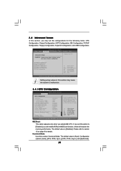
..., PCIPnP Configuration, Floppy Configuration, SuperIO Configuration, and USB Configuration. BIOS SETUP UTILITY Main Smart Advanced H/W Monitor Boot Security Exit Advanced Settings Options for details. If you will enable ASRock AM2 Boost function, which will be left at the rated frequency/...[CPU, PCIE, Async.] and [Optimized]. 39 If Manual, multiplier and voltage will be set this to malfunction. 3.4.1CPU Configuration BIOS SETUP UTILITY Advanced CPU Configuration AM2 Boost Overclock Mode CPU Frequency (MHz) PCIE Frequency (MHz) CPU/LDT Spread Spectrum PCIE Spread Spectrum...
..., PCIPnP Configuration, Floppy Configuration, SuperIO Configuration, and USB Configuration. BIOS SETUP UTILITY Main Smart Advanced H/W Monitor Boot Security Exit Advanced Settings Options for details. If you will enable ASRock AM2 Boost function, which will be left at the rated frequency/...[CPU, PCIE, Async.] and [Optimized]. 39 If Manual, multiplier and voltage will be set this to malfunction. 3.4.1CPU Configuration BIOS SETUP UTILITY Advanced CPU Configuration AM2 Boost Overclock Mode CPU Frequency (MHz) PCIE Frequency (MHz) CPU/LDT Spread Spectrum PCIE Spread Spectrum...

User Manual
Page 41
.... otherwise, it will be hidden. However, for safety and system stability, it is not recommended to adjust the value of Processor Frequency and Processor Voltage. BIOS SETUP UTILITY Advanced CPU Configuration AM2 Boost Overclock Mode CPU Frequency (MHz) PCIE Frequency (MHz) CPU/LDT Spread Spectrum PCIE Spread Spectrum SATA Spread Spectrum...
.... otherwise, it will be hidden. However, for safety and system stability, it is not recommended to adjust the value of Processor Frequency and Processor Voltage. BIOS SETUP UTILITY Advanced CPU Configuration AM2 Boost Overclock Mode CPU Frequency (MHz) PCIE Frequency (MHz) CPU/LDT Spread Spectrum PCIE Spread Spectrum SATA Spread Spectrum...


