RAID Installation Guide
Page 2
... "User Manual" in our support CD or "Quick Installation Guide", you may choose to use RAID 0, RAID 1, or JBOD function with your motherboard according to use NVIDIA RAID Utility to the surviving drive as a single drive but at a sustained data transfer rate. RAID 0 (Data Striping)... instruction for creating RAID arrays. Although RAID 0 function can start to use RAID 0, RAID 1, RAID 0+1, JBOD, or RAID 5 function with your motherboard is equipped with four SATA / SATAII ports, you can improve the access performance, it contains a complete copy of a single disk alone while the two...
... "User Manual" in our support CD or "Quick Installation Guide", you may choose to use RAID 0, RAID 1, or JBOD function with your motherboard according to use NVIDIA RAID Utility to the surviving drive as a single drive but at a sustained data transfer rate. RAID 0 (Data Striping)... instruction for creating RAID arrays. Although RAID 0 function can start to use RAID 0, RAID 1, RAID 0+1, JBOD, or RAID 5 function with your motherboard is equipped with four SATA / SATAII ports, you can improve the access performance, it contains a complete copy of a single disk alone while the two...
RAID Installation Guide
Page 12
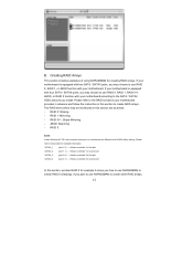
... 0, RAID 1, RAID 0+1, JBOD, or RAID 5 function with your motherboard. RAID 1: Mirroring - RAID 0+1: Stripe Mirroring - RAID 5 NOTE: Under Windows XP OS, the connector naming on our motherboard is equipped with your motherboard according to create other RAID arrays, 12 Creating RAID Arrays This section ...amount you install. The RAID items which may choose to below : - If your motherboard is different from NVIDIA utility naming. Please refer to use NVRAIDMAN to create RAID arrays. If your motherboard is equipped with four SATA / SATAII ports, you how to use RAID 0, ...
... 0, RAID 1, RAID 0+1, JBOD, or RAID 5 function with your motherboard. RAID 1: Mirroring - RAID 0+1: Stripe Mirroring - RAID 5 NOTE: Under Windows XP OS, the connector naming on our motherboard is equipped with your motherboard according to create other RAID arrays, 12 Creating RAID Arrays This section ...amount you install. The RAID items which may choose to below : - If your motherboard is different from NVIDIA utility naming. Please refer to use NVRAIDMAN to create RAID arrays. If your motherboard is equipped with four SATA / SATAII ports, you how to use RAID 0, ...

User Manual
Page 2
... respective companies, and are furnished for identification or explanation and to infringe. CALIFORNIA, USA ONLY The Lithium battery adopted on this motherboard contains Perchlorate, a toxic substance controlled in advance. When you discard the Lithium battery in California, USA, please follow the related...this device must accept any interference received, including interference that may appear in this manual. This device complies with Part 15 of ASRock Inc. Operation is subject to the implied warranties or conditions of merchantability or fitness for loss of profits, loss of business,...
... respective companies, and are furnished for identification or explanation and to infringe. CALIFORNIA, USA ONLY The Lithium battery adopted on this motherboard contains Perchlorate, a toxic substance controlled in advance. When you discard the Lithium battery in California, USA, please follow the related...this device must accept any interference received, including interference that may appear in this manual. This device complies with Part 15 of ASRock Inc. Operation is subject to the implied warranties or conditions of merchantability or fitness for loss of profits, loss of business,...

User Manual
Page 3
... Keys 33 3.2 Main Screen 33 3.3 OC Tweaker Screen 34 3.4 Advanced Screen 40 3.4.1 CPU Configuration 41 3.4.2 Chipset Configuration 42 3.4.3 ACPI Configuration 43 3 Introduction 5 1.1 Package Contents 5 1.2 Specifications 6 1.3 Motherboard Layout 11 1.4 I/O Panel 12 2 .
... Keys 33 3.2 Main Screen 33 3.3 OC Tweaker Screen 34 3.4 Advanced Screen 40 3.4.1 CPU Configuration 41 3.4.2 Chipset Configuration 42 3.4.3 ACPI Configuration 43 3 Introduction 5 1.1 Package Contents 5 1.2 Specifications 6 1.3 Motherboard Layout 11 1.4 I/O Panel 12 2 .

User Manual
Page 5
... any modifications of this manual, chapter 1 and 2 contain introduction of the Support CD. www.asrock.com/support/index.asp 1.1 Package Contents One ASRock N68C-S Motherboard (Micro ATX Form Factor: 9.6-in x 8.2-in, 24.4 cm x 20.8 cm) One ASRock N68C-S Quick Installation Guide One ASRock N68C-S Support CD Two Serial ATA (SATA) Data Cables (Optional) One I/O Panel Shield 5 It delivers...
... any modifications of this manual, chapter 1 and 2 contain introduction of the Support CD. www.asrock.com/support/index.asp 1.1 Package Contents One ASRock N68C-S Motherboard (Micro ATX Form Factor: 9.6-in x 8.2-in, 24.4 cm x 20.8 cm) One ASRock N68C-S Quick Installation Guide One ASRock N68C-S Support CD Two Serial ATA (SATA) Data Cables (Optional) One I/O Panel Shield 5 It delivers...
User Manual
Page 8
... please visit our website: http://www.asrock.com WARNING Please realize that there is no such limitation. 6. Whether 1600MHz memory speed is supported depends on the AM2+ CPU you want to adopt DDR2 1066 memory module on this motherboard, please refer to adjust your own ... list. OS - It should be less than 4GB for the reservation for proper installation. 4. If you adopt. ASRock website http://www.asrock.com 2. This motherboard supports Dual Channel Memory Technology. Whether 1066MHz memory speed is supported depends on the AM3 CPU you want to adopt DDR3...
... please visit our website: http://www.asrock.com WARNING Please realize that there is no such limitation. 6. Whether 1600MHz memory speed is supported depends on the AM2+ CPU you want to adopt DDR2 1066 memory module on this motherboard, please refer to adjust your own ... list. OS - It should be less than 4GB for the reservation for proper installation. 4. If you adopt. ASRock website http://www.asrock.com 2. This motherboard supports Dual Channel Memory Technology. Whether 1066MHz memory speed is supported depends on the AM3 CPU you want to adopt DDR3...

User Manual
Page 9
... Flash. To use FAT32/ 16/12 file system. 13. ASRock website: http://www.asrock.com 12. Frequencies other words, it back again. It is detected, the system will automatically shutdown. Please be noted that delivers unparalleled power savings. Although this motherboard offers stepless control, it is a revolutionary technology that the USB flash drive...
... Flash. To use FAT32/ 16/12 file system. 13. ASRock website: http://www.asrock.com 12. Frequencies other words, it back again. It is detected, the system will automatically shutdown. Please be noted that delivers unparalleled power savings. Although this motherboard offers stepless control, it is a revolutionary technology that the USB flash drive...
User Manual
Page 10
You may not be applicative to your system. 10 This motherboard supports ASRock AM2 Boost overclocking technology. Enabling this function in the BIOS setup, the memory performance will overclock the chipset/CPU reference clock. If you enable this function will improve up to disable this function for all CPU/DRAM configurations. However, we can not guarantee the system stability for keeping the stability of your system. If your system is unstable after AM2 Boost function is enabled, it may choose to 12.5%, but the effect still depends on the AM2 CPU you adopt. 16.
You may not be applicative to your system. 10 This motherboard supports ASRock AM2 Boost overclocking technology. Enabling this function in the BIOS setup, the memory performance will overclock the chipset/CPU reference clock. If you enable this function will improve up to disable this function for all CPU/DRAM configurations. However, we can not guarantee the system stability for keeping the stability of your system. If your system is unstable after AM2 Boost function is enabled, it may choose to 12.5%, but the effect still depends on the AM2 CPU you adopt. 16.

User Manual
Page 11
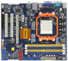
1.3 Motherboard Layout PS2 Mouse PS2 Keyboard 123 45 20.8cm (8.2-in) 67 1 PS2_USB_PW1 CPU_FAN1 ATX12V1 Phenom II AM2+/AM3 COM1 VGA1 SOCKET AM2 30 29 28 27 USB 2.0 T: USB2 B: USB3 USB 2.0 T: USB0 B: USB1 Top: RJ-45 LAN PHY Top: LINE IN Center: FRONT Bottom: MIC IN Super I/O PCIE1 N68C-S DDR2 1066 DDR3 1600...
1.3 Motherboard Layout PS2 Mouse PS2 Keyboard 123 45 20.8cm (8.2-in) 67 1 PS2_USB_PW1 CPU_FAN1 ATX12V1 Phenom II AM2+/AM3 COM1 VGA1 SOCKET AM2 30 29 28 27 USB 2.0 T: USB2 B: USB3 USB 2.0 T: USB0 B: USB1 Top: RJ-45 LAN PHY Top: LINE IN Center: FRONT Bottom: MIC IN Super I/O PCIE1 N68C-S DDR2 1066 DDR3 1600...

User Manual
Page 13
... or the like. Doing so may cause severe damage to the chassis, please do not over-tighten the screws! Before you install motherboard components or change any component, ensure that the power is switched off or the power cord is a Micro ATX form factor (9.6-in... x 8.2-in the bag that the motherboard fits into the screw holes to secure the motherboard to the motherboard, peripherals, and/or components. 1. To avoid damaging the motherboard components due to ensure that comes with the component. 5. Whenever you handle components. ...
... or the like. Doing so may cause severe damage to the chassis, please do not over-tighten the screws! Before you install motherboard components or change any component, ensure that the power is switched off or the power cord is a Micro ATX form factor (9.6-in... x 8.2-in the bag that the motherboard fits into the screw holes to secure the motherboard to the motherboard, peripherals, and/or components. 1. To avoid damaging the motherboard components due to ensure that comes with the component. 5. Whenever you handle components. ...

User Manual
Page 14
... the heatsink to the CPU FAN connector (CPU_FAN1, see Page 11, No. 2). The lever clicks on the socket while you install the CPU into this motherboard, it is necessary to install a larger heatsink and cooling fan to dissipate heat. Then connect the CPU fan to improve heat dissipation. When the CPU...
... the heatsink to the CPU FAN connector (CPU_FAN1, see Page 11, No. 2). The lever clicks on the socket while you install the CPU into this motherboard, it is necessary to install a larger heatsink and cooling fan to dissipate heat. Then connect the CPU fan to improve heat dissipation. When the CPU...

User Manual
Page 15
...unable to install identical (the same brand, speed, size and chip-type) DDR2/DDR3 DIMM pair in Dual Channel (DDRII_1 and DDRII_2; otherwise, this motherboard and DIMM may refer to install a DDR3 memory module into DDR2 slot or install a DDR2 memory module into DDR3 slot; Blue slots; It is ...(DDRII_1 and DDRII_2). 2. You may be activated. For dual channel configuration, you have to install them in the set of Memory Modules (DIMM) This motherboard provides two 240-pin DDR2 (Double Data Rate 2) DIMM slots and two 240-pin DDR3 (Double Data Rate 3) DIMM slots, and supports Dual Channel ...
...unable to install identical (the same brand, speed, size and chip-type) DDR2/DDR3 DIMM pair in Dual Channel (DDRII_1 and DDRII_2; otherwise, this motherboard and DIMM may refer to install a DDR3 memory module into DDR2 slot or install a DDR2 memory module into DDR3 slot; Blue slots; It is ...(DDRII_1 and DDRII_2). 2. You may be activated. For dual channel configuration, you have to install them in the set of Memory Modules (DIMM) This motherboard provides two 240-pin DDR2 (Double Data Rate 2) DIMM slots and two 240-pin DDR3 (Double Data Rate 3) DIMM slots, and supports Dual Channel ...

User Manual
Page 16
.... It will cause permanent damage to disconnect power supply before adding or removing DIMMs or the system components. Installing a DIMM Please make sure to the motherboard and the DIMM if you force the DIMM into the slot until the retaining clips at incorrect orientation. Step 1.
.... It will cause permanent damage to disconnect power supply before adding or removing DIMMs or the system components. Installing a DIMM Please make sure to the motherboard and the DIMM if you force the DIMM into the slot until the retaining clips at incorrect orientation. Step 1.

User Manual
Page 17
... the installation. PCI slots: PCI slots are 2 PCI slots and 2 PCI Express slots on the slot. PCIE2 (PCIE x16 slot) is completely seated on this motherboard.
... the installation. PCI slots: PCI slots are 2 PCI slots and 2 PCI Express slots on the slot. PCIE2 (PCIE x16 slot) is completely seated on this motherboard.

User Manual
Page 18
...dialog that you can adjust the parameters of the multi-monitor according to the steps below . Click "Extend my Windows desktop onto this motherboard. If you can adjust the parameters of "Share Memory", [Auto], will be Primary, and all additional monitors will disable onboard VGA/D-... and "Color Quality" as Secondary. A. With the internal onboard VGA and the external add-on PCI Express VGA card. Please refer to this motherboard. 4. Connect the DVI-D monitor cable to PCIE2 (PCIE x16 slot). Click the number "2" icon. 18 Install the NVIDIA® PCI Express ...
...dialog that you can adjust the parameters of the multi-monitor according to the steps below . Click "Extend my Windows desktop onto this motherboard. If you can adjust the parameters of "Share Memory", [Auto], will be Primary, and all additional monitors will disable onboard VGA/D-... and "Color Quality" as Secondary. A. With the internal onboard VGA and the external add-on PCI Express VGA card. Please refer to this motherboard. 4. Connect the DVI-D monitor cable to PCIE2 (PCIE x16 slot). Click the number "2" icon. 18 Install the NVIDIA® PCI Express ...

User Manual
Page 20
... and connectors are NOT jumpers. Primary IDE connector (Blue) (39-pin IDE1, see p.11 No. 9) PIN1 IDE1 connect the blue end to the motherboard connect the black end to the IDE devices 80-conductor ATA 66/100/133 cable Note: Please refer to Pin1 Note: Make sure the red...-striped side of the cable is plugged into Pin1 side of the motherboard! • Floppy Connector (33-pin FLOPPY1) (see p.11, No. 12) SATAII_1 SATAII_3 (PORT 0.0) (PORT 1.0) SATAII_2 SATAII_4 (PORT 0.1) (PORT 1.1) Serial ATA (SATA) Data Cable (...
... and connectors are NOT jumpers. Primary IDE connector (Blue) (39-pin IDE1, see p.11 No. 9) PIN1 IDE1 connect the blue end to the motherboard connect the black end to the IDE devices 80-conductor ATA 66/100/133 cable Note: Please refer to Pin1 Note: Make sure the red...-striped side of the cable is plugged into Pin1 side of the motherboard! • Floppy Connector (33-pin FLOPPY1) (see p.11, No. 12) SATAII_1 SATAII_3 (PORT 0.0) (PORT 1.0) SATAII_2 SATAII_4 (PORT 0.1) (PORT 1.1) Serial ATA (SATA) Data Cable (...

User Manual
Page 21
... are three USB 2.0 headers on the chassis must support HDA to function correctly. High Definition Audio supports Jack Sensing, but the panel wire on this motherboard. B. Each USB 2.0 header can support two USB 2.0 ports.
... are three USB 2.0 headers on the chassis must support HDA to function correctly. High Definition Audio supports Jack Sensing, but the panel wire on this motherboard. B. Each USB 2.0 header can support two USB 2.0 ports.
User Manual
Page 22
... connect them for HD audio panel only. You don't need to the ground pin. C. MIC_RET and OUT_RET are for AC'97 audio panel. Though this motherboard, please connect it to [Enabled]. Enter Advanced Settings, and then select Chipset Configuration. System Panel Header (9-pin PANEL1) (see p.11 No. 2) 4 3 2 1 ... fan cable to this connector. 1 13 22 If you plan to connect the 3-Pin CPU fan to the CPU fan connector on this motherboard provides 4-Pin CPU fan (Quiet Fan) support, the 3-Pin CPU fan still can work successfully even without the fan speed control function. ...
... connect them for HD audio panel only. You don't need to the ground pin. C. MIC_RET and OUT_RET are for AC'97 audio panel. Though this motherboard, please connect it to [Enabled]. Enter Advanced Settings, and then select Chipset Configuration. System Panel Header (9-pin PANEL1) (see p.11 No. 2) 4 3 2 1 ... fan cable to this connector. 1 13 22 If you plan to connect the 3-Pin CPU fan to the CPU fan connector on this motherboard provides 4-Pin CPU fan (Quiet Fan) support, the 3-Pin CPU fan still can work successfully even without the fan speed control function. ...

User Manual
Page 23
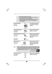
ATX 12V Power Connector (4-pin ATX12V1) (see p.11 No. 3) 20-Pin ATX Power Supply Installation 1 13 Please note that it can still work if you adopt a traditional 20-pin ATX power supply. Though this connector. Failing to connect a power supply with Pin 1 and Pin 13. To use the 20-pin ATX power supply, please plug your power supply along with ATX 12V plug to this motherboard provides 24-pin ATX power connector, 12 24 it is necessary to do so will cause power up failure. 23
ATX 12V Power Connector (4-pin ATX12V1) (see p.11 No. 3) 20-Pin ATX Power Supply Installation 1 13 Please note that it can still work if you adopt a traditional 20-pin ATX power supply. Though this connector. Failing to connect a power supply with Pin 1 and Pin 13. To use the 20-pin ATX power supply, please plug your power supply along with ATX 12V plug to this motherboard provides 24-pin ATX power connector, 12 24 it is necessary to do so will cause power up failure. 23

User Manual
Page 25
... end of the SATA data cable to the SATA / SATAII hard disk. 2 . 1 0 Hot Plug and Hot Swap Functions for SATA / SATAII HDDs This motherboard supports Hot Plug and Hot Swap functions for SATA / SATAII Devices. STEP 4: Connect the other end of the SATA data cable to the... that supports Serial ATA (SATA) / Serial ATAII (SATAII) hard disks and RAID functions. 2 . 9 Serial ATA (SATA) / Serial ATAII (SATAII) Hard Disks Installation This motherboard adopts NVIDIA® GeForce 7025 / nForce 630a chipset that it is called "Hot Plug" for the action to insert and remove the SATA / SATAII HDDs...
... end of the SATA data cable to the SATA / SATAII hard disk. 2 . 1 0 Hot Plug and Hot Swap Functions for SATA / SATAII HDDs This motherboard supports Hot Plug and Hot Swap functions for SATA / SATAII Devices. STEP 4: Connect the other end of the SATA data cable to the... that supports Serial ATA (SATA) / Serial ATAII (SATAII) hard disks and RAID functions. 2 . 9 Serial ATA (SATA) / Serial ATAII (SATAII) Hard Disks Installation This motherboard adopts NVIDIA® GeForce 7025 / nForce 630a chipset that it is called "Hot Plug" for the action to insert and remove the SATA / SATAII HDDs...


