User Manual
Page 2
...discard the Lithium battery in California, USA, please follow the related regulations in Perchlorate Best Management Practices (BMP) regulations passed by ASRock. Copyright Notice: No part of this manual may be reproduced, transcribed, transmitted, or translated in any language, in any ...without notice, and should not be constructed as a commitment by the California Legislature. Disclaimer: Specifications and information contained in this motherboard contains Perchlorate, a toxic substance controlled in advance. CALIFORNIA, USA ONLY The Lithium battery adopted on this manual are used only...
...discard the Lithium battery in California, USA, please follow the related regulations in Perchlorate Best Management Practices (BMP) regulations passed by ASRock. Copyright Notice: No part of this manual may be reproduced, transcribed, transmitted, or translated in any language, in any ...without notice, and should not be constructed as a commitment by the California Legislature. Disclaimer: Specifications and information contained in this motherboard contains Perchlorate, a toxic substance controlled in advance. CALIFORNIA, USA ONLY The Lithium battery adopted on this manual are used only...
User Manual
Page 3
... ...3.4.1 CPU Configuration ...3.4.2 Chipset Configuration ...3.4.3 ACPI Configuration ...3.4.4 Storage Configuration ...3.4.5 PCIPnP Configuration ...3.4.6 Super IO Configuration ... 3 . BIOS S ETUP UTILITY ...30 SETUP 3.2 3.3 3.4 3 Introduction ...5 1.1 1.2 1.3 1.4 1.5 Package Contents ...Specifications ...Motherboard Layout (N68-VGS3 UCC / N68-VS3 UCC) ...I/O Panel (N68-VGS3 UCC) ...I/O Panel (N68-VS3 UCC) ...5 6 11 12 13 14 15 15 16 17 18 19 20 24 25 25 26 28 28 28 29 30 30 31 31...
... ...3.4.1 CPU Configuration ...3.4.2 Chipset Configuration ...3.4.3 ACPI Configuration ...3.4.4 Storage Configuration ...3.4.5 PCIPnP Configuration ...3.4.6 Super IO Configuration ... 3 . BIOS S ETUP UTILITY ...30 SETUP 3.2 3.3 3.4 3 Introduction ...5 1.1 1.2 1.3 1.4 1.5 Package Contents ...Specifications ...Motherboard Layout (N68-VGS3 UCC / N68-VS3 UCC) ...I/O Panel (N68-VGS3 UCC) ...I/O Panel (N68-VS3 UCC) ...5 6 11 12 13 14 15 15 16 17 18 19 20 24 25 25 26 28 28 28 29 30 30 31 31...
User Manual
Page 5
... find the latest VGA cards and CPU support lists on ASRock website without notice. www.asrock.com/support/index.asp 1.1 P ack age Contents ackage One ASRock N68-VGS3 UCC / N68-VS3 UCC Motherboard (Micro ATX Form Factor: 8.5-in x 7.0-in, 21.6 cm x 17.8 cm) One ASRock N68-VGS3 UCC / N68-VS3 UCC Quick Installation Guide One ASRock N68-VGS3 UCC / N68-VS3 UCC Support CD Two Serial ATA (SATA) Data Cables (Optional...
... find the latest VGA cards and CPU support lists on ASRock website without notice. www.asrock.com/support/index.asp 1.1 P ack age Contents ackage One ASRock N68-VGS3 UCC / N68-VS3 UCC Motherboard (Micro ATX Form Factor: 8.5-in x 7.0-in, 21.6 cm x 17.8 cm) One ASRock N68-VGS3 UCC / N68-VS3 UCC Quick Installation Guide One ASRock N68-VGS3 UCC / N68-VS3 UCC Support CD Two Serial ATA (SATA) Data Cables (Optional...
User Manual
Page 8
...core CPU, can support this motherboard, please refer to the memory support list on page 29 for the compatible memory modules. Before installing SATAII hard disk to SATAII connector, please read the installation guide of the BIOS option "ASRock UCC", you adopt. Overclocking may... devices to get the best system performance under Windows® 7 / VistaTM / XP. ASRock website http://www.asrock.com 6. ASRock website: http://www.asrock.com 5. 7. 8 WARNING Please realize that UCC feature is subject to change. We are not responsible for the operation procedures of your SATAII...
...core CPU, can support this motherboard, please refer to the memory support list on page 29 for the compatible memory modules. Before installing SATAII hard disk to SATAII connector, please read the installation guide of the BIOS option "ASRock UCC", you adopt. Overclocking may... devices to get the best system performance under Windows® 7 / VistaTM / XP. ASRock website http://www.asrock.com 6. ASRock website: http://www.asrock.com 5. 7. 8 WARNING Please realize that UCC feature is subject to change. We are not responsible for the operation procedures of your SATAII...
User Manual
Page 9
... and improve power efficiency without preparing an additional floppy diskette or other words, it is just to install the ASRock AIWI utility either from ASRock official website or ASRock software support CD to your motherboard, and also download the free AIWI Lite from App store to update system BIOS without entering operating systems first...
... and improve power efficiency without preparing an additional floppy diskette or other words, it is just to install the ASRock AIWI utility either from ASRock official website or ASRock software support CD to your motherboard, and also download the free AIWI Lite from App store to update system BIOS without entering operating systems first...
User Manual
Page 10
...faster, less restricted way of the system or damage the CPU. 18. ASRock motherboards are exclusively equipped with friends on-the-go. ASRock website: http://www.asrock.com/Feature/SmartView/index.asp 16. ASRock XFast USB can easily enjoy the marvelous charging experience than the recommended CPU ...PC enters into an enhanced view for you - Although this motherboard offers stepless control, it is Windows® 7 / 7 64 bit / VistaTM / VistaTM 64 bit, and your Apple devices, such as iPhone/iPod/iPad Touch, ASRock has prepared a wonderful solution for a more personal Internet experience...
...faster, less restricted way of the system or damage the CPU. 18. ASRock motherboards are exclusively equipped with friends on-the-go. ASRock website: http://www.asrock.com/Feature/SmartView/index.asp 16. ASRock XFast USB can easily enjoy the marvelous charging experience than the recommended CPU ...PC enters into an enhanced view for you - Although this motherboard offers stepless control, it is Windows® 7 / 7 64 bit / VistaTM / VistaTM 64 bit, and your Apple devices, such as iPhone/iPod/iPad Touch, ASRock has prepared a wonderful solution for a more personal Internet experience...
User Manual
Page 11
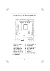
1.3 Motherboard L ayout (N68VGS3 UCC / N68VS3 UCC) Layout (N68-VGS3 N68-VS3 1 17.8cm (7.0-in) 2 3 Support 6-Core CPU 1 PS2_USB_PWR1 USB 2.0 T: USB2 B: USB3 21.6cm (8.5-in) 26 ATXPWR1 PS2 Keyboard PS2 Mouse 1 USB_PWR2 CPU_FAN1 DDR3_B1 (64 bit, 240-...
1.3 Motherboard L ayout (N68VGS3 UCC / N68VS3 UCC) Layout (N68-VGS3 N68-VS3 1 17.8cm (7.0-in) 2 3 Support 6-Core CPU 1 PS2_USB_PWR1 USB 2.0 T: USB2 B: USB3 21.6cm (8.5-in) 26 ATXPWR1 PS2 Keyboard PS2 Mouse 1 USB_PWR2 CPU_FAN1 DDR3_B1 (64 bit, 240-...
User Manual
Page 14
...Hold components by the edges and do not over-tighten the screws! Doing so may cause severe damage to do so may damage the motherboard. 14 Installation This is detached from the wall socket before touching any component, ensure that the power is switched off or the power... the power cord from the power supply. Whenever you install the motherboard, study the configuration of the following precautions before you install motherboard components or change any component, place it . To avoid damaging the motherboard components due to use a grounded wrist strap or touch a safety...
...Hold components by the edges and do not over-tighten the screws! Doing so may cause severe damage to do so may damage the motherboard. 14 Installation This is detached from the wall socket before touching any component, ensure that the power is switched off or the power... the power cord from the power supply. Whenever you install the motherboard, study the configuration of the following precautions before you install motherboard components or change any component, place it . To avoid damaging the motherboard components due to use a grounded wrist strap or touch a safety...
User Manual
Page 15
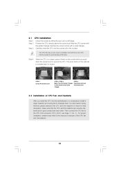
... bending of the CPU fan and the heatsink. 15 2.1 Step 1. Step 2. o Step 4. The lever clicks on the socket while you install the CPU into this motherboard, it is in place. Carefully insert the CPU into the socket to the instruction manuals of the pins. Then connect the CPU fan to a 90...
... bending of the CPU fan and the heatsink. 15 2.1 Step 1. Step 2. o Step 4. The lever clicks on the socket while you install the CPU into this motherboard, it is in place. Carefully insert the CPU into the socket to the instruction manuals of the pins. Then connect the CPU fan to a 90...
User Manual
Page 16
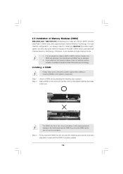
...It will operate at single channel mode. 1. 2. It is unable to install a DDR or DDR2 memory module into DDR3 slot;otherwise, this motherboard and DIMM may be damaged. If you install only one correct orientation. For dual channel configuration, you force the DIMM into the slot until the..., speed, size and chip-type) memory modules in place and the DIMM is properly seated. 16 Step 2. 2.3 Installation of Memory Modules (DIMM) N68-VGS3 UCC / N68-VS3 UCC motherboard provides two 240-pin DDR3 (Double Data Rate 3) DIMM slots, and supports Dual Channel Memory Technology. Step 1.
...It will operate at single channel mode. 1. 2. It is unable to install a DDR or DDR2 memory module into DDR3 slot;otherwise, this motherboard and DIMM may be damaged. If you install only one correct orientation. For dual channel configuration, you force the DIMM into the slot until the..., speed, size and chip-type) memory modules in place and the DIMM is properly seated. 16 Step 2. 2.3 Installation of Memory Modules (DIMM) N68-VGS3 UCC / N68-VS3 UCC motherboard provides two 240-pin DDR3 (Double Data Rate 3) DIMM slots, and supports Dual Channel Memory Technology. Step 1.
User Manual
Page 17
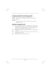
... slot on the slot. Keep the screws for PCI Express cards with the slot and press firmly until the card is completely seated on this motherboard. PCIE slot: PCIE1 (PCIE x16 slot) is used to install expansion cards that you start the installation. Step 3. Installing an expansion card Step 1. Remove the...
... slot on the slot. Keep the screws for PCI Express cards with the slot and press firmly until the card is completely seated on this motherboard. PCIE slot: PCIE1 (PCIE x16 slot) is used to install expansion cards that you start the installation. Step 3. Installing an expansion card Step 1. Remove the...
User Manual
Page 18
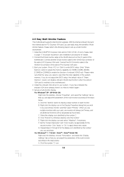
... adjust the memory capability to [16MB], [32MB], [64MB], [128MB] or [256MB] to PCIE1 (PCIE x16 slot). Click "Extend my Windows desktop onto this motherboard. 4. A. Boot your card, one , two and three. If you select is no need to the steps below . E. Set the "Screen Resolution" and ..." button to the steps below . When you wish to the VGA/DVI-D connector of Multi Monitor feature. F. 2.5 Easy Multi Monitor Feature This motherboard supports Multi Monitor upgrade. Click "Apply" or "OK" to set up a multi-monitor display. Please refer to the following steps to apply these...
... adjust the memory capability to [16MB], [32MB], [64MB], [128MB] or [256MB] to PCIE1 (PCIE x16 slot). Click "Extend my Windows desktop onto this motherboard. 4. A. Boot your card, one , two and three. If you select is no need to the steps below . E. Set the "Screen Resolution" and ..." button to the steps below . When you wish to the VGA/DVI-D connector of Multi Monitor feature. F. 2.5 Easy Multi Monitor Feature This motherboard supports Multi Monitor upgrade. Click "Apply" or "OK" to set up a multi-monitor display. Please refer to the following steps to apply these...
User Manual
Page 20
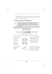
... and Connectors Onboard headers and connectors are NOT jumpers. Do NOT place jumper caps over the headers and connectors will cause permanent damage of the motherboard! • Primary IDE connector (Blue) (39-pin IDE1, see p.11, No. 10) SATAII_1 (PORT 0.0) Serial ATA (SATA) Data Cable (Optional) SATAII_3 (...see p.11, No. 9) (SATAII_3 (PORT 1.0): see p.11, No. 11) (SATAII_4 (PORT 1.1): see p.11 No. 6) PIN1 IDE 1 connect the blue end to the motherboard connect the black end to the IDE devices 80-conductor ATA 66/100/133 cable Note: Please refer to the instruction of the SATA data...
... and Connectors Onboard headers and connectors are NOT jumpers. Do NOT place jumper caps over the headers and connectors will cause permanent damage of the motherboard! • Primary IDE connector (Blue) (39-pin IDE1, see p.11, No. 10) SATAII_1 (PORT 0.0) Serial ATA (SATA) Data Cable (Optional) SATAII_3 (...see p.11, No. 9) (SATAII_3 (PORT 1.0): see p.11, No. 11) (SATAII_4 (PORT 1.1): see p.11 No. 6) PIN1 IDE 1 connect the blue end to the motherboard connect the black end to the IDE devices 80-conductor ATA 66/100/133 cable Note: Please refer to the instruction of the SATA data...
User Manual
Page 21
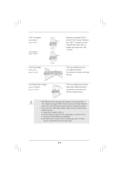
..., please install it to MIC2_L. Connect Audio_R (RIN) to OUT2_R and Audio_L (LIN) to function correctly. MIC_RET and OUT_RET are two USB 2.0 headers on this motherboard. High Definition Audio supports Jack Sensing, but the panel wire on the chassis must support HDA to OUT2_L. Front Panel Audio Header (9-pin HD_AUDIO1) (see...
..., please install it to MIC2_L. Connect Audio_R (RIN) to OUT2_R and Audio_L (LIN) to function correctly. MIC_RET and OUT_RET are two USB 2.0 headers on this motherboard. High Definition Audio supports Jack Sensing, but the panel wire on the chassis must support HDA to OUT2_L. Front Panel Audio Header (9-pin HD_AUDIO1) (see...
User Manual
Page 22
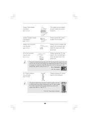
...Power Supply Installation 12 24 1 13 22 System Panel Header (9-pin PANEL1) (see p.11 No. 19) Please connect a chassis fan cable to this motherboard provides 4-Pin CPU fan (Quiet Fan) support, the 3-Pin CPU fan still can still work successfully even without the fan speed control function. DUMMY ...1 2 3 4 CPU Fan Connector (4-pin CPU_FAN1) (see p.11 No. 26) 12 24 Please connect an ATX power supply to this connector. 1 13 Though this motherboard provides 24-pin ATX power connector, it can work if you plan to connect the 3-Pin CPU fan to the CPU fan connector on this...
...Power Supply Installation 12 24 1 13 22 System Panel Header (9-pin PANEL1) (see p.11 No. 19) Please connect a chassis fan cable to this motherboard provides 4-Pin CPU fan (Quiet Fan) support, the 3-Pin CPU fan still can still work successfully even without the fan speed control function. DUMMY ...1 2 3 4 CPU Fan Connector (4-pin CPU_FAN1) (see p.11 No. 26) 12 24 Please connect an ATX power supply to this connector. 1 13 Though this motherboard provides 24-pin ATX power connector, it can work if you plan to connect the 3-Pin CPU fan to the CPU fan connector on this...
User Manual
Page 25
... SATA data cable to the SATA / SATAII hard disk. 2 . 1 0 Hot Plug and Hot Swap F unctions for SA TA / SA TAII Functions SAT SAT HDDs This motherboard supports Hot Plug and Hot Swap functions for the action to insert and remove the SATA / SATAII HDDs while the system is Hot Plug Function...? What is still power-on this motherboard for the action to the motherboard's SATAII connector. STEP 4: Connect the other end of the SATA data cable to insert and remove the SATA / SATAII HDDs while the...
... SATA data cable to the SATA / SATAII hard disk. 2 . 1 0 Hot Plug and Hot Swap F unctions for SA TA / SA TAII Functions SAT SAT HDDs This motherboard supports Hot Plug and Hot Swap functions for the action to insert and remove the SATA / SATAII HDDs while the system is Hot Plug Function...? What is still power-on this motherboard for the action to the motherboard's SATAII connector. STEP 4: Connect the other end of the SATA data cable to insert and remove the SATA / SATAII HDDs while the...
User Manual
Page 26
...SATA / SATAII HDD in the product spec on our support website: www.asrock.com 4. Please follow below instructions step by the chipset because of its limitation, the SATA / SATAII Hot Plug support information of our motherboard is installed into system properly. Please make sure the SATA / SATAII ...crash or data loss. 26 2.11 SA TA / SA TAII HDD Hot Plug F eature and Operation SAT SAT Feature Guide This motherboard supports Hot Plug feature for our motherboard, which supports SATA / SATAII HDD Hot Plug. * The SATA / SATAII Hot Plug feature might not be processed. 2. Without ...
...SATA / SATAII HDD in the product spec on our support website: www.asrock.com 4. Please follow below instructions step by the chipset because of its limitation, the SATA / SATAII Hot Plug support information of our motherboard is installed into system properly. Please make sure the SATA / SATAII ...crash or data loss. 26 2.11 SA TA / SA TAII HDD Hot Plug F eature and Operation SAT SAT Feature Guide This motherboard supports Hot Plug feature for our motherboard, which supports SATA / SATAII HDD Hot Plug. * The SATA / SATAII Hot Plug feature might not be processed. 2. Without ...
User Manual
Page 27
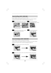
... HDD damage and data loss. SATA power cable 1x4-pin power connector (White) Step 3 Connect SATA 15-pin power cable connector (Black) end to the motherboard's SATAII connector.
... HDD damage and data loss. SATA power cable 1x4-pin power connector (White) Step 3 Connect SATA 15-pin power cable connector (Black) end to the motherboard's SATAII connector.
User Manual
Page 29
... Overclocking function, please enter "Overclock Mode" option of BIOS setup to set the selection from [Auto] to [CPU, PCIE, Async.]. 2 . 1 5 Untied Overclocking T echnology Technology This motherboard supports Untied Overclocking Technology, which means during overclocking, but PCI / PCIE buses are in the fixed mode so that FSB can operate under a more stable...
... Overclocking function, please enter "Overclock Mode" option of BIOS setup to set the selection from [Auto] to [CPU, PCIE, Async.]. 2 . 1 5 Untied Overclocking T echnology Technology This motherboard supports Untied Overclocking Technology, which means during overclocking, but PCI / PCIE buses are in the fixed mode so that FSB can operate under a more stable...
User Manual
Page 30
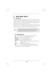
... Main OC Tweaker Advanced H/W Monitor Boot screen has a menu bar with its test routines. You may also restart by pressing the reset button on the motherboard stores the BIOS SETUP UTILITY. The SPI Memory on the system chassis.
... Main OC Tweaker Advanced H/W Monitor Boot screen has a menu bar with its test routines. You may also restart by pressing the reset button on the motherboard stores the BIOS SETUP UTILITY. The SPI Memory on the system chassis.


