
User Manual
Page 3
... UTILITY 22 3.1 Introduction 22 3.1.1 BIOS Menu Bar 22 3.1.2 Navigation Keys 23 3.2 Main Screen 23 3.3 OC Tweaker Screen 25 3.4 Advanced Screen 29 3.4.1 CPU Configuration 30 3.4.2 Chipset Configuration 31 3.4.3 ACPI Configuration 32 3.4.4 ...
... UTILITY 22 3.1 Introduction 22 3.1.1 BIOS Menu Bar 22 3.1.2 Navigation Keys 23 3.2 Main Screen 23 3.3 OC Tweaker Screen 25 3.4 Advanced Screen 29 3.4.1 CPU Configuration 30 3.4.2 Chipset Configuration 31 3.4.3 ACPI Configuration 32 3.4.4 ...

User Manual
Page 5
... the motherboard specifications and the BIOS software might be updated, the content of this motherboard, please visit our website for purchasing ASRock N68-GS4/USB3 FX R2.0 / N68-GS4 FX R2.0 motherboard, a reliable motherboard produced under ASRock's consistently stringent quality control. www.asrock.com/support/index.asp 1.1 Package Contents ASRock N68-GS4/USB3 FX R2.0 / N68-GS4 FX R2.0 Motherboard (Micro ATX Form Factor) ASRock N68-GS4/USB3 FX R2.0 / N68-GS4 FX R2.0X Quick Installation Guide ASRock N68-GS4/USB3 FX R2.0 / N68-GS4 FX R2.0 Support CD 2 x Serial ATA (SATA...
... the motherboard specifications and the BIOS software might be updated, the content of this motherboard, please visit our website for purchasing ASRock N68-GS4/USB3 FX R2.0 / N68-GS4 FX R2.0 motherboard, a reliable motherboard produced under ASRock's consistently stringent quality control. www.asrock.com/support/index.asp 1.1 Package Contents ASRock N68-GS4/USB3 FX R2.0 / N68-GS4 FX R2.0 Motherboard (Micro ATX Form Factor) ASRock N68-GS4/USB3 FX R2.0 / N68-GS4 FX R2.0X Quick Installation Guide ASRock N68-GS4/USB3 FX R2.0 / N68-GS4 FX R2.0 Support CD 2 x Serial ATA (SATA...

User Manual
Page 7
...N68-GS4 FX R2.0: - 1 x PS/2 Mouse Port - 1 x PS/2 Keyboard Port - 1 x Serial Port: COM1 - 1 x D-Sub Port - 4 x USB 2.0 Ports (Supports ESD Protection (ASRock Full Spike Protection)) - 1 x RJ-45 LAN Port with LED (ACT/LINK LED and SPEED LED) - CPU, VCCM, NB Voltage multi-adjustment 7 ACPI 1.1 Compliant wake up events - SMBIOS 2.3.1 support - AMI Legal BIOS...ASRock Full Spike Protection)) - 1 x USB 3.0 Header by Etron EJ188H (PCIE GEN1) (Supports 2 USB 3.0 ports) (Supports ESD Protection (ASRock Full Spike Protection)) (for N68-GS4/USB3 FX R2.0 only) - Supports PXE N68-GS4/USB3 FX R2...
...N68-GS4 FX R2.0: - 1 x PS/2 Mouse Port - 1 x PS/2 Keyboard Port - 1 x Serial Port: COM1 - 1 x D-Sub Port - 4 x USB 2.0 Ports (Supports ESD Protection (ASRock Full Spike Protection)) - 1 x RJ-45 LAN Port with LED (ACT/LINK LED and SPEED LED) - CPU, VCCM, NB Voltage multi-adjustment 7 ACPI 1.1 Compliant wake up events - SMBIOS 2.3.1 support - AMI Legal BIOS...ASRock Full Spike Protection)) - 1 x USB 3.0 Header by Etron EJ188H (PCIE GEN1) (Supports 2 USB 3.0 ports) (Supports ESD Protection (ASRock Full Spike Protection)) (for N68-GS4/USB3 FX R2.0 only) - Supports PXE N68-GS4/USB3 FX R2...
User Manual
Page 8
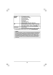
.../EuP ready power supply is required) * For detailed product information, please visit our website: http://www.asrock.com WARNING Please realize that there is a certain risk involved with overclocking, including adjusting the setting in the BIOS, applying Untied Overclocking Technology, or using the thirdparty overclocking tools. CPU temperature sensing Monitor - Hardware - Chassis...
.../EuP ready power supply is required) * For detailed product information, please visit our website: http://www.asrock.com WARNING Please realize that there is a certain risk involved with overclocking, including adjusting the setting in the BIOS, applying Untied Overclocking Technology, or using the thirdparty overclocking tools. CPU temperature sensing Monitor - Hardware - Chassis...
User Manual
Page 9
ASRock website http://www.asrock.com 4. This motherboard supports CPU up to enjoy an instant performance boost. If you want to adopt DDR3 1866/1600 memory module on this motherboard, ... Windows® 10 32-bit / 10 64-bit / 8.1 32-bit / 8.1 64-bit. ASRock UCC (Unlock CPU Core) feature simplifies AMD CPU activation. ASRock website http://www.asrock.com 2. This motherboard does not support RAID mode with HDDs of the BIOS option "ASRock UCC", you can unlock the extra CPU core to 6MB, which means you...
ASRock website http://www.asrock.com 4. This motherboard supports CPU up to enjoy an instant performance boost. If you want to adopt DDR3 1866/1600 memory module on this motherboard, ... Windows® 10 32-bit / 10 64-bit / 8.1 32-bit / 8.1 64-bit. ASRock UCC (Unlock CPU Core) feature simplifies AMD CPU activation. ASRock website http://www.asrock.com 2. This motherboard does not support RAID mode with HDDs of the BIOS option "ASRock UCC", you can unlock the extra CPU core to 6MB, which means you...
User Manual
Page 10
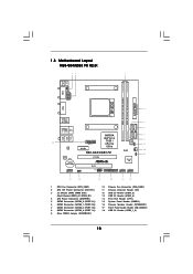
...N68-GS4/USB3 FX R2.0: 12 3 PS2 Mouse PS2 Keyboard COM1 ATXPWR1 DDR3_B1 (64 bit, 240-pin module) DDR3_A1 (64 bit, 240-FpinSBmo8d0ul0e) CPU_FAN1 ATX12V1 4 SOCKET AM3 VGA1 USB 3.0 T: USB3 B: USB4 5 SATAII_3 (PORT 1.0) SATAII_1 (PORT 0.0) SATAII_2 (PORT 0.1) 6 USB 2.0 T: USB3 B: USB4 Top: RJ-45 SATAII_4 (PORT 1.1) NVIDIA 7 Top: LINE IN Center: FRONT Bottom: MIC IN GeForce 8 7025 / BIOS... 18 USB3_1_2 nForce ROM 9 CLRCMOS1 LAN PHY PCIE1 630a 1 CHA_FAN1 RoHS 10 N68-GS4/USB3 FX CI1 11 AUDIO CODEC CMOS BATTERY PCIE2 1...
...N68-GS4/USB3 FX R2.0: 12 3 PS2 Mouse PS2 Keyboard COM1 ATXPWR1 DDR3_B1 (64 bit, 240-pin module) DDR3_A1 (64 bit, 240-FpinSBmo8d0ul0e) CPU_FAN1 ATX12V1 4 SOCKET AM3 VGA1 USB 3.0 T: USB3 B: USB4 5 SATAII_3 (PORT 1.0) SATAII_1 (PORT 0.0) SATAII_2 (PORT 0.1) 6 USB 2.0 T: USB3 B: USB4 Top: RJ-45 SATAII_4 (PORT 1.1) NVIDIA 7 Top: LINE IN Center: FRONT Bottom: MIC IN GeForce 8 7025 / BIOS... 18 USB3_1_2 nForce ROM 9 CLRCMOS1 LAN PHY PCIE1 630a 1 CHA_FAN1 RoHS 10 N68-GS4/USB3 FX CI1 11 AUDIO CODEC CMOS BATTERY PCIE2 1...
User Manual
Page 11
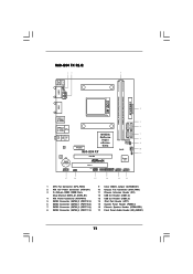
N68-GS4 FX R2.0: 12 3 PS2 Mouse PS2 Keyboard COM1 ATXPWR1 DDR3_B1 (64 bit, 240-pin module) DDR3_A1 (64 bit, 240-FpinSBmo8d0ul0e) CPU_FAN1 ATX12V1 4 SOCKET AM3 VGA1 Top: LINE IN Center: FRONT Bottom: MIC IN USB 2.0 T: USB1 B: USB2 5 SATAII_1 (PORT 0.0) SATAII_2 (PORT 0.1) 6 USB 2.0 T: USB3... B: USB4 Top: RJ-45 SATAII_3 (PORT 1.0) SATAII_4 (PORT 1.1) LAN PHY AUDIO CODEC CMOS BATTERY PCIE1 NVIDIA GeForce 7025 / nForce 630a N68-GS4 FX PCIE2 PCI1 7 8 BIOS ROM CLRCMOS1 1 CHA_FAN1 RoHS 9 10 CI1 11 1 Super ...
N68-GS4 FX R2.0: 12 3 PS2 Mouse PS2 Keyboard COM1 ATXPWR1 DDR3_B1 (64 bit, 240-pin module) DDR3_A1 (64 bit, 240-FpinSBmo8d0ul0e) CPU_FAN1 ATX12V1 4 SOCKET AM3 VGA1 Top: LINE IN Center: FRONT Bottom: MIC IN USB 2.0 T: USB1 B: USB2 5 SATAII_1 (PORT 0.0) SATAII_2 (PORT 0.1) 6 USB 2.0 T: USB3... B: USB4 Top: RJ-45 SATAII_3 (PORT 1.0) SATAII_4 (PORT 1.1) LAN PHY AUDIO CODEC CMOS BATTERY PCIE1 NVIDIA GeForce 7025 / nForce 630a N68-GS4 FX PCIE2 PCI1 7 8 BIOS ROM CLRCMOS1 1 CHA_FAN1 RoHS 9 10 CI1 11 1 Super ...
User Manual
Page 18
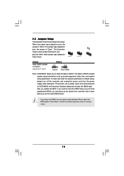
... system setup parameters. The illustration shows a 3-pin jumper whose pin1 and pin2 are setup. Please adjust the BIOS option "Clear Status" to default setup, please turn off the computer and unplug the power cord from the ...intrusion status. 18 If you need to clear the CMOS when you just finish updating the BIOS, you must boot up the system first, and then shut it down before you do not clear... the CMOS right after you update the BIOS. However, please do the clear-CMOS action. Jumper Clear CMOS Jumper (CLRCMOS1) (see p.10 or 11...
... system setup parameters. The illustration shows a 3-pin jumper whose pin1 and pin2 are setup. Please adjust the BIOS option "Clear Status" to default setup, please turn off the computer and unplug the power cord from the ...intrusion status. 18 If you need to clear the CMOS when you just finish updating the BIOS, you must boot up the system first, and then shut it down before you do not clear... the CMOS right after you update the BIOS. However, please do the clear-CMOS action. Jumper Clear CMOS Jumper (CLRCMOS1) (see p.10 or 11...
User Manual
Page 22
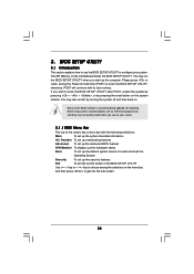
... they may not exactly match what you start up the security features Exit To exit the current screen or the BIOS SETUP UTILITY Use < > key or < > key to enter the BIOS SETUP UTILITY, otherwise, POST will continue with its test routines. Please press or during the Power-On-Self-Test...following selections: Main To set up the system time/date information OC Tweaker To set up overclocking features Advanced To set up the advanced BIOS features H/W Monitor To display current hardware status Boot To set up the default system device to locate and load the Operating System Security To...
... they may not exactly match what you start up the security features Exit To exit the current screen or the BIOS SETUP UTILITY Use < > key or < > key to enter the BIOS SETUP UTILITY, otherwise, POST will continue with its test routines. Please press or during the Power-On-Self-Test...following selections: Main To set up the system time/date information OC Tweaker To set up overclocking features Advanced To set up the advanced BIOS features H/W Monitor To display current hardware status Boot To set up the default system device to locate and load the Operating System Security To...

User Manual
Page 23
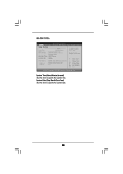
... to specify the system date. 23 Use [+] or [-] to select a field. N68-GS4/USB3 FX R2.0: BIOS SETUP UTILITY Main OC Tweaker Advanced H/W Monitor Boot Security Exit System Overview System Time System Date [17:00:09] [Thu 08/10/2015] BIOS Version : N68-GS4/USB3 FX R2.0 P1.00 Processor Type : AMD Athlon (tm) II X3 440 Processor (64bit)... description of each navigation key. 3.1.2Navigation Keys Please check the following table for all the settings To save changes and exit the BIOS SETUP UTILITY To jump to the Exit Screen or exit the current screen 3.2 Main Screen When you enter the...
... to specify the system date. 23 Use [+] or [-] to select a field. N68-GS4/USB3 FX R2.0: BIOS SETUP UTILITY Main OC Tweaker Advanced H/W Monitor Boot Security Exit System Overview System Time System Date [17:00:09] [Thu 08/10/2015] BIOS Version : N68-GS4/USB3 FX R2.0 P1.00 Processor Type : AMD Athlon (tm) II X3 440 Processor (64bit)... description of each navigation key. 3.1.2Navigation Keys Please check the following table for all the settings To save changes and exit the BIOS SETUP UTILITY To jump to the Exit Screen or exit the current screen 3.2 Main Screen When you enter the...
User Manual
Page 24
... Main OC Tweaker Advanced H/W Monitor Boot Security Exit System Overview System Time System Date [17:00:09] [Thu 08/10/2015] BIOS Version : N68-GS4 FX R2.0 P1.00 Processor Type : AMD Athlon (tm) II X3 440 Processor (64bit) Processor Speed : 3000MHz Microcode Update : 100F52/1000086 L1 Cache Size : 384KB L2 Cache ...
... Main OC Tweaker Advanced H/W Monitor Boot Security Exit System Overview System Time System Date [17:00:09] [Thu 08/10/2015] BIOS Version : N68-GS4 FX R2.0 P1.00 Processor Type : AMD Athlon (tm) II X3 440 Processor (64bit) Processor Speed : 3000MHz Microcode Update : 100F52/1000086 L1 Cache Size : 384KB L2 Cache ...

User Manual
Page 25
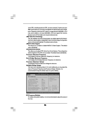
... Overclock Mode CPU Frequency (MHz) PCIE Frequency (MHz) Boot Failure Guard Boot Failure Guard Count CPU/LDT Spread Spectrum PCIE Spread Spectrum SATA Spread Spectrum ASRock UCC AMD Turbo Core Technology AMD IO C-State Support CPU Active Core Control [Auto] [200] [100] [Enabled] [3] [Enabled] [Enabled] [Enabled]... features. It should be set to [Enabled] as a simple switch of the BIOS option "ASRock UCC", you can unlock the extra CPU core to your own risk and expense. ASRock UCC ASRock UCC (Unlock CPU Core) feature simplifies AMD CPU activation. CPU Configuration Overclock Mode...
... Overclock Mode CPU Frequency (MHz) PCIE Frequency (MHz) Boot Failure Guard Boot Failure Guard Count CPU/LDT Spread Spectrum PCIE Spread Spectrum SATA Spread Spectrum ASRock UCC AMD Turbo Core Technology AMD IO C-State Support CPU Active Core Control [Auto] [200] [100] [Enabled] [3] [Enabled] [Enabled] [Enabled]... features. It should be set to [Enabled] as a simple switch of the BIOS option "ASRock UCC", you can unlock the extra CPU core to your own risk and expense. ASRock UCC ASRock UCC (Unlock CPU Core) feature simplifies AMD CPU activation. CPU Configuration Overclock Mode...
User Manual
Page 26
...the processor you adopt. Processor Maximum Frequency It will display Processor Maximum Frequency for reference. The default value is [Enabled]. BIOS SETUP UTILITY Main OC Tweaker Advanced H/W Monitor Boot Security Exit CPU Configuration Overclock Mode CPU Frequency (MHz) PCIE Frequency ...(MHz) Boot Failure Guard Boot Failure Guard Count CPU/LDT Spread Spectrum PCIE Spread Spectrum SATA Spread Spectrum ASRock UCC AMD Turbo Core Technology AMD IO C-State Support CPU Active Core Control [Auto] [200] [100] [Enabled] [3] [Enabled] [Enabled]...
...the processor you adopt. Processor Maximum Frequency It will display Processor Maximum Frequency for reference. The default value is [Enabled]. BIOS SETUP UTILITY Main OC Tweaker Advanced H/W Monitor Boot Security Exit CPU Configuration Overclock Mode CPU Frequency (MHz) PCIE Frequency ...(MHz) Boot Failure Guard Boot Failure Guard Count CPU/LDT Spread Spectrum PCIE Spread Spectrum SATA Spread Spectrum ASRock UCC AMD Turbo Core Technology AMD IO C-State Support CPU Active Core Control [Auto] [200] [100] [Enabled] [3] [Enabled] [Enabled]...
User Manual
Page 27
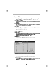
... is not recommended to enable or disable DDR power down mode. DRAM Voltage Use this item to adjust the value of this item. Memory Timing BIOS SETUP UTILITY OC Tweaker Memory Timing Power Down Enable Bank Interleaving Channel Interleaving CAS Latency (CL) TRCD TRP TRAS Command Rate TRC TRTP TWR TRFC...
... is not recommended to enable or disable DDR power down mode. DRAM Voltage Use this item to adjust the value of this item. Memory Timing BIOS SETUP UTILITY OC Tweaker Memory Timing Power Down Enable Bank Interleaving Channel Interleaving CAS Latency (CL) TRCD TRP TRAS Command Rate TRC TRTP TWR TRFC...
User Manual
Page 29
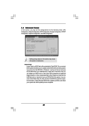
... the following items: CPU Configuration, Chipset Configuration, ACPI Configuration, Storage Configuration, PCIPnP Configuration, SuperIO Configuration, and USB Configuration. BIOS SETUP UTILITY Main OC Tweaker Advanced H/W Monitor Boot Security Exit Advanced Settings Options for CPU WARNING : Setting wrong values in ...this section, you can update your BIOS only in Flash ROM. Just launch this tool and save the new BIOS file to your system after BIOS update process completes. 29 CPU Configuration Chipset Configuration ACPI Configuration Storage...
... the following items: CPU Configuration, Chipset Configuration, ACPI Configuration, Storage Configuration, PCIPnP Configuration, SuperIO Configuration, and USB Configuration. BIOS SETUP UTILITY Main OC Tweaker Advanced H/W Monitor Boot Security Exit Advanced Settings Options for CPU WARNING : Setting wrong values in ...this section, you can update your BIOS only in Flash ROM. Just launch this tool and save the new BIOS file to your system after BIOS update process completes. 29 CPU Configuration Chipset Configuration ACPI Configuration Storage...
User Manual
Page 30
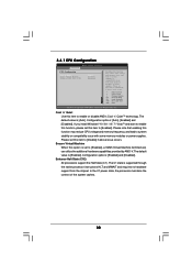
... [Enabled]. Please set to [Enabled], a VMM (Virtual Machine Architecture) can utilize the additional hardware capabilities provided by AMD-V. Configuration options: [Enabled] and [Disabled]. 3.4.1 CPU Configuration BIOS SETUP UTILITY Advanced CPU Configuration Cool 'n' Quiet Secure Virtual Machine Enhanced Halt State (C1E) [Auto] [Enabled] [Disabled] Enabling this function may reduce CPU voltage and...
... [Enabled]. Please set to [Enabled], a VMM (Virtual Machine Architecture) can utilize the additional hardware capabilities provided by AMD-V. Configuration options: [Enabled] and [Disabled]. 3.4.1 CPU Configuration BIOS SETUP UTILITY Advanced CPU Configuration Cool 'n' Quiet Secure Virtual Machine Enhanced Halt State (C1E) [Auto] [Enabled] [Disabled] Enabling this function may reduce CPU voltage and...
User Manual
Page 31
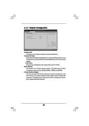
Primary Graphics Adapter This item will be disabled when PCI Sound Card is plugged. The default value of multiple video controllers. 3.4.2 Chipset Configuration BIOS SETUP UTILITY Advanced Chipset Settings Onboard LAN Onboard HD Audio Front Panel Share Memory Primary Graphics Adapter [Enabled] [Auto] [Auto] [Auto] [PCI] Auto/Enable/Disable ...
Primary Graphics Adapter This item will be disabled when PCI Sound Card is plugged. The default value of multiple video controllers. 3.4.2 Chipset Configuration BIOS SETUP UTILITY Advanced Chipset Settings Onboard LAN Onboard HD Audio Front Panel Share Memory Primary Graphics Adapter [Enabled] [Auto] [Auto] [Auto] [PCI] Auto/Enable/Disable ...
User Manual
Page 32
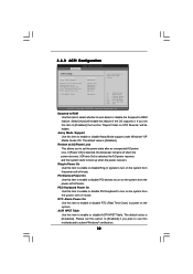
...]. The default value is selected, the AC/power remains off mode. RTC Alarm Power On Use this feature if the OS supports it. 3.4.3 ACPI Configuration BIOS SETUP UTILITY Advanced ACPI Settings Suspend To RAM Away Mode Support Restore on the system. Restore on the system from the power-soft-off mode...
...]. The default value is selected, the AC/power remains off mode. RTC Alarm Power On Use this feature if the OS supports it. 3.4.3 ACPI Configuration BIOS SETUP UTILITY Advanced ACPI Settings Suspend To RAM Away Mode Support Restore on the system. Restore on the system from the power-soft-off mode...
User Manual
Page 33
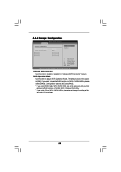
... [RAID]. * If you select [RAID] mode, SATA / SATAII HDDs can not be accessed until you finish configuring RAID functions in NVIDIA BIOS / Windows RAID Utility. * If you want to enable or disable the "Onboard SATA Controller" feature. If you install OS on SATA /... SATAII HDDs, please select [RAID]. 3.4.4 Storage Configuration BIOS SETUP UTILITY Advanced Storage Configuration Onboard SATA Controller SATA Operation Mode SATAII_1 SATAII_2 SATAII_3 SATAII_4 [Enabled] [IDE] [Not Detected] [Not Detected] [Not...
... [RAID]. * If you select [RAID] mode, SATA / SATAII HDDs can not be accessed until you finish configuring RAID functions in NVIDIA BIOS / Windows RAID Utility. * If you want to enable or disable the "Onboard SATA Controller" feature. If you install OS on SATA /... SATAII HDDs, please select [RAID]. 3.4.4 Storage Configuration BIOS SETUP UTILITY Advanced Storage Configuration Onboard SATA Controller SATA Operation Mode SATAII_1 SATAII_2 SATAII_3 SATAII_4 [Enabled] [IDE] [Not Detected] [Not Detected] [Not...
User Manual
Page 34
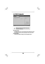
... recommended to enable or disable the PCI IDE BusMaster feature. 34 PCI IDE BusMaster Use this section may cause the system to malfunction. 3.4.5 PCIPnP Configuration BIOS SETUP UTILITY Advanced Advanced PCI / PnP Settings PCI Latency Timer PCI IDE BusMaster [32] [Enabled] Value in this item to keep the default value unless...
... recommended to enable or disable the PCI IDE BusMaster feature. 34 PCI IDE BusMaster Use this section may cause the system to malfunction. 3.4.5 PCIPnP Configuration BIOS SETUP UTILITY Advanced Advanced PCI / PnP Settings PCI Latency Timer PCI IDE BusMaster [32] [Enabled] Value in this item to keep the default value unless...


