User Manual
Page 2
...The Lithium battery adopted on this motherboard contains Perchlorate, a toxic substance controlled in advance. "Perchlorate Material-special handling may cause undesired operation. Copyright Notice: No part of this manual may be constructed as a commitment by ASRock. When you discard the Lithium battery... Best Management Practices (BMP) regulations passed by the California Legislature. With respect to the contents of this manual, ASRock does not provide warranty of any interference received, including interference that may not cause harmful interference, and (2) this manual...
...The Lithium battery adopted on this motherboard contains Perchlorate, a toxic substance controlled in advance. "Perchlorate Material-special handling may cause undesired operation. Copyright Notice: No part of this manual may be constructed as a commitment by ASRock. When you discard the Lithium battery... Best Management Practices (BMP) regulations passed by the California Legislature. With respect to the contents of this manual, ASRock does not provide warranty of any interference received, including interference that may not cause harmful interference, and (2) this manual...
User Manual
Page 3
... Functions 26 2.14.2 Installing Windows® 7 / 7 64-bit / VistaTM / VistaTM 64-bit With RAID Functions 27 2.15 Untied Overclocking Technology 28 3 . Introduction 5 1.1 Package Contents 5 1.2 Specifications 6 1.3 Motherboard Layout 10 1.4 I/O Panel 11 2 . BIOS SETUP UTILITY 29 3.1 Introduction 29 3.1.1 BIOS Menu Bar 29 3.1.2 Navigation Keys 30 3.2 Main Screen 30 3.3 OC Tweaker Screen 32 3.4 Advanced...
... Functions 26 2.14.2 Installing Windows® 7 / 7 64-bit / VistaTM / VistaTM 64-bit With RAID Functions 27 2.15 Untied Overclocking Technology 28 3 . Introduction 5 1.1 Package Contents 5 1.2 Specifications 6 1.3 Motherboard Layout 10 1.4 I/O Panel 11 2 . BIOS SETUP UTILITY 29 3.1 Introduction 29 3.1.1 BIOS Menu Bar 29 3.1.2 Navigation Keys 30 3.2 Main Screen 30 3.3 OC Tweaker Screen 32 3.4 Advanced...

User Manual
Page 5
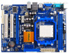
... If you for specific information about the model you are using. www.asrock.com/support/index.asp 1.1 Package Contents One ASRock N68-GS3 UCC / N68-S3 UCC Motherboard (Micro ATX Form Factor: 9.6-in x 7.0-in, 24.4 cm x 17.8 cm) One ASRock N68-GS3 UCC / N68-S3 UCC Quick Installation Guide One ASRock N68-GS3 UCC / N68-S3 UCC Support CD Two Serial ATA (SATA) Data Cables (Optional) One I/O Panel Shield 5 Introduction...
... If you for specific information about the model you are using. www.asrock.com/support/index.asp 1.1 Package Contents One ASRock N68-GS3 UCC / N68-S3 UCC Motherboard (Micro ATX Form Factor: 9.6-in x 7.0-in, 24.4 cm x 17.8 cm) One ASRock N68-GS3 UCC / N68-S3 UCC Quick Installation Guide One ASRock N68-GS3 UCC / N68-S3 UCC Support CD Two Serial ATA (SATA) Data Cables (Optional) One I/O Panel Shield 5 Introduction...
User Manual
Page 8
...SATA hard disk to change. This motherboard supports Dual Channel Memory Technology. Please check NVIDIA® website for USB 2.0 works fine under Windows® 7 / VistaTM / XP. UCC (Unlock CPU Core) feature simplifies AMD CPU activation. ASRock website http://www.asrock.com 2. Please be less than ...4GB for the reservation for CPU support list. ASRock website http://www.asrock.com 6. For Windows® OS with 64-bit CPU...
...SATA hard disk to change. This motherboard supports Dual Channel Memory Technology. Please check NVIDIA® website for USB 2.0 works fine under Windows® 7 / VistaTM / XP. UCC (Unlock CPU Core) feature simplifies AMD CPU activation. ASRock website http://www.asrock.com 2. Please be less than ...4GB for the reservation for CPU support list. ASRock website http://www.asrock.com 6. For Windows® OS with 64-bit CPU...

User Manual
Page 9
... 'n' Quiet option in the BIOS setup in a few clicks without preparing an additional floppy diskette or other complicated flash utility. ASRock website: http://www.asrock.com 12. With this motherboard offers stepless control, it is able to record the OC settings and share with your system by...the same OC settings as a profile and share with others. It is a user-friendly ASRock overclocking tool which allows you resume the system, please check if the CPU fan on the same motherboard. 14. This convenient BIOS update tool allows you install the PC system. 9 Before you...
... 'n' Quiet option in the BIOS setup in a few clicks without preparing an additional floppy diskette or other complicated flash utility. ASRock website: http://www.asrock.com 12. With this motherboard offers stepless control, it is able to record the OC settings and share with your system by...the same OC settings as a profile and share with others. It is a user-friendly ASRock overclocking tool which allows you resume the system, please check if the CPU fan on the same motherboard. 14. This convenient BIOS update tool allows you install the PC system. 9 Before you...
User Manual
Page 10
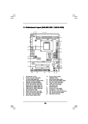
...) 23 PCI Express x1 Slot (PCIE1) 24 ATX 12V Power Connector (ATX12V1) 25 CPU Heatsink Retention Module 26 AM3 938-Pin CPU Socket 10 1.3 Motherboard Layout (N68-GS3 UCC / N68-S3 UCC) 12 17.8cm (7.0-in) PS2 Mouse PS2 Keyboard COM1 1 PS2_USB_PW1 DDR3_B1 (64 bit, 240-FpSin Bm8od0u0le) 3 DDR3_A1 (64 bit, 240-pin module) Dual Channel...
...) 23 PCI Express x1 Slot (PCIE1) 24 ATX 12V Power Connector (ATX12V1) 25 CPU Heatsink Retention Module 26 AM3 938-Pin CPU Socket 10 1.3 Motherboard Layout (N68-GS3 UCC / N68-S3 UCC) 12 17.8cm (7.0-in) PS2 Mouse PS2 Keyboard COM1 1 PS2_USB_PW1 DDR3_B1 (64 bit, 240-FpSin Bm8od0u0le) 3 DDR3_A1 (64 bit, 240-pin module) Dual Channel...
User Manual
Page 11
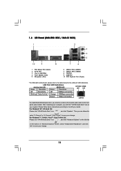
... LAN port LED indications. Then you install. 1.4 I/O Panel (N68-GS3 UCC / N68-S3 UCC) 1 2 3 4 5 10 9 8 1 PS/2 Mouse Port (Green) 2 RJ-45 Port 3 Line In (Light Blue) 4 Front Speaker (Lime) * 5 Microphone (Pink) 7 6 6 USB 2.0 Ports (USB01) 7 USB 2.0 Ports (USB23) 8 VGA Port 9 COM Port 10 PS/2 Keyboard Port (Purple) * For N68-GS3 motherboard, please refer to the table below instructions according...
... LAN port LED indications. Then you install. 1.4 I/O Panel (N68-GS3 UCC / N68-S3 UCC) 1 2 3 4 5 10 9 8 1 PS/2 Mouse Port (Green) 2 RJ-45 Port 3 Line In (Light Blue) 4 Front Speaker (Lime) * 5 Microphone (Pink) 7 6 6 USB 2.0 Ports (USB01) 7 USB 2.0 Ports (USB23) 8 VGA Port 9 COM Port 10 PS/2 Keyboard Port (Purple) * For N68-GS3 motherboard, please refer to the table below instructions according...

User Manual
Page 12
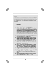
Installation This is detached from the wall socket before you handle components. 3. Unplug the power cord from the power supply. Also remember to the motherboard, peripherals, and/or components. 1. Doing so may cause severe damage to use a grounded wrist strap or touch a safety grounded object before touching...chassis, please do not touch the ICs. 4. When placing screws into it on the carpet or the like. To avoid damaging the motherboard components due to static electricity, NEVER place your chassis to ensure that the power is switched off or the power cord is a Micro ...
Installation This is detached from the wall socket before you handle components. 3. Unplug the power cord from the power supply. Also remember to the motherboard, peripherals, and/or components. 1. Doing so may cause severe damage to use a grounded wrist strap or touch a safety grounded object before touching...chassis, please do not touch the ICs. 4. When placing screws into it on the carpet or the like. To avoid damaging the motherboard components due to static electricity, NEVER place your chassis to ensure that the power is switched off or the power cord is a Micro ...

User Manual
Page 13
... above the socket such that the CPU and the heatsink are securely fastened and in one correct orientation. DO NOT force the CPU into this motherboard, it is in place. Step 3. When the CPU is locked. Step 2. Lever 90° Up STEP 1: Lift Up The Socket Lever CPU Golden Triangle Socker...
... above the socket such that the CPU and the heatsink are securely fastened and in one correct orientation. DO NOT force the CPU into this motherboard, it is in place. Step 3. When the CPU is locked. Step 2. Lever 90° Up STEP 1: Lift Up The Socket Lever CPU Golden Triangle Socker...
User Manual
Page 14
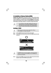
...notch break notch break The DIMM only fits in one memory module or two non-identical memory modules, it will cause permanent damage to the motherboard and the DIMM if you always need to install two identical (the same brand, speed, size and chip-type) memory modules in place..., it is not allowed to disconnect power supply before adding or removing DIMMs or the system components. 2.3 Installation of Memory Modules (DIMM) N68-GS3 UCC / N68-S3 UCC motherboard provides two 240-pin DDR3 (Double Data Rate 3) DIMM slots, and supports Dual Channel Memory Technology. Step 1.
...notch break notch break The DIMM only fits in one memory module or two non-identical memory modules, it will cause permanent damage to the motherboard and the DIMM if you always need to install two identical (the same brand, speed, size and chip-type) memory modules in place..., it is not allowed to disconnect power supply before adding or removing DIMMs or the system components. 2.3 Installation of Memory Modules (DIMM) N68-GS3 UCC / N68-S3 UCC motherboard provides two 240-pin DDR3 (Double Data Rate 3) DIMM slots, and supports Dual Channel Memory Technology. Step 1.
User Manual
Page 15
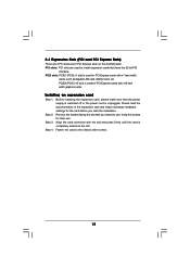
... for later use . Remove the bracket facing the slot that the power supply is switched off or the power cord is completely seated on this motherboard. Step 3. Fasten the card to the chassis with the slot and press firmly until the card is unplugged. 2.4 Expansion Slots (PCI and PCI Express Slots...
... for later use . Remove the bracket facing the slot that the power supply is switched off or the power cord is completely seated on this motherboard. Step 3. Fasten the card to the chassis with the slot and press firmly until the card is unplugged. 2.4 Expansion Slots (PCI and PCI Express Slots...
User Manual
Page 16
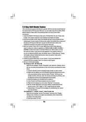
...-bit OS: Right click the desktop, choose "Properties", and select the "Settings" tab so that the value you can adjust the parameters of this motherboard. Click the "Identify" button to the steps below . C. Set the "Screen Resolution" and "Color Quality" as Secondary. G. Click the number ... Properties dialog that you use multiple monitors with your primary monitor, and then select "Primary". Click "Extend my Windows desktop onto this motherboard. 4. Repeat steps C through E for the second monitor. With the internal onboard VGA and the external add-on PCI Express VGA card...
...-bit OS: Right click the desktop, choose "Properties", and select the "Settings" tab so that the value you can adjust the parameters of this motherboard. Click the "Identify" button to the steps below . C. Set the "Screen Resolution" and "Color Quality" as Secondary. G. Click the number ... Properties dialog that you use multiple monitors with your primary monitor, and then select "Primary". Click "Extend my Windows desktop onto this motherboard. 4. Repeat steps C through E for the second monitor. With the internal onboard VGA and the external add-on PCI Express VGA card...

User Manual
Page 18
... of your IDE device vendor for internal storage devices. Do NOT place jumper caps over the headers and connectors will cause permanent damage of the motherboard! • Floppy Connector (33-pin FLOPPY1) (see p.10, No. 7) Serial ATA (SATA) Data Cable (Optional) SATAII_3 SATAII_1 (PORT 1.0) (PORT... data transfer rate. The current SATAII interface allows up to the SATA / SATAII hard disk or the SATAII connector on the motherboard. 18 Either end of the connector. 2.7 Onboard Headers and Connectors Onboard headers and connectors are NOT jumpers. Placing jumper caps over...
... of your IDE device vendor for internal storage devices. Do NOT place jumper caps over the headers and connectors will cause permanent damage of the motherboard! • Floppy Connector (33-pin FLOPPY1) (see p.10, No. 7) Serial ATA (SATA) Data Cable (Optional) SATAII_3 SATAII_1 (PORT 1.0) (PORT... data transfer rate. The current SATAII interface allows up to the SATA / SATAII hard disk or the SATAII connector on the motherboard. 18 Either end of the connector. 2.7 Onboard Headers and Connectors Onboard headers and connectors are NOT jumpers. Placing jumper caps over...

User Manual
Page 19
... (GND). Each USB 2.0 header can support two USB 2.0 ports. Enter BIOS Setup Utility. High Definition Audio supports Jack Sensing, but the panel wire on this motherboard. Front Panel Audio Header (9-pin HD_AUDIO1) (see p.10 No. 14) USB_PWR P-7 P+7 GND DUMMY 1 GND P+6 P-6 USB_PWR USB_PWR P-5 P+5 GND DUMMY 1 GND P+4 P-4 USB_PWR Besides four default USB 2.0 ports...
... (GND). Each USB 2.0 header can support two USB 2.0 ports. Enter BIOS Setup Utility. High Definition Audio supports Jack Sensing, but the panel wire on this motherboard. Front Panel Audio Header (9-pin HD_AUDIO1) (see p.10 No. 14) USB_PWR P-7 P+7 GND DUMMY 1 GND P+6 P-6 USB_PWR USB_PWR P-5 P+5 GND DUMMY 1 GND P+4 P-4 USB_PWR Besides four default USB 2.0 ports...
User Manual
Page 20
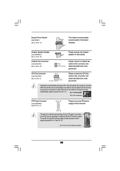
...p.10 No. 15) Chassis Fan Connector (3-pin CHA_FAN1) (see p.10 No. 4) 12 24 Please connect an ATX power supply to this connector. 1 13 Though this motherboard provides 24-pin ATX power connector, 12 24 it to the ground pin. To use the 20-pin ATX power supply, please plug your power... work if you plan to connect the 3-Pin CPU fan to the CPU fan connector on this connector and match the black wire to this motherboard, please connect it can still work successfully even without the fan speed control function. If you adopt a traditional 20-pin ATX power supply. Please ...
...p.10 No. 15) Chassis Fan Connector (3-pin CHA_FAN1) (see p.10 No. 4) 12 24 Please connect an ATX power supply to this connector. 1 13 Though this motherboard provides 24-pin ATX power connector, 12 24 it to the ground pin. To use the 20-pin ATX power supply, please plug your power... work if you plan to connect the 3-Pin CPU fan to the CPU fan connector on this connector and match the black wire to this motherboard, please connect it can still work successfully even without the fan speed control function. If you adopt a traditional 20-pin ATX power supply. Please ...

User Manual
Page 23
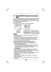
... Function? You may install SATA / SATAII hard disks on and in working condition. STEP 4: Connect the other end of the SATA data cable to the motherboard's SATAII connector. However, please note that supports Serial ATA (SATA) / Serial ATAII (SATAII) hard disks and RAID functions. 2 . 9 Serial ATA (...SATA) / Serial ATAII (SATAII) Hard Disks Installation This motherboard adopts NVIDIA® GeForce 7025 / nForce 630a chipset that it cannot perform Hot Plug if the OS has been installed into the drive bays of...
... Function? You may install SATA / SATAII hard disks on and in working condition. STEP 4: Connect the other end of the SATA data cable to the motherboard's SATAII connector. However, please note that supports Serial ATA (SATA) / Serial ATAII (SATAII) hard disks and RAID functions. 2 . 9 Serial ATA (...SATA) / Serial ATAII (SATAII) Hard Disks Installation This motherboard adopts NVIDIA® GeForce 7025 / nForce 630a chipset that it cannot perform Hot Plug if the OS has been installed into the drive bays of...
User Manual
Page 24
...Please read below instructions step by the chipset because of its limitation, the SATA / SATAII Hot Plug support information of our motherboard is available on our website: www.asrock.com 2. SATA power cable with SATA 15-pin power connector interface A. The latest SATA / SATAII driver is indicated in ...function, will cause the HDD damage and data loss. 2.11 SATA / SATAII HDD Hot Plug Feature and Operation Guide This motherboard supports Hot Plug feature for our motherboard, which supports SATA / SATAII HDD Hot Plug. * The SATA / SATAII Hot Plug feature might not be supported by step...
...Please read below instructions step by the chipset because of its limitation, the SATA / SATAII Hot Plug support information of our motherboard is available on our website: www.asrock.com 2. SATA power cable with SATA 15-pin power connector interface A. The latest SATA / SATAII driver is indicated in ...function, will cause the HDD damage and data loss. 2.11 SATA / SATAII HDD Hot Plug Feature and Operation Guide This motherboard supports Hot Plug feature for our motherboard, which supports SATA / SATAII HDD Hot Plug. * The SATA / SATAII Hot Plug feature might not be supported by step...
User Manual
Page 25
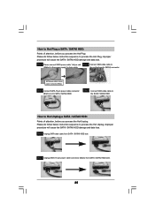
... Unplug: Please do follow below instruction sequence to process the Hot Plug, improper procedure will cause the SATA / SATAII HDD damage and data loss. the motherboard's SATAII connector.
... Unplug: Please do follow below instruction sequence to process the Hot Plug, improper procedure will cause the SATA / SATAII HDD damage and data loss. the motherboard's SATAII connector.
User Manual
Page 28
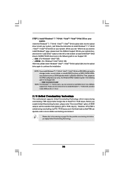
...OS on your system. NVIDIA® RAID drivers are in the Support CD: .. \ RAID Installation Guide NOTE. Then, please set the selection from ASRock support CD. For Windows® 7 / 7 64-bit users, you do you want to manage (create, convert, delete, or rebuild) RAID ...Technology. 28 Please use the native driver to install Windows® 7 / 7 64-bit OS, and then install ASRock All-in-1 driver. 2 . 1 5 Untied Overclocking Technology This motherboard supports Untied Overclocking Technology, which means during overclocking, but PCI / PCIE buses are in the following path in the ...
...OS on your system. NVIDIA® RAID drivers are in the Support CD: .. \ RAID Installation Guide NOTE. Then, please set the selection from ASRock support CD. For Windows® 7 / 7 64-bit users, you do you want to manage (create, convert, delete, or rebuild) RAID ...Technology. 28 Please use the native driver to install Windows® 7 / 7 64-bit OS, and then install ASRock All-in-1 driver. 2 . 1 5 Untied Overclocking Technology This motherboard supports Untied Overclocking Technology, which means during overclocking, but PCI / PCIE buses are in the following path in the ...
User Manual
Page 29
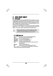
... press to enter the BIOS SETUP UTILITY after POST, restart the system by pressing + + , or by turning the system off and then back on the motherboard stores the BIOS SETUP UTILITY. BIOS SETUP UTILITY 3.1 Introduction This section explains how to use the BIOS SETUP UTILITY to enter the BIOS SETUP UTILITY...
... press to enter the BIOS SETUP UTILITY after POST, restart the system by pressing + + , or by turning the system off and then back on the motherboard stores the BIOS SETUP UTILITY. BIOS SETUP UTILITY 3.1 Introduction This section explains how to use the BIOS SETUP UTILITY to enter the BIOS SETUP UTILITY...

