User Manual
Page 5
.../support/index.asp 1.1 Package Contents One ASRock N68-GS / N68-S Motherboard (Micro ATX Form Factor: 9.6-in x 7.0-in, 24.4 cm x 17.8 cm) One ASRock N68-GS / N68-S Quick Installation Guide Two ASRock N68-GS / N68-S Support CD One 80-conductor Ultra ATA 66/100/133 IDE Ribbon Cable (Optional) One Serial ATA (SATA) Data Cable (Optional) One Serial ATA (SATA) ...
.../support/index.asp 1.1 Package Contents One ASRock N68-GS / N68-S Motherboard (Micro ATX Form Factor: 9.6-in x 7.0-in, 24.4 cm x 17.8 cm) One ASRock N68-GS / N68-S Quick Installation Guide Two ASRock N68-GS / N68-S Support CD One 80-conductor Ultra ATA 66/100/133 IDE Ribbon Cable (Optional) One Serial ATA (SATA) Data Cable (Optional) One Serial ATA (SATA) ...
User Manual
Page 11
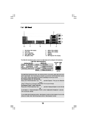
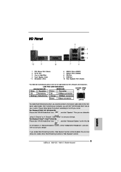
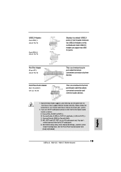
... 3 Line In (Light Blue) 4 Front Speaker (Lime) * 5 Microphone (Pink) 7 6 6 USB 2.0 Ports (USB01) 7 USB 2.0 Ports (USB23) 8 VGA Port 9 COM Port 10 PS/2 Keyboard Port (Purple) * For N68-GS motherboard, please refer to save your system. Click "Power" to the table below instructions according to select "2 Channel" or "4 Channel". For Windows® VistaTM / VistaTM 64...
... 3 Line In (Light Blue) 4 Front Speaker (Lime) * 5 Microphone (Pink) 7 6 6 USB 2.0 Ports (USB01) 7 USB 2.0 Ports (USB23) 8 VGA Port 9 COM Port 10 PS/2 Keyboard Port (Purple) * For N68-GS motherboard, please refer to save your system. Click "Power" to the table below instructions according to select "2 Channel" or "4 Channel". For Windows® VistaTM / VistaTM 64...
User Manual
Page 14
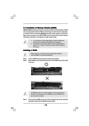
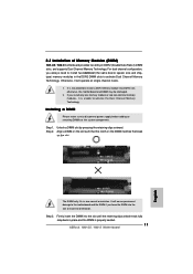
...install only one correct orientation. Unlock a DIMM slot by pressing the retaining clips outward. 2.3 Installation of Memory Modules (DIMM) N68-GS / N68-S motherboard provides two 240-pin DDR2 (Double Data Rate 2) DIMM slots, and supports Dual Channel Memory Technology. Firmly insert the DIMM into... the slot until the retaining clips at incorrect orientation. otherwise, this motherboard and DIMM may be damaged. 2. Align a DIMM on the slot such that the notch on the DIMM matches the break on the ...
...install only one correct orientation. Unlock a DIMM slot by pressing the retaining clips outward. 2.3 Installation of Memory Modules (DIMM) N68-GS / N68-S motherboard provides two 240-pin DDR2 (Double Data Rate 2) DIMM slots, and supports Dual Channel Memory Technology. Firmly insert the DIMM into... the slot until the retaining clips at incorrect orientation. otherwise, this motherboard and DIMM may be damaged. 2. Align a DIMM on the slot such that the notch on the DIMM matches the break on the ...
Quick Installation Guide
Page 1
...of merchantability or fitness for a particular purpose. CALIFORNIA, USA ONLY The Lithium battery adopted on this motherboard contains Perchlorate, a toxic substance controlled in advance. When you discard the Lithium battery in California, ...Perchlorate Best Management Practices (BMP) regulations passed by the purchaser for backup purpose, without written consent of ASRock Inc. Disclaimer: Specifications and information contained in this guide. Operation is subject to the following two conditions... of the FCC Rules. All rights reserved. 1 ASRock N68-GS / N68-S Motherboard English
...of merchantability or fitness for a particular purpose. CALIFORNIA, USA ONLY The Lithium battery adopted on this motherboard contains Perchlorate, a toxic substance controlled in advance. When you discard the Lithium battery in California, ...Perchlorate Best Management Practices (BMP) regulations passed by the purchaser for backup purpose, without written consent of ASRock Inc. Disclaimer: Specifications and information contained in this guide. Operation is subject to the following two conditions... of the FCC Rules. All rights reserved. 1 ASRock N68-GS / N68-S Motherboard English

Quick Installation Guide
Page 2
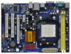
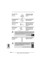
Motherboard Layout English 1 PS2_USB_PW1 Jumper 2 CPU Fan Connector (CPU_FAN1) 3 2 x 240-pin DDR2 DIMM Slots (Dual Channel: DDRII_1, DDRII_2; Yellow) 4 ATX Power Connector (ATXPWR1) 5 SATAII Connector (SATAII_2 (... Slot (PCIE2) 23 PCI Express x1 Slot (PCIE1) 24 ATX 12V Power Connector (ATX12V1) 25 CPU Heatsink Retention Module 26 AM2 940-Pin CPU Socket 2 ASRock N68-GS / N68-S Motherboard
Motherboard Layout English 1 PS2_USB_PW1 Jumper 2 CPU Fan Connector (CPU_FAN1) 3 2 x 240-pin DDR2 DIMM Slots (Dual Channel: DDRII_1, DDRII_2; Yellow) 4 ATX Power Connector (ATXPWR1) 5 SATAII Connector (SATAII_2 (... Slot (PCIE2) 23 PCI Express x1 Slot (PCIE1) 24 ATX 12V Power Connector (ATX12V1) 25 CPU Heatsink Retention Module 26 AM2 940-Pin CPU Socket 2 ASRock N68-GS / N68-S Motherboard
Quick Installation Guide
Page 3
... can only choose to the OS you are allowed to the table below instructions according to enable either Multi-Streaming function or Side Speaker function. 3 ASRock N68-GS / N68-S Motherboard English Please follow below for the LAN port LED indications. In "Advanced Options" screen, select "Independent Headphone", and click "OK" to the front panel audio...
... can only choose to the OS you are allowed to the table below instructions according to enable either Multi-Streaming function or Side Speaker function. 3 ASRock N68-GS / N68-S Motherboard English Please follow below for the LAN port LED indications. In "Advanced Options" screen, select "Independent Headphone", and click "OK" to the front panel audio...
Quick Installation Guide
Page 4
... any modifications of this manual, chapter 1 and 2 contain introduction of the Support CD. www.asrock.com/support/index.asp 1.1 Package Contents One ASRock N68-GS / N68-S Motherboard (Micro ATX Form Factor: 9.6-in x 7.0-in, 24.4 cm x 17.8 cm) One ASRock N68-GS / N68-S Quick Installation Guide Two ASRock N68-GS / N68-S Support CD One 80-conductor Ultra ATA 66/100/133 IDE Ribbon Cable (Optional...
... any modifications of this manual, chapter 1 and 2 contain introduction of the Support CD. www.asrock.com/support/index.asp 1.1 Package Contents One ASRock N68-GS / N68-S Motherboard (Micro ATX Form Factor: 9.6-in x 7.0-in, 24.4 cm x 17.8 cm) One ASRock N68-GS / N68-S Quick Installation Guide Two ASRock N68-GS / N68-S Support CD One 80-conductor Ultra ATA 66/100/133 IDE Ribbon Cable (Optional...

Quick Installation Guide
Page 5
...8GB (see CAUTION 2) - Max. Supports AMD's Cool 'n' QuietTM Technology - Integrated NVIDIA® GeForce 7025 graphics - DX9.0 VGA, Pixel Shader 3.0 - N68-S Realtek PHY RTL8201EL / 8201CL, speed 10/100 Mb/s - FSB 1000 MHz (2.0 GT/s) - Dual Channel DDR2 Memory Technology (see CAUTION 6) - 5.1 ...Athlon II X4 / X3 / X2 processors - Micro ATX Form Factor: 9.6-in x 7.0-in / Front Speaker / Microphone English 5 ASRock N68-GS / N68-S Motherboard N68-GS Realtek Giga PHY RTL8211CL, speed 10/100/1000 Mb/s - NVIDIA® GeForce 7025 / nForce 630a - 1.2 Specifications Platform CPU Chipset ...
...8GB (see CAUTION 2) - Max. Supports AMD's Cool 'n' QuietTM Technology - Integrated NVIDIA® GeForce 7025 graphics - DX9.0 VGA, Pixel Shader 3.0 - N68-S Realtek PHY RTL8201EL / 8201CL, speed 10/100 Mb/s - FSB 1000 MHz (2.0 GT/s) - Dual Channel DDR2 Memory Technology (see CAUTION 6) - 5.1 ...Athlon II X4 / X3 / X2 processors - Micro ATX Form Factor: 9.6-in x 7.0-in / Front Speaker / Microphone English 5 ASRock N68-GS / N68-S Motherboard N68-GS Realtek Giga PHY RTL8211CL, speed 10/100/1000 Mb/s - NVIDIA® GeForce 7025 / nForce 630a - 1.2 Specifications Platform CPU Chipset ...
Quick Installation Guide
Page 6
... +5V, +3.3V, Vcore OS - FCC, CE * For detailed product information, please visit our website: http://www.asrock.com 6 ASRock N68-GS / N68-S Motherboard SMBIOS 2.3.1 Support - Hybrid Booster: - ASRock AM2 Boost: ASRock Patented Technology to boost memory performance up to 12.5% (see CAUTION 7) - 1 x ATA133 IDE connector (supports 2 ... 24 pin ATX power connector - 4 pin 12V power connector - ACPI 1.1 Compliance Wake Up Events - Supports jumperfree - ASRock U-COP (see CAUTION 10) - AMI Legal BIOS - CPU Fan Tachometer - Intelligent Energy Saver (see CAUTION 13) -...
... +5V, +3.3V, Vcore OS - FCC, CE * For detailed product information, please visit our website: http://www.asrock.com 6 ASRock N68-GS / N68-S Motherboard SMBIOS 2.3.1 Support - Hybrid Booster: - ASRock AM2 Boost: ASRock Patented Technology to boost memory performance up to 12.5% (see CAUTION 7) - 1 x ATA133 IDE connector (supports 2 ... 24 pin ATX power connector - 4 pin 12V power connector - ACPI 1.1 Compliance Wake Up Events - Supports jumperfree - ASRock U-COP (see CAUTION 10) - AMI Legal BIOS - CPU Fan Tachometer - Intelligent Energy Saver (see CAUTION 13) -...
Quick Installation Guide
Page 7
... disk drive to SATAII mode. Please visit our website for CPU support list. This motherboard supports CPU up to SATAII connector directly. 8. It is a user-friendly ASRock overclocking tool which allows you adopt. Please refer to SATAII connector, please read "Untied...Untied Overclocking Technology, or using the third-party overclocking tools. We are not responsible for proper installation. 4. ASRock website: http://www.asrock.com 7 ASRock N68-GS / N68-S Motherboard English It should be less than 4GB for the reservation for the compatible memory modules. Before you want to ...
... disk drive to SATAII mode. Please visit our website for CPU support list. This motherboard supports CPU up to SATAII connector directly. 8. It is a user-friendly ASRock overclocking tool which allows you adopt. Please refer to SATAII connector, please read "Untied...Untied Overclocking Technology, or using the third-party overclocking tools. We are not responsible for proper installation. 4. ASRock website: http://www.asrock.com 7 ASRock N68-GS / N68-S Motherboard English It should be less than 4GB for the reservation for the compatible memory modules. Before you want to ...
Quick Installation Guide
Page 8
... the new BIOS file to your system is unstable after AM2 Boost function is able to access ASRock Instant Flash. If your system. The voltage regulator can update your system. 8 ASRock N68-GS / N68-S Motherboard English ASRock website: http://www.asrock.com 11. Before you resume the system, please check if the CPU fan on the AM2 CPU...
... the new BIOS file to your system is unstable after AM2 Boost function is able to access ASRock Instant Flash. If your system. The voltage regulator can update your system. 8 ASRock N68-GS / N68-S Motherboard English ASRock website: http://www.asrock.com 11. Before you resume the system, please check if the CPU fan on the AM2 CPU...
Quick Installation Guide
Page 9
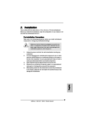
... do so may damage the motherboard. 9 ASRock N68-GS / N68-S Motherboard English When placing screws into it on the carpet or the like. Installation This is detached from the wall socket before touching any component. 2. To avoid damaging the motherboard components due to the motherboard, peripherals, and/or components....a grounded wrist strap or touch a safety grounded object before you handle components. 3. Pre-installation Precautions Take note of your motherboard directly on a grounded antistatic pad or in the bag that the power is switched off or the power cord is a Micro...
... do so may damage the motherboard. 9 ASRock N68-GS / N68-S Motherboard English When placing screws into it on the carpet or the like. Installation This is detached from the wall socket before touching any component. 2. To avoid damaging the motherboard components due to the motherboard, peripherals, and/or components....a grounded wrist strap or touch a safety grounded object before you handle components. 3. Pre-installation Precautions Take note of your motherboard directly on a grounded antistatic pad or in the bag that the power is switched off or the power cord is a Micro...
Quick Installation Guide
Page 10
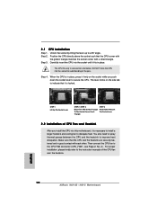
...CPU is in one correct orientation. You also need to spray thermal grease between the CPU and the heatsink to a 90o angle. English 10 ASRock N68-GS / N68-S Motherboard Unlock the socket by lifting the lever up to improve heat dissipation. Step 3. Make sure that the CPU and the heatsink are securely fastened... other. The CPU fits only in place, press it fits in good contact with a small triangle. DO NOT force the CPU into this motherboard, it is necessary to install a larger heatsink and cooling fan to avoid bending of the CPU fan and the heatsink. The lever clicks on...
...CPU is in one correct orientation. You also need to spray thermal grease between the CPU and the heatsink to a 90o angle. English 10 ASRock N68-GS / N68-S Motherboard Unlock the socket by lifting the lever up to improve heat dissipation. Step 3. Make sure that the CPU and the heatsink are securely fastened... other. The CPU fits only in place, press it fits in good contact with a small triangle. DO NOT force the CPU into this motherboard, it is necessary to install a larger heatsink and cooling fan to avoid bending of the CPU fan and the heatsink. The lever clicks on...
Quick Installation Guide
Page 11
...not allowed to activate the Dual Channel Memory Technology. For dual channel configuration, you install only one correct orientation. otherwise, this motherboard and DIMM may be damaged. 2. Step 2. If you always need to install two identical (the same brand, speed, size... is unable to install a DDR memory module into DDR2 slot; 2.3 Installation of Memory Modules (DIMM) N68-GS / N68-S motherboard provides two 240-pin DDR2 (Double Data Rate 2) DIMM slots, and supports Dual Channel Memory Technology. It is properly seated. 11 ASRock N68-GS / N68-S Motherboard Step 3.
...not allowed to activate the Dual Channel Memory Technology. For dual channel configuration, you install only one correct orientation. otherwise, this motherboard and DIMM may be damaged. 2. Step 2. If you always need to install two identical (the same brand, speed, size... is unable to install a DDR memory module into DDR2 slot; 2.3 Installation of Memory Modules (DIMM) N68-GS / N68-S motherboard provides two 240-pin DDR2 (Double Data Rate 2) DIMM slots, and supports Dual Channel Memory Technology. It is properly seated. 11 ASRock N68-GS / N68-S Motherboard Step 3.
Quick Installation Guide
Page 12
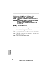
PCIE slots: PCIE1 (PCIE x1 slot) is completely seated on this motherboard. Align the card connector with x1 lane width cards, such as Gigabit LAN card, SATA2 card, etc. Keep the screws for PCI Express cards with ... graphics cards. PCIE2 (PCIE x16 slot) is unplugged. Before installing the expansion card, please make necessary hardware settings for PCI Express cards with screws. 12 ASRock N68-GS / N68-S Motherboard English Remove the bracket facing the slot that have the 32-bit PCI interface.
PCIE slots: PCIE1 (PCIE x1 slot) is completely seated on this motherboard. Align the card connector with x1 lane width cards, such as Gigabit LAN card, SATA2 card, etc. Keep the screws for PCI Express cards with ... graphics cards. PCIE2 (PCIE x16 slot) is unplugged. Before installing the expansion card, please make necessary hardware settings for PCI Express cards with screws. 12 ASRock N68-GS / N68-S Motherboard English Remove the bracket facing the slot that have the 32-bit PCI interface.
Quick Installation Guide
Page 13
... 5 seconds. When the jumper cap is placed on pins, the jumper is placed on these 2 pins. However, please do the clear-CMOS action. English 13 ASRock N68-GS / N68-S Motherboard Note: To select +5VSB, it down before you do not clear the CMOS right after you must boot up events. To clear and reset the...
... 5 seconds. When the jumper cap is placed on pins, the jumper is placed on these 2 pins. However, please do the clear-CMOS action. English 13 ASRock N68-GS / N68-S Motherboard Note: To select +5VSB, it down before you do not clear the CMOS right after you must boot up events. To clear and reset the...
Quick Installation Guide
Page 14
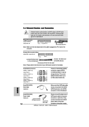
... these headers and connectors. The current SATAII interface allows up to the power connector of the connector. ASRock N68-GS / N68-S Motherboard English Serial ATA (SATA) Please connect the black end of the SATA data cable can be connected to ... 1.1): see p.2, No. 5) (SATAII_3 (PORT 2.0): see p.2, No. 8) (SATAII_4 (PORT 2.1): see p.2 No. 19) the red-striped side to the instruction of the motherboard! • Floppy Connector (33-pin FLOPPY1) (see p.2, No. 7) SATAII_3 SATAII_1 (PORT 2.0) (PORT 1.0) SATAII_4 SATAII_2 (PORT 2.1) (PORT 1.1) These four Serial ATAII (SATAII...
... these headers and connectors. The current SATAII interface allows up to the power connector of the connector. ASRock N68-GS / N68-S Motherboard English Serial ATA (SATA) Please connect the black end of the SATA data cable can be connected to ... 1.1): see p.2, No. 5) (SATAII_3 (PORT 2.0): see p.2, No. 8) (SATAII_4 (PORT 2.1): see p.2 No. 19) the red-striped side to the instruction of the motherboard! • Floppy Connector (33-pin FLOPPY1) (see p.2, No. 7) SATAII_3 SATAII_1 (PORT 2.0) (PORT 1.0) SATAII_4 SATAII_2 (PORT 2.1) (PORT 1.1) These four Serial ATAII (SATAII...
Quick Installation Guide
Page 15
... the Front Panel Control option from [Auto] to Ground (GND). Each USB 2.0 header can support two USB 2.0 ports. Connect Ground (GND) to [Enabled]. 15 ASRock N68-GS / N68-S Motherboard English D. Enter Advanced Settings, and then select Chipset Configuration. Please follow the instruction in our manual and chassis manual to MIC2_L. B. You don't need to ...
... the Front Panel Control option from [Auto] to Ground (GND). Each USB 2.0 header can support two USB 2.0 ports. Connect Ground (GND) to [Enabled]. 15 ASRock N68-GS / N68-S Motherboard English D. Enter Advanced Settings, and then select Chipset Configuration. Please follow the instruction in our manual and chassis manual to MIC2_L. B. You don't need to ...
Quick Installation Guide
Page 16
... No. 2) 4 3 2 1 Please connect the CPU fan cable to this connector and match the black wire to this connector. 1 13 Though this motherboard provides 24-pin ATX power connector, 12 24 it to this header. Pin 1-3 Connected 3-Pin Fan Installation ATX Power Connector (24-pin ATXPWR1) (see ...power supply, please plug your power supply along with Pin 1 and Pin 13. 20-Pin ATX Power Supply Installation 1 13 English 16 ASRock N68-GS / N68-S Motherboard System Panel Header (9-pin PANEL1) (see p.2 No. 12) Please connect a chassis fan cable to this connector and match the black wire...
... No. 2) 4 3 2 1 Please connect the CPU fan cable to this connector and match the black wire to this connector. 1 13 Though this motherboard provides 24-pin ATX power connector, 12 24 it to this header. Pin 1-3 Connected 3-Pin Fan Installation ATX Power Connector (24-pin ATXPWR1) (see ...power supply, please plug your power supply along with Pin 1 and Pin 13. 20-Pin ATX Power Supply Installation 1 13 English 16 ASRock N68-GS / N68-S Motherboard System Panel Header (9-pin PANEL1) (see p.2 No. 12) Please connect a chassis fan cable to this connector and match the black wire...
Quick Installation Guide
Page 17
...VistaTM or Windows® VistaTM 64-bit on your SATA / SATAII HDDs without RAID functions, you apply Untied Overclocking Technology. 17 ASRock N68-GS / N68-S Motherboard English Before you want to make a SATA / SATAII driver diskette. Please follow the order from [Auto] to [CPU, ... Please refer to the warning on page 7 for detailed procedures: ..\ RAID Installation Guide 2 . 1 0 Untied Overclocking Technology This motherboard supports Untied Overclocking Technology, which means during overclocking, FSB enjoys better margin due to change the BIOS setting. Therefore, the drivers you ...
...VistaTM or Windows® VistaTM 64-bit on your SATA / SATAII HDDs without RAID functions, you apply Untied Overclocking Technology. 17 ASRock N68-GS / N68-S Motherboard English Before you want to make a SATA / SATAII driver diskette. Please follow the order from [Auto] to [CPU, ... Please refer to the warning on page 7 for detailed procedures: ..\ RAID Installation Guide 2 . 1 0 Untied Overclocking Technology This motherboard supports Untied Overclocking Technology, which means during overclocking, FSB enjoys better margin due to change the BIOS setting. Therefore, the drivers you ...

