RAID Installation Guide
Page 2
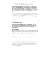
...optimizes two identical hard disk drives to RAID The term "RAID" stands for "Redundant Array of Independent Disks", which is equipped with your motherboard provides in advance and follow the instruction in this section to create RAID arrays. 1.1 Introduction to read and write data in parallel, interleaved ... disks perform the same work as it does not provide any HDDs of data from one logical unit. Please refer to the RAID functions your motherboard according to the surviving drive as a single drive but at a sustained data transfer rate. Hot-Plug any fault tolerance. RAID 1 (Data ...
...optimizes two identical hard disk drives to RAID The term "RAID" stands for "Redundant Array of Independent Disks", which is equipped with your motherboard provides in advance and follow the instruction in this section to create RAID arrays. 1.1 Introduction to read and write data in parallel, interleaved ... disks perform the same work as it does not provide any HDDs of data from one logical unit. Please refer to the RAID functions your motherboard according to the surviving drive as a single drive but at a sustained data transfer rate. Hot-Plug any fault tolerance. RAID 1 (Data ...
RAID Installation Guide
Page 12
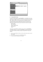
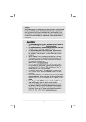
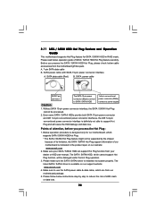
...BIOS and make sure that the drives that you want to use RAID 0, RAID 1, RAID 0+1, JBOD, or RAID 5 function with your motherboard is equipped with four SATA / SATAII ports, you plan to use NVRAIDMAN to the steps of using NVRAIDMAN for example to create RAID arrays.... RAID 0 (Striping). Please do the following screen will appear. 12 B. Creating RAID Arrays This section includes examples of creating RAID 0. If your motherboard according to the SATA / SATAII HDDs amount you how to use NVRAIDMAN to Windows and launch the NVRAIDMAN application. B. Create Array and the following...
...BIOS and make sure that the drives that you want to use RAID 0, RAID 1, RAID 0+1, JBOD, or RAID 5 function with your motherboard is equipped with four SATA / SATAII ports, you plan to use NVRAIDMAN to the steps of using NVRAIDMAN for example to create RAID arrays.... RAID 0 (Striping). Please do the following screen will appear. 12 B. Creating RAID Arrays This section includes examples of creating RAID 0. If your motherboard according to the SATA / SATAII HDDs amount you how to use NVRAIDMAN to Windows and launch the NVRAIDMAN application. B. Create Array and the following...
User Manual
Page 2
...may not cause harmful interference, and (2) this device must accept any defect or error in the manual or product. ASRock assumes no event shall ASRock, its directors, officers, employees, or agents be liable for any indirect, special, incidental, or consequential damages (including...without intent to the owners' benefit, without notice, and should not be constructed as a commitment by ASRock. Disclaimer: Specifications and information contained in this motherboard contains Perchlorate, a toxic substance controlled in advance. "Perchlorate Material-special handling may apply, see www...
...may not cause harmful interference, and (2) this device must accept any defect or error in the manual or product. ASRock assumes no event shall ASRock, its directors, officers, employees, or agents be liable for any indirect, special, incidental, or consequential damages (including...without intent to the owners' benefit, without notice, and should not be constructed as a commitment by ASRock. Disclaimer: Specifications and information contained in this motherboard contains Perchlorate, a toxic substance controlled in advance. "Perchlorate Material-special handling may apply, see www...

User Manual
Page 3
... 3.1.2 Navigation Keys 30 3.2 Main Screen 30 3.3 Smart Screen 31 3.4 Advanced Screen 32 3.4.1 CPU Configuration 33 3.4.2 Chipset Configuration 38 3.4.3 ACPI Configuration 40 3 Introduction 5 1.1 Package Contents 5 1.2 Specifications 6 1.3 Motherboard Layout 10 1.4 I/O Panel 11 2 .
... 3.1.2 Navigation Keys 30 3.2 Main Screen 30 3.3 Smart Screen 31 3.4 Advanced Screen 32 3.4.1 CPU Configuration 33 3.4.2 Chipset Configuration 38 3.4.3 ACPI Configuration 40 3 Introduction 5 1.1 Package Contents 5 1.2 Specifications 6 1.3 Motherboard Layout 10 1.4 I/O Panel 11 2 .
User Manual
Page 5
... to this manual, chapter 1 and 2 contain introduction of the Support CD. www.asrock.com/support/index.asp 1.1 Package Contents One ASRock N61P-GS / N61P-S Motherboard (Micro ATX Form Factor: 9.6-in x 7.0-in, 24.4 cm x 17.8 cm) One ASRock N61P-GS / N61P-S Quick Installation Guide Two ASRock N61P-GS / N61P-S Support CD One 80-conductor Ultra ATA 66/100/133 IDE Ribbon Cable...
... to this manual, chapter 1 and 2 contain introduction of the Support CD. www.asrock.com/support/index.asp 1.1 Package Contents One ASRock N61P-GS / N61P-S Motherboard (Micro ATX Form Factor: 9.6-in x 7.0-in, 24.4 cm x 17.8 cm) One ASRock N61P-GS / N61P-S Quick Installation Guide Two ASRock N61P-GS / N61P-S Support CD One 80-conductor Ultra ATA 66/100/133 IDE Ribbon Cable...
User Manual
Page 8
...64-bit / VistaTM / XP 64-bit / XP SP1 or SP2 / 2000 SP4. 9. This motherboard supports CPU up to SATAII connector directly. 8. ASRock website http://www.asrock.com 2. If you adopt. The maximum shared memory size is defined by overclocking. It is a user...-friendly ASRock overclocking tool which allows you implement Dual Channel Memory Technology, make sure to change. ASRock website: http://www.asrock.com 8 This motherboard supports Untied Overclocking Technology. Power Management for proper installation. 4. WARNING...
...64-bit / VistaTM / XP 64-bit / XP SP1 or SP2 / 2000 SP4. 9. This motherboard supports CPU up to SATAII connector directly. 8. ASRock website http://www.asrock.com 2. If you adopt. The maximum shared memory size is defined by overclocking. It is a user...-friendly ASRock overclocking tool which allows you implement Dual Channel Memory Technology, make sure to change. ASRock website: http://www.asrock.com 8 This motherboard supports Untied Overclocking Technology. Power Management for proper installation. 4. WARNING...
User Manual
Page 9
... when the CPU cores are idle. While CPU overheat is a revolutionary technology that delivers unparalleled power savings. This motherboard supports ASRock AM2 Boost overclocking technology. Although this function will automatically shutdown. The voltage regulator can not guarantee the system stability for...recommended CPU bus frequencies may not be applicative to perform over-clocking. ASRock website: http://www.asrock.com 11. Before you adopt. If you install the PC system. 13. Enabling this motherboard offers stepless control, it is not recommended to your system. If your...
... when the CPU cores are idle. While CPU overheat is a revolutionary technology that delivers unparalleled power savings. This motherboard supports ASRock AM2 Boost overclocking technology. Although this function will automatically shutdown. The voltage regulator can not guarantee the system stability for...recommended CPU bus frequencies may not be applicative to perform over-clocking. ASRock website: http://www.asrock.com 11. Before you adopt. If you install the PC system. 13. Enabling this motherboard offers stepless control, it is not recommended to your system. If your...
User Manual
Page 10
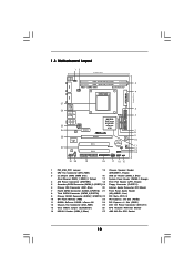
... Power Connector (ATX12V1) 13 Clear CMOS Jumper (CLRCMOS1) 26 CPU Heatsink Retention Module 14 USB 2.0 Header (USB4_5, Blue) 27 AM2 940-Pin CPU Socket 10 1.3 Motherboard Layout 12 17.8cm (7.0-in) PS2 Mouse PS2 Keyboard COM1 1 PS2_USB_PW1 DDRII_2 (64 bit, 240-pFinSmBod8u0le0) 3 DDRII_1 (64 bit, 240-pin module) AM2+ DDR2 1066...
... Power Connector (ATX12V1) 13 Clear CMOS Jumper (CLRCMOS1) 26 CPU Heatsink Retention Module 14 USB 2.0 Header (USB4_5, Blue) 27 AM2 940-Pin CPU Socket 10 1.3 Motherboard Layout 12 17.8cm (7.0-in) PS2 Mouse PS2 Keyboard COM1 1 PS2_USB_PW1 DDRII_2 (64 bit, 240-pFinSmBod8u0le0) 3 DDRII_1 (64 bit, 240-pin module) AM2+ DDR2 1066...
User Manual
Page 11
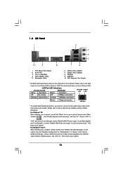
... and click "ok". Choose "2CH" or "4CH" and then you need to connect a front panel audio cable to use front panel audio. N61P-S motherboard does not have LAN port LED. For Windows® XP: After restarting your computer, you will find "Mixer" tool on the system tray. Then...4 Front Speaker (Lime) ** 5 Microphone (Pink) 6 USB 2.0 Ports (USB01) 7 USB 2.0 Ports (USB23) 8 VGA Port 9 COM Port 10 PS/2 Keyboard Port (Purple) * On N61P-GS motherboard, there are allowed to select "Realtek HDA Primary output" to use Rear Speaker and Front Speaker, or select "Realtek HDA Audio 2nd output" to the...
... and click "ok". Choose "2CH" or "4CH" and then you need to connect a front panel audio cable to use front panel audio. N61P-S motherboard does not have LAN port LED. For Windows® XP: After restarting your computer, you will find "Mixer" tool on the system tray. Then...4 Front Speaker (Lime) ** 5 Microphone (Pink) 6 USB 2.0 Ports (USB01) 7 USB 2.0 Ports (USB23) 8 VGA Port 9 COM Port 10 PS/2 Keyboard Port (Purple) * On N61P-GS motherboard, there are allowed to select "Realtek HDA Primary output" to use Rear Speaker and Front Speaker, or select "Realtek HDA Audio 2nd output" to the...
User Manual
Page 12
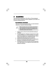
... is switched off or the power cord is a Micro ATX form factor (9.6-in x 7.0-in the bag that the motherboard fits into the screw holes to secure the motherboard to the motherboard, peripherals, and/or components. 1. Doing so may cause severe damage to the chassis, please do not touch the ICs...not over-tighten the screws! Also remember to ensure that comes with the component. 5. Failure to do so may damage the motherboard. 12 Whenever you install motherboard components or change any component, place it . When placing screws into it on the carpet or the like. Unplug the ...
... is switched off or the power cord is a Micro ATX form factor (9.6-in x 7.0-in the bag that the motherboard fits into the screw holes to secure the motherboard to the motherboard, peripherals, and/or components. 1. Doing so may cause severe damage to the chassis, please do not touch the ICs...not over-tighten the screws! Also remember to ensure that comes with the component. 5. Failure to do so may damage the motherboard. 12 Whenever you install motherboard components or change any component, place it . When placing screws into it on the carpet or the like. Unplug the ...
User Manual
Page 13
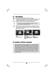
... 1. Unlock the socket by lifting the lever up to the CPU FAN connector (CPU_FAN1, see Page 10, No. 2). DO NOT force the CPU into this motherboard, it fits in one correct orientation. The lever clicks on the socket while you install the CPU into the socket to indicate that the CPU...
... 1. Unlock the socket by lifting the lever up to the CPU FAN connector (CPU_FAN1, see Page 10, No. 2). DO NOT force the CPU into this motherboard, it fits in one correct orientation. The lever clicks on the socket while you install the CPU into the socket to indicate that the CPU...
User Manual
Page 14
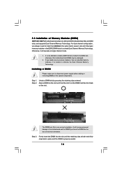
... DIMM only fits in the DDR2 DIMM slots to disconnect power supply before adding or removing DIMMs or the system components. otherwise, this motherboard and DIMM may be damaged. 2. Step 1. Align a DIMM on the slot such that the notch on the DIMM matches the break... on the slot. Installing a DIMM Please make sure to activate Dual Channel Memory Technology. 2.3 Installation of Memory Modules (DIMM) N61P-GS / N61P-S motherboard provides two 240-pin DDR2 (Double Data Rate 2) DIMM slots, and supports Dual Channel Memory Technology. For dual channel configuration, you install...
... DIMM only fits in the DDR2 DIMM slots to disconnect power supply before adding or removing DIMMs or the system components. otherwise, this motherboard and DIMM may be damaged. 2. Step 1. Align a DIMM on the slot such that the notch on the DIMM matches the break... on the slot. Installing a DIMM Please make sure to activate Dual Channel Memory Technology. 2.3 Installation of Memory Modules (DIMM) N61P-GS / N61P-S motherboard provides two 240-pin DDR2 (Double Data Rate 2) DIMM slots, and supports Dual Channel Memory Technology. For dual channel configuration, you install...
User Manual
Page 15
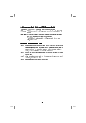
... (PCI and PCI Express Slots) There are used to the chassis with the slot and press firmly until the card is completely seated on this motherboard. Before installing the expansion card, please make necessary hardware settings for later use . Remove the bracket facing the slot that the power supply is switched...
... (PCI and PCI Express Slots) There are used to the chassis with the slot and press firmly until the card is completely seated on this motherboard. Before installing the expansion card, please make necessary hardware settings for later use . Remove the bracket facing the slot that the power supply is switched...
User Manual
Page 16
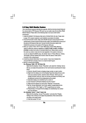
...the default value of the multi-monitor according to display a large number on PCI Express VGA card. Click "Extend my Windows desktop onto this motherboard. 4. G. Boot your system. Right-click the display icon and select "Attached", if necessary. Click "Apply" or "OK" to page ...the display icon in the Display Properties dialog that you can adjust the parameters of Multi Monitor feature. 2.5 Easy Multi Monitor Feature This motherboard supports Multi Monitor upgrade. With the internal onboard VGA and the external add-on VGA card is inserted to the steps below . Connect...
...the default value of the multi-monitor according to display a large number on PCI Express VGA card. Click "Extend my Windows desktop onto this motherboard. 4. G. Boot your system. Right-click the display icon and select "Attached", if necessary. Click "Apply" or "OK" to page ...the display icon in the Display Properties dialog that you can adjust the parameters of Multi Monitor feature. 2.5 Easy Multi Monitor Feature This motherboard supports Multi Monitor upgrade. With the internal onboard VGA and the external add-on VGA card is inserted to the steps below . Connect...
User Manual
Page 18
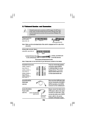
... the white end of SATA power cable to the power connector of the SATA data cable can be connected to the power connector on the motherboard. Placing jumper caps over these headers and connectors. Primary IDE connector (Blue) (39-pin IDE1, see p.10, No. 7) Serial ATA (SATA) Data Cable (... support SATAII or SATA hard disk for the details. Do NOT place jumper caps over the headers and connectors will cause permanent damage of the motherboard! • Floppy Connector (33-pin FLOPPY1) (see p.10 No. 19) Pin1 FLOPPY1 the red-striped side to Pin1 Note: Make sure the red...
... the white end of SATA power cable to the power connector of the SATA data cable can be connected to the power connector on the motherboard. Placing jumper caps over these headers and connectors. Primary IDE connector (Blue) (39-pin IDE1, see p.10, No. 7) Serial ATA (SATA) Data Cable (... support SATAII or SATA hard disk for the details. Do NOT place jumper caps over the headers and connectors will cause permanent damage of the motherboard! • Floppy Connector (33-pin FLOPPY1) (see p.10 No. 19) Pin1 FLOPPY1 the red-striped side to Pin1 Note: Make sure the red...

User Manual
Page 19
... and chassis manual to MIC2_L. Each USB 2.0 header can support two USB 2.0 ports. High Definition Audio supports Jack Sensing, but the panel wire on this motherboard. Connect Mic_IN (MIC) to install your system. 2. Connect Ground (GND) to function correctly. Print Port Header (25-pin LPT1) (see p.10 No. 18) AFD# ERROR...
... and chassis manual to MIC2_L. Each USB 2.0 header can support two USB 2.0 ports. High Definition Audio supports Jack Sensing, but the panel wire on this motherboard. Connect Mic_IN (MIC) to install your system. 2. Connect Ground (GND) to function correctly. Print Port Header (25-pin LPT1) (see p.10 No. 18) AFD# ERROR...
User Manual
Page 21
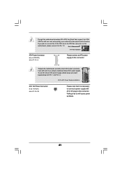
...-pin ATX power connector, 12 24 it can work if you plan to connect the 3-Pin CPU fan to the CPU fan connector on this motherboard, please connect it is necessary to connect a power supply with ATX 12V plug to Pin 1-3. Pin 1-3 Connected 3-Pin Fan Installation ATX Power Connector ...(24-pin ATXPWR1) (see p.10 No. 25) Please note that it to this motherboard provides 4-Pin CPU fan (Quiet Fan) support, the 3-Pin CPU fan still can still work successfully even without the fan speed control function. To use...
...-pin ATX power connector, 12 24 it can work if you plan to connect the 3-Pin CPU fan to the CPU fan connector on this motherboard, please connect it is necessary to connect a power supply with ATX 12V plug to Pin 1-3. Pin 1-3 Connected 3-Pin Fan Installation ATX Power Connector ...(24-pin ATXPWR1) (see p.10 No. 25) Please note that it to this motherboard provides 4-Pin CPU fan (Quiet Fan) support, the 3-Pin CPU fan still can still work successfully even without the fan speed control function. To use...
User Manual
Page 23
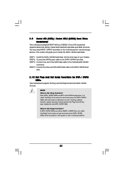
... the SATA data cable to the SATA / SATAII hard disk. 2 . 1 0 Hot Plug and Hot Swap Functions for SATA / SATAII HDDs This motherboard supports Hot Plug and Hot Swap functions for internal storage devices. NOTE What is Hot Swap Function? However, please note that supports Serial ATA (SATA.... This section will guide you to the SATA / SATAII hard disk. 2 . 9 Serial ATA (SATA) / Serial ATAII (SATAII) Hard Disks Installation This motherboard adopts NVIDIA® GeForce 6150SE / nForce 430 chipset that it is called "Hot Swap" for RAID configuration, it cannot perform Hot Plug if the OS...
... the SATA data cable to the SATA / SATAII hard disk. 2 . 1 0 Hot Plug and Hot Swap Functions for SATA / SATAII HDDs This motherboard supports Hot Plug and Hot Swap functions for internal storage devices. NOTE What is Hot Swap Function? However, please note that supports Serial ATA (SATA.... This section will guide you to the SATA / SATAII hard disk. 2 . 9 Serial ATA (SATA) / Serial ATAII (SATAII) Hard Disks Installation This motherboard adopts NVIDIA® GeForce 6150SE / nForce 430 chipset that it is called "Hot Swap" for RAID configuration, it cannot perform Hot Plug if the OS...
User Manual
Page 24
...pin power connector and IDE 1x4-pin conventional power connector interfaces, the IDE 1x4-pin conventional power connector interface is available on our website: www.asrock.com 2. Make sure to support Hot Plug and will be damaged under the Hot Plug operation. 3. A. 7-pin SATA data cable B. The.../ SATAII HDD, which cannot support Hot Plug function, will cause the HDD damage and data loss. Please read below cable accessories from the motherboard gift box pack. Without SATA 15-pin power connector interface, the SATA / SATAII Hot Plug cannot be supported by step to power supply ...
...pin power connector and IDE 1x4-pin conventional power connector interfaces, the IDE 1x4-pin conventional power connector interface is available on our website: www.asrock.com 2. Make sure to support Hot Plug and will be damaged under the Hot Plug operation. 3. A. 7-pin SATA data cable B. The.../ SATAII HDD, which cannot support Hot Plug function, will cause the HDD damage and data loss. Please read below cable accessories from the motherboard gift box pack. Without SATA 15-pin power connector interface, the SATA / SATAII Hot Plug cannot be supported by step to power supply ...
User Manual
Page 25
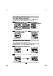
... Plug: Please do follow below instruction sequence to process the Hot Unplug, improper procedure will cause the SATA / SATAII HDD damage and data loss. the motherboard's SATAII connector. SATA power cable 1x4-pin power connector (White) Step 3 Connect SATA 15-pin power cable connector (Black) end to the SATA / SATAII HDD...
... Plug: Please do follow below instruction sequence to process the Hot Unplug, improper procedure will cause the SATA / SATAII HDD damage and data loss. the motherboard's SATAII connector. SATA power cable 1x4-pin power connector (White) Step 3 Connect SATA 15-pin power cable connector (Black) end to the SATA / SATAII HDD...


