
User Manual
Page 3
Installation 13 Pre-installation Precautions 13 2.1 CPU Installation 14 2.2 Installation of CPU Fan and Heatsink 14 2.3 Installation of Memory Modules (DIMM 15 2.4 Expansion Slots (PCI and PCI Express Slots 17 2.5 ATITM CrossFireXTM and Quad CrossFireXTM Operation Guide . 18 2.6 Surround Display Feature 21 2.7 Jumpers Setup 22 2.8 Onboard Headers and Connectors 23 2.9 HDMI_SPDIF Header ...
Installation 13 Pre-installation Precautions 13 2.1 CPU Installation 14 2.2 Installation of CPU Fan and Heatsink 14 2.3 Installation of Memory Modules (DIMM 15 2.4 Expansion Slots (PCI and PCI Express Slots 17 2.5 ATITM CrossFireXTM and Quad CrossFireXTM Operation Guide . 18 2.6 Surround Display Feature 21 2.7 Jumpers Setup 22 2.8 Onboard Headers and Connectors 23 2.9 HDMI_SPDIF Header ...

User Manual
Page 6
... 2.0 x16 slots (green @ x16 mode, orange @ x4 mode) - 1 x PCI Express 2.0 x1 slot - 3 x PCI slots - Northbridge: AMD 770 - Max. capacity of system memory: 16GB (see CAUTION 1) - Supports Wake-On-LAN I /O - Support for Socket AM3 processors: AMD PhenomTM II X4 / ...
... 2.0 x16 slots (green @ x16 mode, orange @ x4 mode) - 1 x PCI Express 2.0 x1 slot - 3 x PCI slots - Northbridge: AMD 770 - Max. capacity of system memory: 16GB (see CAUTION 1) - Supports Wake-On-LAN I /O - Support for Socket AM3 processors: AMD PhenomTM II X4 / ...

User Manual
Page 17
...Gigabit LAN card, SATA2 card, etc., or used to install PCI Express graphics cards to support CrossFireXTM function. 1. If you start the installation. PCIE2 (PCIE x16 slot; Step 6. PCI Slots: PCI slots are 3 PCI slots and 3 PCI Express slots on this motherboard, please install it on page 18.... 2.4 Expansion Slots (PCI and PCI Express Slots) There are used to install expansion cards that have the 32-bit PCI interface. PCIE Slots: PCIE1 (...
...Gigabit LAN card, SATA2 card, etc., or used to install PCI Express graphics cards to support CrossFireXTM function. 1. If you start the installation. PCIE2 (PCIE x16 slot; Step 6. PCI Slots: PCI slots are 3 PCI slots and 3 PCI Express slots on this motherboard, please install it on page 18.... 2.4 Expansion Slots (PCI and PCI Express Slots) There are used to install expansion cards that have the 32-bit PCI interface. PCIE Slots: PCIE1 (...

User Manual
Page 21
... ATITM CrossFireXTM technology, please check AMD website for updates and details. 2.6 Surround Display Feature This motherboard supports Surround Display upgrade. With the external add-on PCI Express VGA cards, you can freely enjoy the benefit of CrossFireXTM and Quad CrossFireXTM feature. * CrossFireXTM appearing here is a registered trademark of ATITM Technologies Inc...
... ATITM CrossFireXTM technology, please check AMD website for updates and details. 2.6 Surround Display Feature This motherboard supports Surround Display upgrade. With the external add-on PCI Express VGA cards, you can freely enjoy the benefit of CrossFireXTM and Quad CrossFireXTM feature. * CrossFireXTM appearing here is a registered trademark of ATITM Technologies Inc...

User Manual
Page 28
... pin definition of the HDMI VGA card you install. Step 3. For example, this motherboard. Step 4. Please refer to the user manual of PCI Express VGA card. Incorrect connection may be damaged. Connect the white end (B or C) of HDMI_SPDIF cable to the HDMI_SPDIF connector of HDMI VGA..., please carefully follow the below steps. •Step 1. Step 5. Otherwise, the motherboard and the VGA card may cause permanent damage to the PCI Express Graphics slot on page 17. white end (2-pin) (B) white end (3-pin) (C) Please do not connect the white end of HDMI_SPDIF cable...
... pin definition of the HDMI VGA card you install. Step 3. For example, this motherboard. Step 4. Please refer to the user manual of PCI Express VGA card. Incorrect connection may be damaged. Connect the white end (B or C) of HDMI_SPDIF cable to the HDMI_SPDIF connector of HDMI VGA..., please carefully follow the below steps. •Step 1. Step 5. Otherwise, the motherboard and the VGA card may cause permanent damage to the PCI Express Graphics slot on page 17. white end (2-pin) (B) white end (3-pin) (C) Please do not connect the white end of HDMI_SPDIF cable...

User Manual
Page 36
...® VistaTM 64-bit optical disk into the optical drive to boot your system, and follow below steps. " page, please insert the ASRock Support CD into the optical drive again to install Windows® VistaTM / Windows® VistaTM 64-bit OS on your system. Using SATA...disk into your system. 2.17 Untied Overclocking Technology This motherboard supports Untied Overclocking Technology, which means during overclocking, but PCI / PCIE buses are two ASRock Support CD in the motherboard gift box pack, please choose the one for the possible overclocking risk before you enable Untied...
...® VistaTM 64-bit optical disk into the optical drive to boot your system, and follow below steps. " page, please insert the ASRock Support CD into the optical drive again to install Windows® VistaTM / Windows® VistaTM 64-bit OS on your system. Using SATA...disk into your system. 2.17 Untied Overclocking Technology This motherboard supports Untied Overclocking Technology, which means during overclocking, but PCI / PCIE buses are two ASRock Support CD in the motherboard gift box pack, please choose the one for the possible overclocking risk before you enable Untied...

User Manual
Page 47
...Audio feature. The default value of multiple video controllers. DRAM Voltage Use this feature is [Auto]. 47 The default value is [PCI]. 3.4.3 Chipset Configuration BIOS SETUP UTILITY Advanced Chipset Settings Onboard HD Audio Front Panel OnBoard Lan Primary Graphics Adapter DRAM Voltage [Auto] [Auto] [...Enabled] [PCI] [Auto] To set DRAM Voltage. +F1 F9 F10 ESC Select Screen Select Item Change Option General Help Load Defaults Save and Exit ...
...Audio feature. The default value of multiple video controllers. DRAM Voltage Use this feature is [Auto]. 47 The default value is [PCI]. 3.4.3 Chipset Configuration BIOS SETUP UTILITY Advanced Chipset Settings Onboard HD Audio Front Panel OnBoard Lan Primary Graphics Adapter DRAM Voltage [Auto] [Auto] [...Enabled] [PCI] [Auto] To set DRAM Voltage. +F1 F9 F10 ESC Select Screen Select Item Change Option General Help Load Defaults Save and Exit ...

User Manual
Page 48
... On Use this feature if the OS supports it. Suspend to RAM Use this item to power on AC / Power Loss Ring-In Power On PCI Devices Power On PS / 2 Keyboard Power On RTC Alarm Power On ACPI HPET Table [Disabled] [Disabled] [Power Off] [Disabled] [Disabled] [Disabled] [Disabled] [Disabled] Select auto...-2003, American Megatrends, Inc. If you to auto-detect or disable the Suspend-toRAM feature. The default value is [Disabled]. PCI Devices Power On Use this item to enable or disable PCI devices to turn on AC/Power Loss This allows you set this item to select whether to set the power...
... On Use this feature if the OS supports it. Suspend to RAM Use this item to power on AC / Power Loss Ring-In Power On PCI Devices Power On PS / 2 Keyboard Power On RTC Alarm Power On ACPI HPET Table [Disabled] [Disabled] [Power Off] [Disabled] [Disabled] [Disabled] [Disabled] [Disabled] Select auto...-2003, American Megatrends, Inc. If you to auto-detect or disable the Suspend-toRAM feature. The default value is [Disabled]. PCI Devices Power On Use this item to enable or disable PCI devices to turn on AC/Power Loss This allows you set this item to select whether to set the power...

User Manual
Page 51
...keep the default value unless the installed PCI expansion cards' specifications require other settings. PCI IDE BusMaster Use this section may cause the system to enable or disable the PCI IDE BusMaster feature. 51 Setting wrong values in units of PCI clocks for PCI device latency timer register. +F1 F9...Enabled]. 32Bit Data Transfer Use this item to maximize the IDE hard disk data transfer rate. 3.4.6 PCIPnP Configuration BIOS SETUP UTILITY Advanced Advanced PCI / PnP Settings PCI Latency Timer PCI IDE BusMaster [32] [Enabled] Value in this item to malfunction. S.M.A.R.T.
...keep the default value unless the installed PCI expansion cards' specifications require other settings. PCI IDE BusMaster Use this section may cause the system to enable or disable the PCI IDE BusMaster feature. 51 Setting wrong values in units of PCI clocks for PCI device latency timer register. +F1 F9...Enabled]. 32Bit Data Transfer Use this item to maximize the IDE hard disk data transfer rate. 3.4.6 PCIPnP Configuration BIOS SETUP UTILITY Advanced Advanced PCI / PnP Settings PCI Latency Timer PCI IDE BusMaster [32] [Enabled] Value in this item to malfunction. S.M.A.R.T.

Quick Installation Guide
Page 2
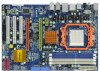
...) 34 Power Fan Connector (PWR_FAN1) 17 Secondary SATAII Connector (SATAII_2, Red) 35 Northbridge Controller 18 Chassis Fan Connector (CHA_FAN1) 2 ASRock M3A770DE Motherboard White) 27 Front Panel Audio Header 8 ATX Power Connector (ATXPWR1) (HD_AUDIO1, Lime) 9 Primary IDE Connector (IDE1, Blue)... (COM1) (Dual Channel B: DDR3_A2, DDR3_B2; Orange) 15 Fourth SATAII Connector (SATAII_4, Red) 32 PCI Express 2.0 x16 Slot (PCIE2; Green) 16 Chassis Speaker Header 33 PCI Express x1 Slot (PCIE1; Motherboard Layout English 1 PS2_USB_PW1 Jumper 19 USB 2.0 Header (USB8_9, Blue) ...
...) 34 Power Fan Connector (PWR_FAN1) 17 Secondary SATAII Connector (SATAII_2, Red) 35 Northbridge Controller 18 Chassis Fan Connector (CHA_FAN1) 2 ASRock M3A770DE Motherboard White) 27 Front Panel Audio Header 8 ATX Power Connector (ATXPWR1) (HD_AUDIO1, Lime) 9 Primary IDE Connector (IDE1, Blue)... (COM1) (Dual Channel B: DDR3_A2, DDR3_B2; Orange) 15 Fourth SATAII Connector (SATAII_4, Red) 32 PCI Express 2.0 x16 Slot (PCIE2; Green) 16 Chassis Speaker Header 33 PCI Express x1 Slot (PCIE1; Motherboard Layout English 1 PS2_USB_PW1 Jumper 19 USB 2.0 Header (USB8_9, Blue) ...

Quick Installation Guide
Page 6
...X2 processors - AMD LIVE!TM Ready - Support DDR3 1600/1333/1066/800 non-ECC, un-buffered memory (see CAUTION 5) 6 ASRock M3A770DE Motherboard English HD Audio Jack: Side Speaker/Rear Speaker/Central/Bass/ Line in , 30.5 cm x 20.8 cm - Supports Untied Overclocking Technology ...(see CAUTION 4) - 2 x PCI Express 2.0 x16 slots (green @ x16 mode, orange @ x4 mode) - 1 x PCI Express 2.0 x1 slot - 3 x PCI slots - Supports Wake-On-LAN I /O - ATX Form Factor: 12.0-in x 8.2-in /Front Speaker/Microphone (see CAUTION...
...X2 processors - AMD LIVE!TM Ready - Support DDR3 1600/1333/1066/800 non-ECC, un-buffered memory (see CAUTION 5) 6 ASRock M3A770DE Motherboard English HD Audio Jack: Side Speaker/Rear Speaker/Central/Bass/ Line in , 30.5 cm x 20.8 cm - Supports Untied Overclocking Technology ...(see CAUTION 4) - 2 x PCI Express 2.0 x16 slots (green @ x16 mode, orange @ x4 mode) - 1 x PCI Express 2.0 x1 slot - 3 x PCI slots - Supports Wake-On-LAN I /O - ATX Form Factor: 12.0-in x 8.2-in /Front Speaker/Microphone (see CAUTION...

Quick Installation Guide
Page 14
... the screws for PCI Express cards with screws. Green) is used for PCI Express x16 lane width graphics cards, or used to install PCI Express graphics cards to install only one PCI Express VGA card on this motherboard. Replace the system cover. 14 ASRock M3A770DE Motherboard English For ...as Gigabit LAN card, SATA2 card, etc., or used to install PCI Express graphics cards to "CrossFireXTM and Quad CrossFireXTM Operation Guide" on PCIE2 slot (Green). 2. PCI Slots: PCI slots are 3 PCI slots and 3 PCI Express slots on the slot. Please read the documentation of the compatible ...
... the screws for PCI Express cards with screws. Green) is used for PCI Express x16 lane width graphics cards, or used to install PCI Express graphics cards to install only one PCI Express VGA card on this motherboard. Replace the system cover. 14 ASRock M3A770DE Motherboard English For ...as Gigabit LAN card, SATA2 card, etc., or used to install PCI Express graphics cards to "CrossFireXTM and Quad CrossFireXTM Operation Guide" on PCIE2 slot (Green). 2. PCI Slots: PCI slots are 3 PCI slots and 3 PCI Express slots on the slot. Please read the documentation of the compatible ...

Quick Installation Guide
Page 18
... then set the option "Enable CrossFireTM" to infringe. * For further information of ATITM Technologies Inc., and is selected or not; With the external add-on PCI Express VGA cards, you have selected the option "Enable CrossFireTM", the CrossFireXTM function may not work actually. View CrossFireTM Enable CrossFireTM Although you can freely... "Yes". Your computer will automatically reboot. After restarting your computer, please confirm whether the option "Enable CrossFireTM" in the Support CD: ..\ Surround Display Information 18 ASRock M3A770DE Motherboard English Step 10.
... then set the option "Enable CrossFireTM" to infringe. * For further information of ATITM Technologies Inc., and is selected or not; With the external add-on PCI Express VGA cards, you have selected the option "Enable CrossFireTM", the CrossFireXTM function may not work actually. View CrossFireTM Enable CrossFireTM Although you can freely... "Yes". Your computer will automatically reboot. After restarting your computer, please confirm whether the option "Enable CrossFireTM" in the Support CD: ..\ Surround Display Information 18 ASRock M3A770DE Motherboard English Step 10.

Quick Installation Guide
Page 26
...] to the warning on page 8 for the possible overclocking risk before you apply Untied Overclocking Technology. 26 ASRock M3A770DE Motherboard English 2.12 Untied Overclocking Technology This motherboard supports Untied Overclocking Technology, which means during overclocking, but PCI / PCIE buses are in the fixed mode so that FSB can operate under a more stable overclocking...
...] to the warning on page 8 for the possible overclocking risk before you apply Untied Overclocking Technology. 26 ASRock M3A770DE Motherboard English 2.12 Untied Overclocking Technology This motherboard supports Untied Overclocking Technology, which means during overclocking, but PCI / PCIE buses are in the fixed mode so that FSB can operate under a more stable overclocking...
