RAID Installation Guide
Page 2
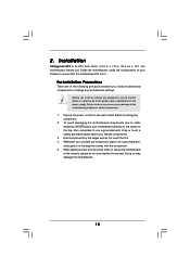
1. For SATA installation guide, please refer to SATA Hard Disks Installation 1.1 Serial ATA (SATA) Hard Disks Installation This motherboard adopts nVidia nForce3 chipset that supports Serial ATA (SATA) hard disks with RAID functions, including RAID 0, RAID 1, and JBOD. Guide to Serial ATA (SATA) Hard Disks Installation of "U ser Manual " in the support CD. This section will guide you how to create RAID on this motherboard for internal storage devices. You may install SATA hard disks on SATA ports. 2
1. For SATA installation guide, please refer to SATA Hard Disks Installation 1.1 Serial ATA (SATA) Hard Disks Installation This motherboard adopts nVidia nForce3 chipset that supports Serial ATA (SATA) hard disks with RAID functions, including RAID 0, RAID 1, and JBOD. Guide to Serial ATA (SATA) Hard Disks Installation of "U ser Manual " in the support CD. This section will guide you how to create RAID on this motherboard for internal storage devices. You may install SATA hard disks on SATA ports. 2
RAID Installation Guide
Page 4
... damage or data loss. 4 Guide to read and write data in parallel, interleaved stacks. This section will double the data transfer rate of RAID This motherboard adopts nVidia nForce3 chipset that optimizes two identical hard disk drives to RAID Configurations 2.1 Introduction of a single disk alone while the two hard disks perform...
... damage or data loss. 4 Guide to read and write data in parallel, interleaved stacks. This section will double the data transfer rate of RAID This motherboard adopts nVidia nForce3 chipset that optimizes two identical hard disk drives to RAID Configurations 2.1 Introduction of a single disk alone while the two hard disks perform...
User Manual
Page 3
... Installing Windows 2000 / XP / XP 64-bit Without RAID Functions 21 2.11 Installing Windows 98 SE / ME on SATA HDD 21 3 . Introduction 5 1.1 Package Contents 5 1.2 Specifications 6 1.3 Motherboard Layout 8 1.4 ASRock 8CH I/O 9 2 . Contents 1 .
... Installing Windows 2000 / XP / XP 64-bit Without RAID Functions 21 2.11 Installing Windows 98 SE / ME on SATA HDD 21 3 . Introduction 5 1.1 Package Contents 5 1.2 Specifications 6 1.3 Motherboard Layout 8 1.4 ASRock 8CH I/O 9 2 . Contents 1 .
User Manual
Page 5
... as well. Chapter 3 and 4 contain the configuration guide to quality and endurance. ASRock website http://www.asrock.com 1.1 Package Contents 1 x ASRock K8Upgrade-NF3 Motherboard (ATX Form Factor: 12.0-in x 7.5-in, 30.5 cm x 19.1 cm) 1 x ASRock K8Upgrade-NF3 Quick Installation Guide 1 x ASRock K8Upgrade-NF3 Support CD 1 x Ultra ATA 66/100/133 IDE Ribbon Cable (80-conductor) 1 x 3.5-in Floppy Drive Ribbon Cable 1 x Serial ATA...
... as well. Chapter 3 and 4 contain the configuration guide to quality and endurance. ASRock website http://www.asrock.com 1.1 Package Contents 1 x ASRock K8Upgrade-NF3 Motherboard (ATX Form Factor: 12.0-in x 7.5-in, 30.5 cm x 19.1 cm) 1 x ASRock K8Upgrade-NF3 Quick Installation Guide 1 x ASRock K8Upgrade-NF3 Support CD 1 x Ultra ATA 66/100/133 IDE Ribbon Cable (80-conductor) 1 x 3.5-in Floppy Drive Ribbon Cable 1 x Serial ATA...
User Manual
Page 6
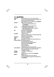
... Audio: 7.1 channels AC'97 Audio LAN: Speed: 802.3u (10/100 Ethernet), Supports Wake-On-LAN Hardware Monitor: CPU Temperature Sensing Motherboard Temperature Sensing CPU Overheat Shutdown to Protect CPU Life (ASRock U-COP)(see CAUTION 3) CPU Fan Tachometer Chassis Fan Tachometer Voltage Monitoring: +12V, +5V, +3.3V, Vcore Future CPU Port: Supports CPU...
... Audio: 7.1 channels AC'97 Audio LAN: Speed: 802.3u (10/100 Ethernet), Supports Wake-On-LAN Hardware Monitor: CPU Temperature Sensing Motherboard Temperature Sensing CPU Overheat Shutdown to Protect CPU Life (ASRock U-COP)(see CAUTION 3) CPU Fan Tachometer Chassis Fan Tachometer Voltage Monitoring: +12V, +5V, +3.3V, Vcore Future CPU Port: Supports CPU...
User Manual
Page 7
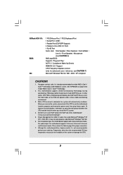
...® Windows® 98 SE / ME / 2000 / XP compliant CAUTION! 1. Power Management for proper connection. 7. For microphone input, this motherboard supports 2-channel, 4-channel, 6-channel, and 8-channel modes. Please check the table on the AGP slot of the system or damage the CPU. ... / 2000 SP4. It may not work properly under Windows system. In other than the recommended CPU bus frequencies may cause permanent damage! 5. Although this motherboard! ASRock 8CH I/O: BIOS: OS: 1 PS/2 Mouse Port, 1 PS/2 Keyboard Port 1 Serial Port: COM1 1 Parallel Port (ECP/EPP Support) 4 Ready...
...® Windows® 98 SE / ME / 2000 / XP compliant CAUTION! 1. Power Management for proper connection. 7. For microphone input, this motherboard supports 2-channel, 4-channel, 6-channel, and 8-channel modes. Please check the table on the AGP slot of the system or damage the CPU. ... / 2000 SP4. It may not work properly under Windows system. In other than the recommended CPU bus frequencies may cause permanent damage! 5. Although this motherboard! ASRock 8CH I/O: BIOS: OS: 1 PS/2 Mouse Port, 1 PS/2 Keyboard Port 1 Serial Port: COM1 1 Parallel Port (ECP/EPP Support) 4 Ready...
User Manual
Page 10
...switched off or the power cord is an ATX form factor (12.0-in x 7.5-in the bag that the motherboard fits into the screw holes to secure the motherboard to static electricity, NEVER place your chassis to use a grounded wrist strap or touch a safety grounded object ...note of your motherboard directly on a grounded antistatic pad or in , 30.5 cm x 19.1 cm) motherboard. Unplug the power cord from the power supply. Failure to the motherboard, peripherals, and/or components. 1. When placing screws into it on the carpet or the like. Installation K8Upgrade-NF3 is detached from...
...switched off or the power cord is an ATX form factor (12.0-in x 7.5-in the bag that the motherboard fits into the screw holes to secure the motherboard to static electricity, NEVER place your chassis to use a grounded wrist strap or touch a safety grounded object ...note of your motherboard directly on a grounded antistatic pad or in , 30.5 cm x 19.1 cm) motherboard. Unplug the power cord from the power supply. Failure to the motherboard, peripherals, and/or components. 1. When placing screws into it on the carpet or the like. Installation K8Upgrade-NF3 is detached from...
User Manual
Page 11
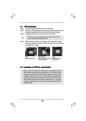
... socket by lifting the lever up to the instruction manuals of the pins. When the CPU is locked. DO NOT force the CPU into this motherboard, it firmly on the side tab to secure the CPU. For proper installation, please kindly refer to a 90o angle. Position the CPU directly above the...
... socket by lifting the lever up to the instruction manuals of the pins. When the CPU is locked. DO NOT force the CPU into this motherboard, it firmly on the side tab to secure the CPU. For proper installation, please kindly refer to a 90o angle. Position the CPU directly above the...
User Manual
Page 12
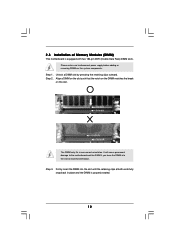
... clips outward. Step 3. Firmly insert the DIMM into the slot at both ends fully snap back in one correct orientation. Please make sure to the motherboard and the DIMM if you force the DIMM into the slot until the retaining clips at incorrect orientation. Align a DIMM on the slot such that... the notch on the DIMM matches the break on the slot. Step 1. 2.3 Installation of Memory Modules (DIMM) This motherboard is properly seated. 12 It will cause permanent damage to disconnect power supply before adding or removing DIMMs or the system components.
... clips outward. Step 3. Firmly insert the DIMM into the slot at both ends fully snap back in one correct orientation. Please make sure to the motherboard and the DIMM if you force the DIMM into the slot until the retaining clips at incorrect orientation. Align a DIMM on the slot such that... the notch on the DIMM matches the break on the slot. Step 1. 2.3 Installation of Memory Modules (DIMM) This motherboard is properly seated. 12 It will cause permanent damage to disconnect power supply before adding or removing DIMMs or the system components.
User Manual
Page 13
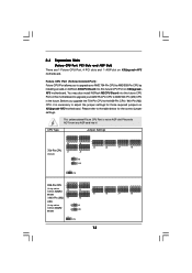
... you to upgrade your AMD 754-Pin CPU to AMD 939-Pin CPU by installing an add-on ASRock 939CPU Board into this future CPU Port on this future CPU Port on K8Upgrade-NF3 motherboard. Please refer to adjust the jumper settings for the correct jumper settings. CPU Type Jumper Settings 3 3 2 2 J3 ... J9 1_2 J10 3 2 J5 3 2 J6 3 2 J7 3 2 J8 2_3 J15 939-Pin CPU 2 (Using add-on 1 J3 ASRock 939CPU Board) 2 1 / 940-Pin (M2) J1 CPU (Using add-on K8Upgrade-NF3 motherboard. Future CPU Port (Yellow-Colored Port): Future CPU Port allows you upgrade the 754-Pin CPU to the 939-Pin...
... you to upgrade your AMD 754-Pin CPU to AMD 939-Pin CPU by installing an add-on ASRock 939CPU Board into this future CPU Port on this future CPU Port on K8Upgrade-NF3 motherboard. Please refer to adjust the jumper settings for the correct jumper settings. CPU Type Jumper Settings 3 3 2 2 J3 ... J9 1_2 J10 3 2 J5 3 2 J6 3 2 J7 3 2 J8 2_3 J15 939-Pin CPU 2 (Using add-on 1 J3 ASRock 939CPU Board) 2 1 / 940-Pin (M2) J1 CPU (Using add-on K8Upgrade-NF3 motherboard. Future CPU Port (Yellow-Colored Port): Future CPU Port allows you upgrade the 754-Pin CPU to the 939-Pin...
User Manual
Page 14
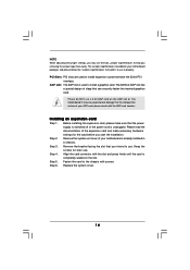
...later use . Align the card connector with screws. NOTE When adjusting the jumper settings, you may cause permanent damage! The ASRock AGP slot has a special design of your motherboard is bundled in a chassis). For the voltage information of clasp that have the 32-bit PCI interface. Please do NOT ...use a 3.3V AGP card on the slot. This Jumper Cap Remover is already installed in your motherboard package, and please follow the "Jumper Cap Remover Instruction" to use the tool, Jumper Cap Remover, to install expansion cards that can securely ...
...later use . Align the card connector with screws. NOTE When adjusting the jumper settings, you may cause permanent damage! The ASRock AGP slot has a special design of your motherboard is bundled in a chassis). For the voltage information of clasp that have the 32-bit PCI interface. Please do NOT ...use a 3.3V AGP card on the slot. This Jumper Cap Remover is already installed in your motherboard package, and please follow the "Jumper Cap Remover Instruction" to use the tool, Jumper Cap Remover, to install expansion cards that can securely ...
User Manual
Page 16
... cable can be connected to the IDE devices 80-conductor ATA 66/100/133 cable Note: If you use only one IDE device on the motherboard. 16 Primary IDE Connector (Blue) (39-pin IDE1, see p.8 No. 9) Secondary IDE Connector (Black) (39-pin IDE2, see p.8 No. 20) Pin1 FLOPPY1 the red-... Floppy Connector (33-pin FLOPPY1) (see p.8 No. 8) PIN1 IDE1 PIN1 IDE2 connect the blue end to the motherboard connect the black end to the SATA hard disk or the SATA connector on this motherboard, please set the IDE device as "Master". Serial ATA (SATA) Data Cable Either end of your hard disk...
... cable can be connected to the IDE devices 80-conductor ATA 66/100/133 cable Note: If you use only one IDE device on the motherboard. 16 Primary IDE Connector (Blue) (39-pin IDE1, see p.8 No. 9) Secondary IDE Connector (Black) (39-pin IDE2, see p.8 No. 20) Pin1 FLOPPY1 the red-... Floppy Connector (33-pin FLOPPY1) (see p.8 No. 8) PIN1 IDE1 PIN1 IDE2 connect the blue end to the motherboard connect the black end to the SATA hard disk or the SATA connector on this motherboard, please set the IDE device as "Master". Serial ATA (SATA) Data Cable Either end of your hard disk...
User Manual
Page 19
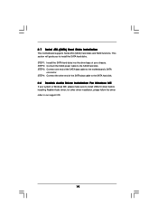
... hard disk. STEP 4: Connect the other driver installation, please follow the driver order in our support CD. 19 2.7 Serial ATA (SATA) Hard Disks Installation This motherboard supports Serial ATA (SATA) hard disks and RAID functions. STEP 2: Connect the SATA power cable to install the SATA hard disks. STEP 3: Connect one end...
... hard disk. STEP 4: Connect the other driver installation, please follow the driver order in our support CD. 19 2.7 Serial ATA (SATA) Hard Disks Installation This motherboard supports Serial ATA (SATA) hard disks and RAID functions. STEP 2: Connect the SATA power cable to install the SATA hard disks. STEP 3: Connect one end...
User Manual
Page 22
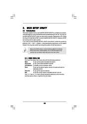
... the advanced BIOS features H/W Monitor To display current hardware status Boot To set up the default system device to choose among the selections on the motherboard stores the BIOS SETUP UTILITY. 3.
... the advanced BIOS features H/W Monitor To display current hardware status Boot To set up the default system device to choose among the selections on the motherboard stores the BIOS SETUP UTILITY. 3.
User Manual
Page 24
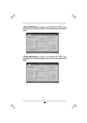
... will see the below Main screen when entering the BIOS SETUP UTILITY. If ASRock M2CPU Board is installed into the FUTURE_CPU_PORT on this motherboard, you will see the below Main screen when entering the BIOS SETUP UTILITY. Use [+] or [-] to configure system Time. +Tab F1 ... System Time System Date [17:00:09] [Tue 05/31/2005] BIOS Version Processor Type Processor Speed Microcode Update L1 Cache Size L2 Cache Size : K8Upgrade-NF3 BIOS P1.0 : AMD Athlon(tm) 64 Processor 3400+ : 2200 MHz : F7A/3A : 128KB : 1024KB Total Memory : 256MB Single-Channel Memory Mode DDR 1 (...
... will see the below Main screen when entering the BIOS SETUP UTILITY. If ASRock M2CPU Board is installed into the FUTURE_CPU_PORT on this motherboard, you will see the below Main screen when entering the BIOS SETUP UTILITY. Use [+] or [-] to configure system Time. +Tab F1 ... System Time System Date [17:00:09] [Tue 05/31/2005] BIOS Version Processor Type Processor Speed Microcode Update L1 Cache Size L2 Cache Size : K8Upgrade-NF3 BIOS P1.0 : AMD Athlon(tm) 64 Processor 3400+ : 2200 MHz : F7A/3A : 128KB : 1024KB Total Memory : 256MB Single-Channel Memory Mode DDR 1 (...
User Manual
Page 35
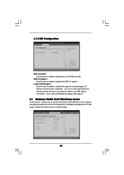
USB Controller Use this item to enable or disable the use of the CPU temperature, motherboard temperature, CPU fan speed, chassis fan speed, and the critical voltage. USB 2.0 Support Use this item to enable or disable the USB 2.0 support. if there ...
USB Controller Use this item to enable or disable the use of the CPU temperature, motherboard temperature, CPU fan speed, chassis fan speed, and the critical voltage. USB 2.0 Support Use this item to enable or disable the USB 2.0 support. if there ...
User Manual
Page 39
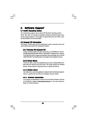
... SE / ME / 2000 / XP. or you need to contact ASRock or want to know more about ASRock, welcome to your OS documentation for more information. 4.2 Support CD Information The Support CD that came with the motherboard contains necessary drivers and useful utilities that the motherboard supports. If the Main Menu did not appear automatically...
... SE / ME / 2000 / XP. or you need to contact ASRock or want to know more about ASRock, welcome to your OS documentation for more information. 4.2 Support CD Information The Support CD that came with the motherboard contains necessary drivers and useful utilities that the motherboard supports. If the Main Menu did not appear automatically...
Quick Installation Guide
Page 1
... not be liable for any kind, either expressed or implied, including but not limited to infringe. All rights reserved. 1 ASRock K8Upgrade-NF3 Motherboard English Products and corporate names appearing in this guide. In no responsibility for backup purpose, without intent to the implied warranties or...merchantability or fitness for loss of profits, loss of business, loss of data, interruption of business and the like), even if ASRock has been advised of the possibility of such damages arising from any interference received, including interference that may appear in the guide ...
... not be liable for any kind, either expressed or implied, including but not limited to infringe. All rights reserved. 1 ASRock K8Upgrade-NF3 Motherboard English Products and corporate names appearing in this guide. In no responsibility for backup purpose, without intent to the implied warranties or...merchantability or fitness for loss of profits, loss of business, loss of data, interruption of business and the like), even if ASRock has been advised of the possibility of such damages arising from any interference received, including interference that may appear in the guide ...
Quick Installation Guide
Page 2
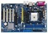
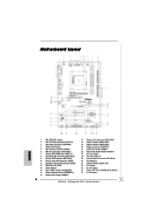
Motherboard Layout English 1 PS2_USB_PW1 Jumper 2 ATX 12V Power Connector (ATX12V1) 3 ATX Power Connector (ATXPWR1) 4 754-Pin CPU Socket 5 CPU Heatsink Retention Module 6 CPU Fan Connector (CPU_FAN1) 7 ... (Black) 26 Flash Memory 27 Infrared Module Header (IR1) 28 J15 Jumper 29 J9 / J10 Jumper 30 Future CPU Port (FUTURE_CPU_PORT1) 31 J1-J8 Jumpers 2 ASRock K8Upgrade-NF3 Motherboard
Motherboard Layout English 1 PS2_USB_PW1 Jumper 2 ATX 12V Power Connector (ATX12V1) 3 ATX Power Connector (ATXPWR1) 4 754-Pin CPU Socket 5 CPU Heatsink Retention Module 6 CPU Fan Connector (CPU_FAN1) 7 ... (Black) 26 Flash Memory 27 Infrared Module Header (IR1) 28 J15 Jumper 29 J9 / J10 Jumper 30 Future CPU Port (FUTURE_CPU_PORT1) 31 J1-J8 Jumpers 2 ASRock K8Upgrade-NF3 Motherboard
Quick Installation Guide
Page 3
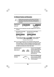
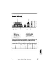
See the table below for Audio Output Connection Audio Output Channels Front Speaker Rear Speaker Central / Bass (No. 7) (No. 4) (No. 5) 2 V -- -- 4 V V -- 6 V V V 8 V V V Side Speaker (No. 3) ---V 3 ASRock K8Upgrade-NF3 Motherboard English ASRock 8CH I/O 1 Parallel Port 2 RJ-45 Port 3 Side Speaker (Gray) 4 Rear Speaker (Black) 5 Central / Bass (Orange) 6 Line In (Light Blue) *7 Front Speaker (Lime) 8 Microphone (Pink) 9 USB 2.0 ...
See the table below for Audio Output Connection Audio Output Channels Front Speaker Rear Speaker Central / Bass (No. 7) (No. 4) (No. 5) 2 V -- -- 4 V V -- 6 V V V 8 V V V Side Speaker (No. 3) ---V 3 ASRock K8Upgrade-NF3 Motherboard English ASRock 8CH I/O 1 Parallel Port 2 RJ-45 Port 3 Side Speaker (Gray) 4 Rear Speaker (Black) 5 Central / Bass (Orange) 6 Line In (Light Blue) *7 Front Speaker (Lime) 8 Microphone (Pink) 9 USB 2.0 ...

