User Manual
Page 3
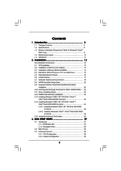
Installation 12 Pre-installation Precautions 12 2.1 CPU Installation 13 2.2 Installation of CPU Fan and Heatsink 13 2.3 Installation of Memory Modules (DIMM 14 2.4 Expansion Slots (PCI Express, PCI, and HDMR Slots 15 2.5 Easy Multi Monitor Feature 16 2.6 Jumpers ... 26 2.15 Untied Overclocking Technology 26 3 . BIOS SETUP UTILITY 27 3.1 Introduction 27 3.1.1 BIOS Menu Bar 27 3.1.2 Navigation Keys 28 3.2 Main Screen 29 3.3 Advanced Screen 29 3.3.1 CPU Configuration 29 3.3.2 Chipset Configuration 32 3 Contents 1 .
Installation 12 Pre-installation Precautions 12 2.1 CPU Installation 13 2.2 Installation of CPU Fan and Heatsink 13 2.3 Installation of Memory Modules (DIMM 14 2.4 Expansion Slots (PCI Express, PCI, and HDMR Slots 15 2.5 Easy Multi Monitor Feature 16 2.6 Jumpers ... 26 2.15 Untied Overclocking Technology 26 3 . BIOS SETUP UTILITY 27 3.1 Introduction 27 3.1.1 BIOS Menu Bar 27 3.1.2 Navigation Keys 28 3.2 Main Screen 29 3.3 Advanced Screen 29 3.3.1 CPU Configuration 29 3.3.2 Chipset Configuration 32 3 Contents 1 .

User Manual
Page 5
...) 1 x ASRock K8NF6G-VSTA Quick Installation Guide 1 x ASRock K8NF6G-VSTA Support CD 1 x Ultra ATA 66/100/133 IDE Ribbon Cable (80-conductor) 1 x 3.5-in Floppy Drive Ribbon Cable 1 x Serial ATA (SATA) Data Cable (Optional) 1 x Serial ATA (SATA) HDD Power Cable (Optional) 1 x HD 8CH I/O Shield 1 x COM Port Bracket 1 x HDMR Card (Optional) 5 You may find the latest VGA cards and CPU...
...) 1 x ASRock K8NF6G-VSTA Quick Installation Guide 1 x ASRock K8NF6G-VSTA Support CD 1 x Ultra ATA 66/100/133 IDE Ribbon Cable (80-conductor) 1 x 3.5-in Floppy Drive Ribbon Cable 1 x Serial ATA (SATA) Data Cable (Optional) 1 x Serial ATA (SATA) HDD Power Cable (Optional) 1 x HD 8CH I/O Shield 1 x COM Port Bracket 1 x HDMR Card (Optional) 5 You may find the latest VGA cards and CPU...
User Manual
Page 6
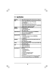
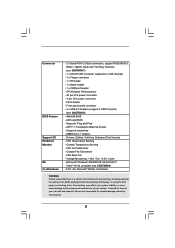
...-LAN HD 8CH I /O - Chipset capable to -Use USB 2.0 Ports - 1 x RJ-45 Port - Support DDR400/333/266 - Max. Max. 1.2 Specifications Platform CPU Chipset Memory Hybrid Booster Expansion Slot Graphics Audio LAN Rear Panel I /O - 1 x PS/2 Mouse Port - 1 x PS/2 Keyboard Port - 1 x VGA Port .../ nForce 405 - 2 x DDR DIMM slots - Pixel Shader 3.0 - shared memory 256MB - Speed: 10/100 Ethernet - CPU Frequency Stepless Control (see CAUTION 4) - ASRock U-COP (see CAUTION 3) - Integrated NVIDIA® GeForce6-class graphics DX9.0 VGA - Realtek PHY RTL8201CL - Micro ATX Form Factor...
...-LAN HD 8CH I /O - Chipset capable to -Use USB 2.0 Ports - 1 x RJ-45 Port - Support DDR400/333/266 - Max. Max. 1.2 Specifications Platform CPU Chipset Memory Hybrid Booster Expansion Slot Graphics Audio LAN Rear Panel I /O - 1 x PS/2 Mouse Port - 1 x PS/2 Keyboard Port - 1 x VGA Port .../ nForce 405 - 2 x DDR DIMM slots - Pixel Shader 3.0 - shared memory 256MB - Speed: 10/100 Ethernet - CPU Frequency Stepless Control (see CAUTION 4) - ASRock U-COP (see CAUTION 3) - Integrated NVIDIA® GeForce6-class graphics DX9.0 VGA - Realtek PHY RTL8201CL - Micro ATX Form Factor...
User Manual
Page 7
...) - 1 x Floppy connector - 1 x IR header - 1 x Game header - 1 x COM port header - Supports "Plug and Play" - Supports jumperfree - CPU Fan Tachometer - FCC, CE, Microsoft® WHQL Certificated WARNING Please realize that there is a certain risk involved with overclocking, including adjusting the setting in header... - AMI Legal BIOS - SMBIOS 2.3.1 Support - CPU Quiet Fan - Voltage Monitoring: +12V, +5V, +3.3V, Vcore - CPU/Chassis FAN connector - 20 pin ATX power connector - 4 pin 12V power connector - It ...
...) - 1 x Floppy connector - 1 x IR header - 1 x Game header - 1 x COM port header - Supports "Plug and Play" - Supports jumperfree - CPU Fan Tachometer - FCC, CE, Microsoft® WHQL Certificated WARNING Please realize that there is a certain risk involved with overclocking, including adjusting the setting in header... - AMI Legal BIOS - SMBIOS 2.3.1 Support - CPU Quiet Fan - Voltage Monitoring: +12V, +5V, +3.3V, Vcore - CPU/Chassis FAN connector - 20 pin ATX power connector - 4 pin 12V power connector - It ...
User Manual
Page 8
...hard disk drive to SATAII connector directly. 8. ASRock website http://www.asrock.com 8 To improve heat dissipation, remember to spray thermal grease between the CPU and the heatsink when you resume the system, please check if the CPU fan on page 11 for USB 2.0 works ... VistaTM 64-bit driver keeps on page 26 for Microsoft® Windows® VistaTM / VistaTM 64-bit driver and related information. While CPU overheat is strongly recommended to enable AMD's Cool 'n' QuietTM technology. 2. Before you install the PC system. 5. This motherboard supports Untied Overclocking...
...hard disk drive to SATAII connector directly. 8. ASRock website http://www.asrock.com 8 To improve heat dissipation, remember to spray thermal grease between the CPU and the heatsink when you resume the system, please check if the CPU fan on page 11 for USB 2.0 works ... VistaTM 64-bit driver keeps on page 26 for Microsoft® Windows® VistaTM / VistaTM 64-bit driver and related information. While CPU overheat is strongly recommended to enable AMD's Cool 'n' QuietTM technology. 2. Before you install the PC system. 5. This motherboard supports Untied Overclocking...

User Manual
Page 9
CPU Memory VGA Sempron 2500+ 512MB Single Channel* DX9.0 with WDDM Driver * If you use onboard VGA with total system memory size above 512MB and plan ...
CPU Memory VGA Sempron 2500+ 512MB Single Channel* DX9.0 with WDDM Driver * If you use onboard VGA with total system memory size above 512MB and plan ...

User Manual
Page 10
...45 ATXPWR1 ATX12V1 Socket 754 RAID RoHS NVIDIA GeForce 6100 / nForce 405 Chipset Super I/O 4Mb BIOS CD1 LAN PHY AUDIO CODEC 1 HD_AUDIO1 PCIE1 K8NF6G-VSTA PCI1 PCI EXPRESS PCI2 USB2.0 USB6_7 1 PCIE2 7.1CH HD HDMR1 GAME1 1 CMOS BATTERY CLRCMOS1 1 FLOPPY1 IR1 1 USB4_5 1 CHA_FAN1 PANEL 1 ...17 16 15 14 13 12 11 SATAII_2 SATAII_1 SATAII 24.4cm (9.6-in) 4 5 6 7 8 9 10 1 PS2_USB_PW1 Jumper 15 Floppy Connector (FLOPPY1) 2 CPU Fan Connector (CPU_FAN1) 16 Clear CMOS Jumper (CLRCMOS1) 3 184-pin DDR DIMM Slots (DDR1- 2) 17 Game Port Header (GAME1) 4 Primary SATAII Connector (...
...45 ATXPWR1 ATX12V1 Socket 754 RAID RoHS NVIDIA GeForce 6100 / nForce 405 Chipset Super I/O 4Mb BIOS CD1 LAN PHY AUDIO CODEC 1 HD_AUDIO1 PCIE1 K8NF6G-VSTA PCI1 PCI EXPRESS PCI2 USB2.0 USB6_7 1 PCIE2 7.1CH HD HDMR1 GAME1 1 CMOS BATTERY CLRCMOS1 1 FLOPPY1 IR1 1 USB4_5 1 CHA_FAN1 PANEL 1 ...17 16 15 14 13 12 11 SATAII_2 SATAII_1 SATAII 24.4cm (9.6-in) 4 5 6 7 8 9 10 1 PS2_USB_PW1 Jumper 15 Floppy Connector (FLOPPY1) 2 CPU Fan Connector (CPU_FAN1) 16 Clear CMOS Jumper (CLRCMOS1) 3 184-pin DDR DIMM Slots (DDR1- 2) 17 Game Port Header (GAME1) 4 Primary SATAII Connector (...

User Manual
Page 13
...to dissipate heat. You also need to spray thermal grease between the CPU and the heatsink to the CPU FAN connector (CPU_FAN1, see Page 10, No. 2). The lever clicks on the socket while you install the CPU into this motherboard, it is necessary to install a larger heatsink and... cooling fan to secure the CPU. Then connect the CPU fan to improve heat dissipation. Position the CPU directly above the socket such that the CPU and the heatsink are securely fastened and in place. 2.1 CPU Installation Step 1. Step 3. Make sure that the CPU corner with the golden triangle matches ...
...to dissipate heat. You also need to spray thermal grease between the CPU and the heatsink to the CPU FAN connector (CPU_FAN1, see Page 10, No. 2). The lever clicks on the socket while you install the CPU into this motherboard, it is necessary to install a larger heatsink and... cooling fan to secure the CPU. Then connect the CPU fan to improve heat dissipation. Position the CPU directly above the socket such that the CPU and the heatsink are securely fastened and in place. 2.1 CPU Installation Step 1. Step 3. Make sure that the CPU corner with the golden triangle matches ...

User Manual
Page 20
... (4-pin ATX12V1) (see p.10 No. 2) FAN_SPEED_CONTROL 4 CPU_FAN_SPEED 3 +12V 2 GND 1 Please connect the CPU fan cable to this motherboard provides 4-Pin CPU fan (Quiet Fan) support, the 3-Pin CPU fan still can work successfully even without the fan speed control function. If you plan to connect the 3-Pin... CPU fan to the CPU fan connector on the lower right hand taskbar to Pin 1-3. Click the icon on this connector. CPU Fan Connector (4-pin CPU_FAN1) (see p.10 No. 8) Please note that it...
... (4-pin ATX12V1) (see p.10 No. 2) FAN_SPEED_CONTROL 4 CPU_FAN_SPEED 3 +12V 2 GND 1 Please connect the CPU fan cable to this motherboard provides 4-Pin CPU fan (Quiet Fan) support, the 3-Pin CPU fan still can work successfully even without the fan speed control function. If you plan to connect the 3-Pin... CPU fan to the CPU fan connector on the lower right hand taskbar to Pin 1-3. Click the icon on this connector. CPU Fan Connector (4-pin CPU_FAN1) (see p.10 No. 8) Please note that it...
User Manual
Page 26
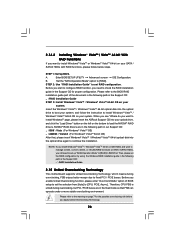
... you want to install Windows?" Enter BIOS SETUP UTILITY Advanced screen IDE Configuration. page, please insert the ASRock Support CD into your system. Then, please set the selection from [Auto] to [CPU, PCIE, Async.]. STEP 1: Set Up BIOS. Before you start to configure RAID function, you need ... 64-bit on your system. STEP 2: Use "RAID Installation Guide" to set up "SATA Operation Mode" to fixed PCI / PCIE buses. Therefore, CPU FSB is untied during overclocking, FSB enjoys better margin due to [RAID] in the Support CD for the possible overclocking risk before you want to...
... you want to install Windows?" Enter BIOS SETUP UTILITY Advanced screen IDE Configuration. page, please insert the ASRock Support CD into your system. Then, please set the selection from [Auto] to [CPU, PCIE, Async.]. STEP 1: Set Up BIOS. Before you start to configure RAID function, you need ... 64-bit on your system. STEP 2: Use "RAID Installation Guide" to set up "SATA Operation Mode" to fixed PCI / PCIE buses. Therefore, CPU FSB is untied during overclocking, FSB enjoys better margin due to [RAID] in the Support CD for the possible overclocking risk before you want to...
User Manual
Page 29
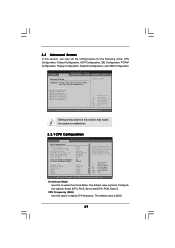
... wrong values in this section may cause the system to malfunction. 3.3.1 CPU Configuration BIOS SETUP UTILITY Advanced CPU Configuration Overclock Mode CPU Frequency (MHz) PCIE Frequency (MHz) Boot Failure Guard CPU/LDT Spread Spectrum PCIE Spread Spectrum SATA Spread Spectrum Cool' n' Quiet Processor... Advanced Settings WARNING : Setting wrong values in below sections may cause system to malfunction. CPU Configuration Chipset Configuration ACPI Configuration IDE Configuration PCIPnP Configuration Floppy Configuration SuperIO Configuration USB Configuration Options for the following items...
... wrong values in this section may cause the system to malfunction. 3.3.1 CPU Configuration BIOS SETUP UTILITY Advanced CPU Configuration Overclock Mode CPU Frequency (MHz) PCIE Frequency (MHz) Boot Failure Guard CPU/LDT Spread Spectrum PCIE Spread Spectrum SATA Spread Spectrum Cool' n' Quiet Processor... Advanced Settings WARNING : Setting wrong values in below sections may cause system to malfunction. CPU Configuration Chipset Configuration ACPI Configuration IDE Configuration PCIPnP Configuration Floppy Configuration SuperIO Configuration USB Configuration Options for the following items...
User Manual
Page 30
...set to [0.75% Hershey] as default. BIOS SETUP UTILITY BIOS SETUP UTILITY Advanced CPU Configuration Overclock Mode CPU Frequency (MHz) PCIE Frequency (MHz) Boot Failure Guard CPU/LDT Spread Spectrum PCIE Spread Spectrum SATA Spread Spectrum Cool' n' Quiet Processor Maximum ...], [0.5% Triangular], and [0.75% Triangular]. Configuration options: [Disabled], and [Enabled]. If you may reduce CPU voltage and memory frequency, and lead to [Auto] by default. CPU/LDT Spread Spectrum This feature will be left at the rated frequency/voltage. PCIE Spread Spectrum This feature will...
...set to [0.75% Hershey] as default. BIOS SETUP UTILITY BIOS SETUP UTILITY Advanced CPU Configuration Overclock Mode CPU Frequency (MHz) PCIE Frequency (MHz) Boot Failure Guard CPU/LDT Spread Spectrum PCIE Spread Spectrum SATA Spread Spectrum Cool' n' Quiet Processor Maximum ...], [0.5% Triangular], and [0.75% Triangular]. Configuration options: [Disabled], and [Enabled]. If you may reduce CPU voltage and memory frequency, and lead to [Auto] by default. CPU/LDT Spread Spectrum This feature will be left at the rated frequency/voltage. PCIE Spread Spectrum This feature will...

User Manual
Page 31
... the means of the standard values as listed: [133 MHz (DDR266)], [166 MHz (DDR333)], [200 MHz (DDR400)]. The range of the value depends on the CPU you adopt on this motherboard. Burst Length Burst length can be set to 8, 4 or 2 beats. 64 Bit Dq must use the 4 beats. 31 The range... of the value depends on the CPU you adopt on this motherboard. Memory Clock This item can be set by the code using [Auto]. The default value is [Auto]. Configuration options: [Auto...
... the means of the standard values as listed: [133 MHz (DDR266)], [166 MHz (DDR333)], [200 MHz (DDR400)]. The range of the value depends on the CPU you adopt on this motherboard. Burst Length Burst length can be set to 8, 4 or 2 beats. 64 Bit Dq must use the 4 beats. 31 The range... of the value depends on the CPU you adopt on this motherboard. Memory Clock This item can be set by the code using [Auto]. The default value is [Auto]. Configuration options: [Auto...

User Manual
Page 32
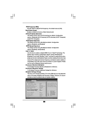
...Chipset Settings Onboard LAN Onboard HD Audio Front Panel Controller Share Memory Primary Graphics Adapter [Enabled] [Auto] [Auto] [Auto] [PCI] CPU-NB Link Speed CPU-NB Kink Width DRAM Voltage [Auto] [Auto] [Auto] To set share memory feature. NB Link Speed This feature allows you to... [Enabled] or [Disabled] for the onboard HD Audio feature. Configuration options: [PCI], [Onboard] and [PCI Express]. If you to NB link width. CPU - Configuration options: [Auto], [8 bit], and [16 bit]. DRAM Voltage Use this feature is [Auto]. The default value is plugged. NB Link Width ...
...Chipset Settings Onboard LAN Onboard HD Audio Front Panel Controller Share Memory Primary Graphics Adapter [Enabled] [Auto] [Auto] [Auto] [PCI] CPU-NB Link Speed CPU-NB Kink Width DRAM Voltage [Auto] [Auto] [Auto] To set share memory feature. NB Link Speed This feature allows you to... [Enabled] or [Disabled] for the onboard HD Audio feature. Configuration options: [PCI], [Onboard] and [PCI Express]. If you to NB link width. CPU - Configuration options: [Auto], [8 bit], and [16 bit]. DRAM Voltage Use this feature is [Auto]. The default value is plugged. NB Link Width ...

User Manual
Page 39
...) such as mouse, keyboard, USB flash... BIOS SETUP UTILITY Main Advanced H/W Monitor Boot Security Exit Hardware Health Event Monitoring CPU Temperature M / B Temperature CPU Fan Speed Chassis Fan Speed Vcore + 3.30V + 5.00V + 12.00V CPU Quiet Fan : 37 C / 98 F : 31 C / 87 F : 2833 RPM : N/A : 1.532 V : 3.129 V : 4.877 V... section, it allows you to monitor the status of the hardware on your system, including the parameters of the CPU temperature, motherboard temperature, CPU fan speed, chassis fan speed, and the critical voltage. The default value is no USB device connected, "Auto...
...) such as mouse, keyboard, USB flash... BIOS SETUP UTILITY Main Advanced H/W Monitor Boot Security Exit Hardware Health Event Monitoring CPU Temperature M / B Temperature CPU Fan Speed Chassis Fan Speed Vcore + 3.30V + 5.00V + 12.00V CPU Quiet Fan : 37 C / 98 F : 31 C / 87 F : 2833 RPM : N/A : 1.532 V : 3.129 V : 4.877 V... section, it allows you to monitor the status of the hardware on your system, including the parameters of the CPU temperature, motherboard temperature, CPU fan speed, chassis fan speed, and the critical voltage. The default value is no USB device connected, "Auto...

Quick Installation Guide
Page 2
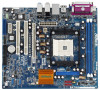
Motherboard Layout English 1 PS2_USB_PW1 Jumper 15 Floppy Connector (FLOPPY1) 2 CPU Fan Connector (CPU_FAN1) 16 Clear CMOS Jumper (CLRCMOS1) 3 184-pin DDR DIMM Slots (DDR1- 2) 17 Game Port Header (GAME1) 4 Primary SATAII Connector (SATAII_1, Red) 18 ... Connector (CHA_FAN1) 25 ATX Power Connector (ATXPWR1) 12 System Panel Header (PANEL1) 26 Serial Port Connector (COM1) 13 Chassis Speaker Header (SPEAKER 1) 27 754-Pin CPU Socket 14 Infrared Module Header (IR1) 28 CPU Heatsink Retention Module 2 ASRock K8NF6G-VSTA Motherboard
Motherboard Layout English 1 PS2_USB_PW1 Jumper 15 Floppy Connector (FLOPPY1) 2 CPU Fan Connector (CPU_FAN1) 16 Clear CMOS Jumper (CLRCMOS1) 3 184-pin DDR DIMM Slots (DDR1- 2) 17 Game Port Header (GAME1) 4 Primary SATAII Connector (SATAII_1, Red) 18 ... Connector (CHA_FAN1) 25 ATX Power Connector (ATXPWR1) 12 System Panel Header (PANEL1) 26 Serial Port Connector (COM1) 13 Chassis Speaker Header (SPEAKER 1) 27 754-Pin CPU Socket 14 Infrared Module Header (IR1) 28 CPU Heatsink Retention Module 2 ASRock K8NF6G-VSTA Motherboard

Quick Installation Guide
Page 4
Introduction Thank you for purchasing ASRock K8NF6G-VSTA motherboard, a reliable motherboard produced under ASRock's consistently stringent quality control. This Quick Installation Guide contains introduction of the motherboard can be subject to quality and endurance. You may find the latest VGA cards and CPU support lists on ASRock website without notice. In case any modifications of this manual...
Introduction Thank you for purchasing ASRock K8NF6G-VSTA motherboard, a reliable motherboard produced under ASRock's consistently stringent quality control. This Quick Installation Guide contains introduction of the motherboard can be subject to quality and endurance. You may find the latest VGA cards and CPU support lists on ASRock website without notice. In case any modifications of this manual...

Quick Installation Guide
Page 5
... 2GB - Pixel Shader 3.0 - NVIDIA® GeForce 6100 / nForce 405 - 2 x DDR DIMM slots - Supports Untied Overclocking Technology (see CAUTION 3) - CPU Frequency Stepless Control (see CAUTION 2) - Supports Wake-On-LAN HD 8CH I /O - HD Audio Jack: Side Speaker/Rear Speaker/Central/Bass/ Line in , ... x HDMR slot - Supports Hyper-Transport Technology - Boot Failure Guard (B.F.G.) - 2 x PCI slots - 1 x PCI Express Graphics slot (see CAUTION 6) English 5 ASRock K8NF6G-VSTA Motherboard Realtek ALC861VD/ALC883 7.1 channel audio CODEC with High Definition audio - Realtek PHY RTL8201CL -
... 2GB - Pixel Shader 3.0 - NVIDIA® GeForce 6100 / nForce 405 - 2 x DDR DIMM slots - Supports Untied Overclocking Technology (see CAUTION 3) - CPU Frequency Stepless Control (see CAUTION 2) - Supports Wake-On-LAN HD 8CH I /O - HD Audio Jack: Side Speaker/Rear Speaker/Central/Bass/ Line in , ... x HDMR slot - Supports Hyper-Transport Technology - Boot Failure Guard (B.F.G.) - 2 x PCI slots - 1 x PCI Express Graphics slot (see CAUTION 6) English 5 ASRock K8NF6G-VSTA Motherboard Realtek ALC861VD/ALC883 7.1 channel audio CODEC with High Definition audio - Realtek PHY RTL8201CL -

Quick Installation Guide
Page 6
... adjusting the setting in header - It should be done at your system. English 6 ASRock K8NF6G-VSTA Motherboard Supports "Plug and Play" - CPU Temperature Sensing - Chassis Temperature Sensing - CPU Fan Tachometer - Overclocking may affect your system stability, or even cause damage to the components...see CAUTION 7) - 1 x ATA133 IDE connector (supports 2 x IDE devices) - 1 x Floppy connector - 1 x IR header - 1 x Game header - 1 x COM port header - CPU/Chassis FAN connector - 20 pin ATX power connector - 4 pin 12V power connector - ACPI 1.1 Compliance Wake Up Events -
... adjusting the setting in header - It should be done at your system. English 6 ASRock K8NF6G-VSTA Motherboard Supports "Plug and Play" - CPU Temperature Sensing - Chassis Temperature Sensing - CPU Fan Tachometer - Overclocking may affect your system stability, or even cause damage to the components...see CAUTION 7) - 1 x ATA133 IDE connector (supports 2 x IDE devices) - 1 x Floppy connector - 1 x IR header - 1 x Game header - 1 x COM port header - CPU/Chassis FAN connector - 20 pin ATX power connector - 4 pin 12V power connector - ACPI 1.1 Compliance Wake Up Events -

Quick Installation Guide
Page 7
...3. PCI Express Graphics slot (PCIE1) supports most of the system or damage the CPU. 4. This motherboard supports Untied Overclocking Technology. Frequencies other than the recommended CPU bus frequencies may cause the instability of the ATiTM and NVIDIA® graphics cards ...driver keeps on page 3 for Microsoft® Windows® VistaTM / VistaTM 64-bit driver and related information. ASRock website http://www.asrock.com 7 ASRock K8NF6G-VSTA Motherboard English See APPENDIX on page 22 for USB 2.0 works fine under Windows system. Although this motherboard offers stepless ...
...3. PCI Express Graphics slot (PCIE1) supports most of the system or damage the CPU. 4. This motherboard supports Untied Overclocking Technology. Frequencies other than the recommended CPU bus frequencies may cause the instability of the ATiTM and NVIDIA® graphics cards ...driver keeps on page 3 for Microsoft® Windows® VistaTM / VistaTM 64-bit driver and related information. ASRock website http://www.asrock.com 7 ASRock K8NF6G-VSTA Motherboard English See APPENDIX on page 22 for USB 2.0 works fine under Windows system. Although this motherboard offers stepless ...


