User Manual
Page 6
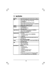
Socket 754 for AMD AthlonTM 64 and Sempron Processors - Supports AMD's Cool 'n' QuietTM Technology (see CAUTION 5) - 1 x PCI Express x1 slot - 1 x HDMR slot - Supports Hyper... 2 x PCI slots - 1 x PCI Express Graphics slot (see CAUTION 1) - Supports Untied Overclocking Technology (see CAUTION 3) - CPU Frequency Stepless Control (see CAUTION 2) - ASRock U-COP (see CAUTION 6) 6 Chipset capable to -Use USB 2.0 Ports - 1 x RJ-45 Port - 1.2 Specifications Platform CPU Chipset Memory Hybrid Booster Expansion Slot Graphics Audio LAN Rear Panel I /O - 1 x PS/2 Mouse Port - 1 x PS/2 ...
Socket 754 for AMD AthlonTM 64 and Sempron Processors - Supports AMD's Cool 'n' QuietTM Technology (see CAUTION 5) - 1 x PCI Express x1 slot - 1 x HDMR slot - Supports Hyper... 2 x PCI slots - 1 x PCI Express Graphics slot (see CAUTION 1) - Supports Untied Overclocking Technology (see CAUTION 3) - CPU Frequency Stepless Control (see CAUTION 2) - ASRock U-COP (see CAUTION 6) 6 Chipset capable to -Use USB 2.0 Ports - 1 x RJ-45 Port - 1.2 Specifications Platform CPU Chipset Memory Hybrid Booster Expansion Slot Graphics Audio LAN Rear Panel I /O - 1 x PS/2 Mouse Port - 1 x PS/2 ...

User Manual
Page 10
... Bottom: MIC IN 1 COM1 USB 2.0 T: USB2 B: USB3 USB 2.0 T: USB0 B: USB1 Top: RJ-45 ATXPWR1 ATX12V1 Socket 754 RAID RoHS NVIDIA GeForce 6100 / nForce 405 Chipset Super I/O 4Mb BIOS CD1 LAN PHY AUDIO CODEC 1 HD_AUDIO1 PCIE1 K8NF6G-VSTA PCI1 PCI EXPRESS PCI2 USB2.0 USB6_7 1 PCIE2 7.1CH HD HDMR1 GAME1 1 CMOS BATTERY CLRCMOS1 1 FLOPPY1 IR1... Connector (CHA_FAN1) 25 ATX Power Connector (ATXPWR1) 12 System Panel Header (PANEL1) 26 Serial Port Connector (COM1) 13 Chassis Speaker Header (SPEAKER 1) 27 754-Pin CPU Socket 14 Infrared Module Header (IR1) 28...
... Bottom: MIC IN 1 COM1 USB 2.0 T: USB2 B: USB3 USB 2.0 T: USB0 B: USB1 Top: RJ-45 ATXPWR1 ATX12V1 Socket 754 RAID RoHS NVIDIA GeForce 6100 / nForce 405 Chipset Super I/O 4Mb BIOS CD1 LAN PHY AUDIO CODEC 1 HD_AUDIO1 PCIE1 K8NF6G-VSTA PCI1 PCI EXPRESS PCI2 USB2.0 USB6_7 1 PCIE2 7.1CH HD HDMR1 GAME1 1 CMOS BATTERY CLRCMOS1 1 FLOPPY1 IR1... Connector (CHA_FAN1) 25 ATX Power Connector (ATXPWR1) 12 System Panel Header (PANEL1) 26 Serial Port Connector (COM1) 13 Chassis Speaker Header (SPEAKER 1) 27 754-Pin CPU Socket 14 Infrared Module Header (IR1) 28...

User Manual
Page 13
...After you push down the socket lever to indicate that the CPU corner with the golden triangle matches the socket corner with each other. Carefully insert the CPU into the socket to dissipate heat. The lever clicks on the socket while you install the CPU into this motherboard, it ...press it is locked. Lever 90° Up Socket Corner CPU Golden Triangle STEP 1: Lift Up The Socket Lever STEP 2 / STEP 3: STEP 4: Match The CPU Golden Triangle Push Down And Lock To The Socket Corner The Socket Lever 2.2 Installation of the CPU fan and the heatsink. 13 For proper installation, ...
...After you push down the socket lever to indicate that the CPU corner with the golden triangle matches the socket corner with each other. Carefully insert the CPU into the socket to dissipate heat. The lever clicks on the socket while you install the CPU into this motherboard, it ...press it is locked. Lever 90° Up Socket Corner CPU Golden Triangle STEP 1: Lift Up The Socket Lever STEP 2 / STEP 3: STEP 4: Match The CPU Golden Triangle Push Down And Lock To The Socket Corner The Socket Lever 2.2 Installation of the CPU fan and the heatsink. 13 For proper installation, ...

Quick Installation Guide
Page 2
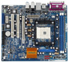
Motherboard Layout English 1 PS2_USB_PW1 Jumper 15 Floppy Connector (FLOPPY1) 2 CPU Fan Connector (CPU_FAN1) 16 Clear CMOS Jumper (CLRCMOS1) 3 184-pin DDR DIMM Slots (DDR1- 2) 17 Game Port Header (GAME1) 4 Primary SATAII Connector (SATAII_1, Red) 18 ... Connector (CHA_FAN1) 25 ATX Power Connector (ATXPWR1) 12 System Panel Header (PANEL1) 26 Serial Port Connector (COM1) 13 Chassis Speaker Header (SPEAKER 1) 27 754-Pin CPU Socket 14 Infrared Module Header (IR1) 28 CPU Heatsink Retention Module 2 ASRock K8NF6G-VSTA Motherboard
Motherboard Layout English 1 PS2_USB_PW1 Jumper 15 Floppy Connector (FLOPPY1) 2 CPU Fan Connector (CPU_FAN1) 16 Clear CMOS Jumper (CLRCMOS1) 3 184-pin DDR DIMM Slots (DDR1- 2) 17 Game Port Header (GAME1) 4 Primary SATAII Connector (SATAII_1, Red) 18 ... Connector (CHA_FAN1) 25 ATX Power Connector (ATXPWR1) 12 System Panel Header (PANEL1) 26 Serial Port Connector (COM1) 13 Chassis Speaker Header (SPEAKER 1) 27 754-Pin CPU Socket 14 Infrared Module Header (IR1) 28 CPU Heatsink Retention Module 2 ASRock K8NF6G-VSTA Motherboard

Quick Installation Guide
Page 5
Socket 754 for AMD AthlonTM 64 and Sempron Processors - Supports Untied Overclocking Technology (see CAUTION 3) - NVIDIA® GeForce 6100 / nForce 405 - 2 x DDR DIMM slots - CPU Frequency Stepless Control (see CAUTION 2) - ASRock U-COP (see CAUTION 5) - 1 x PCI Express x1 slot - 1 ... USB 2.0 Ports - 1 x RJ-45 Port - Supports Hyper-Transport Technology - Supports AMD's Cool 'n' QuietTM Technology (see CAUTION 6) English 5 ASRock K8NF6G-VSTA Motherboard Max. capacity: 2GB - Pixel Shader 3.0 - Realtek PHY RTL8201CL - Speed: 10/100 Ethernet - Micro ATX Form Factor: 9.6-in x ...
Socket 754 for AMD AthlonTM 64 and Sempron Processors - Supports Untied Overclocking Technology (see CAUTION 3) - NVIDIA® GeForce 6100 / nForce 405 - 2 x DDR DIMM slots - CPU Frequency Stepless Control (see CAUTION 2) - ASRock U-COP (see CAUTION 5) - 1 x PCI Express x1 slot - 1 ... USB 2.0 Ports - 1 x RJ-45 Port - Supports Hyper-Transport Technology - Supports AMD's Cool 'n' QuietTM Technology (see CAUTION 6) English 5 ASRock K8NF6G-VSTA Motherboard Max. capacity: 2GB - Pixel Shader 3.0 - Realtek PHY RTL8201CL - Speed: 10/100 Ethernet - Micro ATX Form Factor: 9.6-in x ...

Quick Installation Guide
Page 9
... so may damage the motherboard. 2.1 CPU Installation Step 1. Position the CPU directly above the socket such that comes with a small triangle. Carefully insert the CPU into the socket to secure the CPU. Step 5. When the CPU is locked. English 9 ASRock K8NF6G-VSTA Motherboard Unplug the power cord from the wall socket before you push down the socket lever to avoid bending of...
... so may damage the motherboard. 2.1 CPU Installation Step 1. Position the CPU directly above the socket such that comes with a small triangle. Carefully insert the CPU into the socket to secure the CPU. Step 5. When the CPU is locked. English 9 ASRock K8NF6G-VSTA Motherboard Unplug the power cord from the wall socket before you push down the socket lever to avoid bending of...


