User Manual
Page 3
... 1.5 HD 8CH I/O 11 2 . BIOS SETUP UTILITY 27 3.1 Introduction 27 3.1.1 BIOS Menu Bar 27 3.1.2 Navigation Keys 28 3.2 Main Screen 29 3.3 Advanced Screen 29 3.3.1 CPU Configuration 29 3.3.2 Chipset Configuration 32 3 Contents 1 .
... 1.5 HD 8CH I/O 11 2 . BIOS SETUP UTILITY 27 3.1 Introduction 27 3.1.1 BIOS Menu Bar 27 3.1.2 Navigation Keys 28 3.2 Main Screen 29 3.3 Advanced Screen 29 3.3.1 CPU Configuration 29 3.3.2 Chipset Configuration 32 3 Contents 1 .
User Manual
Page 6
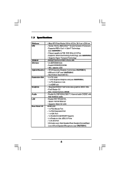
... Failure Guard (B.F.G.) - 2 x PCI slots - 1 x PCI Express Graphics slot (see CAUTION 4) - Speed: 10/100 Ethernet - Support DDR400/333/266 - ASRock U-COP (see CAUTION 5) - 1 x PCI Express x1 slot - 1 x HDMR slot - Pixel Shader 3.0 - 1.2 Specifications Platform CPU Chipset Memory Hybrid Booster Expansion Slot Graphics Audio LAN Rear Panel I /O - 1 x PS/2 Mouse Port - 1 x PS/2 Keyboard Port - 1 x VGA Port...
... Failure Guard (B.F.G.) - 2 x PCI slots - 1 x PCI Express Graphics slot (see CAUTION 4) - Speed: 10/100 Ethernet - Support DDR400/333/266 - ASRock U-COP (see CAUTION 5) - 1 x PCI Express x1 slot - 1 x HDMR slot - Pixel Shader 3.0 - 1.2 Specifications Platform CPU Chipset Memory Hybrid Booster Expansion Slot Graphics Audio LAN Rear Panel I /O - 1 x PS/2 Mouse Port - 1 x PS/2 Keyboard Port - 1 x VGA Port...

User Manual
Page 10
... USB 2.0 T: USB2 B: USB3 USB 2.0 T: USB0 B: USB1 Top: RJ-45 ATXPWR1 ATX12V1 Socket 754 RAID RoHS NVIDIA GeForce 6100 / nForce 405 Chipset Super I/O 4Mb BIOS CD1 LAN PHY AUDIO CODEC 1 HD_AUDIO1 PCIE1 K8NF6G-VSTA PCI1 PCI EXPRESS PCI2 USB2.0 USB6_7 1 PCIE2 7.1CH HD HDMR1 GAME1 1 CMOS BATTERY CLRCMOS1 1 FLOPPY1 IR1 1 USB4_5 1 CHA_FAN1 PANEL 1 PLED...
... USB 2.0 T: USB2 B: USB3 USB 2.0 T: USB0 B: USB1 Top: RJ-45 ATXPWR1 ATX12V1 Socket 754 RAID RoHS NVIDIA GeForce 6100 / nForce 405 Chipset Super I/O 4Mb BIOS CD1 LAN PHY AUDIO CODEC 1 HD_AUDIO1 PCIE1 K8NF6G-VSTA PCI1 PCI EXPRESS PCI2 USB2.0 USB6_7 1 PCIE2 7.1CH HD HDMR1 GAME1 1 CMOS BATTERY CLRCMOS1 1 FLOPPY1 IR1 1 USB4_5 1 CHA_FAN1 PANEL 1 PLED...

User Manual
Page 19
...-L GND GND CD-R CD1 Besides four default USB 2.0 ports on the I/O panel, there are for HD audio panel only. Enter Advanced Settings, and then select Chipset Configuration. This header supports an optional wireless transmitting and receiving infrared module. This connector allows you use AC'97 audio panel, please install it to...
...-L GND GND CD-R CD1 Besides four default USB 2.0 ports on the I/O panel, there are for HD audio panel only. Enter Advanced Settings, and then select Chipset Configuration. This header supports an optional wireless transmitting and receiving infrared module. This connector allows you use AC'97 audio panel, please install it to...

User Manual
Page 23
... ATAII (SATAII) hard disks and RAID functions. 2.9 Serial ATA (SATA) / Serial ATAII (SATAII) Hard Disks Installation This motherboard adopts NVIDIA® GeForce 6100 / nForce 405 chipset that it cannot perform Hot Plug if the OS has been installed into the drive bays of your chassis. This section will guide you install...
... ATAII (SATAII) hard disks and RAID functions. 2.9 Serial ATA (SATA) / Serial ATAII (SATAII) Hard Disks Installation This motherboard adopts NVIDIA® GeForce 6100 / nForce 405 chipset that it cannot perform Hot Plug if the OS has been installed into the drive bays of your chassis. This section will guide you install...
User Manual
Page 29
... and Exit Exit v02.54 (C) Copyright 1985-2003, American Megatrends, Inc. CPU Configuration Chipset Configuration ACPI Configuration IDE Configuration PCIPnP Configuration Floppy Configuration SuperIO Configuration USB Configuration Options for the following items: CPU Configuration..., Chipset Configuration, ACPI Configuration, IDE Configuration, PCIPnP Configuration, Floppy Configuration, SuperIO Configuration, and USB Configuration. Setting...
... and Exit Exit v02.54 (C) Copyright 1985-2003, American Megatrends, Inc. CPU Configuration Chipset Configuration ACPI Configuration IDE Configuration PCIPnP Configuration Floppy Configuration SuperIO Configuration USB Configuration Options for the following items: CPU Configuration..., Chipset Configuration, ACPI Configuration, IDE Configuration, PCIPnP Configuration, Floppy Configuration, SuperIO Configuration, and USB Configuration. Setting...

User Manual
Page 32
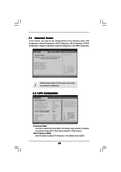
...], and [256MB]. Primary Graphics Adapter This item will be spread out over banks on the same node, or accross nodes, decreasing access contention. 3.3.2 Chipset Configuration BIOS SETUP UTILITY Advanced Chipset Settings Onboard LAN Onboard HD Audio Front Panel Controller Share Memory Primary Graphics Adapter [Enabled] [Auto] [Auto] [Auto] [PCI] CPU-NB Link...
...], and [256MB]. Primary Graphics Adapter This item will be spread out over banks on the same node, or accross nodes, decreasing access contention. 3.3.2 Chipset Configuration BIOS SETUP UTILITY Advanced Chipset Settings Onboard LAN Onboard HD Audio Front Panel Controller Share Memory Primary Graphics Adapter [Enabled] [Auto] [Auto] [Auto] [PCI] CPU-NB Link...

User Manual
Page 37
... Help Load Defaults Save and Exit Exit v02.54 (C) Copyright 1985-2003, American Megatrends, Inc. 3.3.7 Super IO Configuration BIOS SETUP UTILITY Advanced Configure Super IO Chipset OnBoard Floppy Controller Serial Port Address Infrared Port Address Parallel Port Address Parallel Port Mode EPP Version ECP Mode DMA Channel Parallel Port IRQ OnBoard...
... Help Load Defaults Save and Exit Exit v02.54 (C) Copyright 1985-2003, American Megatrends, Inc. 3.3.7 Super IO Configuration BIOS SETUP UTILITY Advanced Configure Super IO Chipset OnBoard Floppy Controller Serial Port Address Infrared Port Address Parallel Port Address Parallel Port Mode EPP Version ECP Mode DMA Channel Parallel Port IRQ OnBoard...

Quick Installation Guide
Page 5
Supports AMD's Cool 'n' QuietTM Technology (see CAUTION 5) - 1 x PCI Express x1 slot - 1 x HDMR slot - Chipset capable to -Use USB 2.0 Ports - 1 x RJ-45 Port - Support DDR400/333/266 - Max. Boot Failure Guard (B.F.G.) - 2 x PCI slots - 1 x PCI...CPU Chipset Memory Hybrid Booster Expansion Slot Graphics Audio LAN Rear Panel I /O - 1 x PS/2 Mouse Port - 1 x PS/2 Keyboard Port - 1 x VGA Port - 1 x Parallel Port (ECP/EPP Support) - 4 x Ready-to FSB 1000 MHz (2.0 GT/s) - NVIDIA® GeForce 6100 / nForce 405 - 2 x DDR DIMM slots - ASRock U-COP (see CAUTION 6) English 5 ASRock K8NF6G-VSTA ...
Supports AMD's Cool 'n' QuietTM Technology (see CAUTION 5) - 1 x PCI Express x1 slot - 1 x HDMR slot - Chipset capable to -Use USB 2.0 Ports - 1 x RJ-45 Port - Support DDR400/333/266 - Max. Boot Failure Guard (B.F.G.) - 2 x PCI slots - 1 x PCI...CPU Chipset Memory Hybrid Booster Expansion Slot Graphics Audio LAN Rear Panel I /O - 1 x PS/2 Mouse Port - 1 x PS/2 Keyboard Port - 1 x VGA Port - 1 x Parallel Port (ECP/EPP Support) - 4 x Ready-to FSB 1000 MHz (2.0 GT/s) - NVIDIA® GeForce 6100 / nForce 405 - 2 x DDR DIMM slots - ASRock U-COP (see CAUTION 6) English 5 ASRock K8NF6G-VSTA ...

Quick Installation Guide
Page 15
... four default USB 2.0 ports on the chassis must support HDA to MIC2_L. Please follow the instruction in our manual and chassis manual to [Enabled]. 15 ASRock K8NF6G-VSTA Motherboard English D. Enter BIOS Setup Utility. B. Enter Advanced Settings, and then select Chipset Configuration. Each USB 2.0 header can support two USB 2.0 ports.
... four default USB 2.0 ports on the chassis must support HDA to MIC2_L. Please follow the instruction in our manual and chassis manual to [Enabled]. 15 ASRock K8NF6G-VSTA Motherboard English D. Enter BIOS Setup Utility. B. Enter Advanced Settings, and then select Chipset Configuration. Each USB 2.0 header can support two USB 2.0 ports.

Quick Installation Guide
Page 19
... auto-detected and listed on and in working condition. 2.10 Driver Installation Guide To install the drivers to your system can work properly. 19 ASRock K8NF6G-VSTA Motherboard English STEP 1: Install the SATA / SATAII hard disks into the SATA / SATAII HDD. STEP 4: Connect the other end of your ... storage devices. 2.8 Serial ATA (SATA) / Serial ATAII (SATAII) Hard Disks Installation This motherboard adopts NVIDIA® GeForce 6100 / nForce 405 chipset that it cannot perform Hot Plug if the OS has been installed into the drive bays of the SATA data cable to your chassis. STEP...
... auto-detected and listed on and in working condition. 2.10 Driver Installation Guide To install the drivers to your system can work properly. 19 ASRock K8NF6G-VSTA Motherboard English STEP 1: Install the SATA / SATAII hard disks into the SATA / SATAII HDD. STEP 4: Connect the other end of your ... storage devices. 2.8 Serial ATA (SATA) / Serial ATAII (SATAII) Hard Disks Installation This motherboard adopts NVIDIA® GeForce 6100 / nForce 405 chipset that it cannot perform Hot Plug if the OS has been installed into the drive bays of the SATA data cable to your chassis. STEP...

