
User Manual
Page 1
K7VT6-C User Manual Version 1.0 Published December 2004 Copyright©2004 ASRock INC. All rights reserved. 1
K7VT6-C User Manual Version 1.0 Published December 2004 Copyright©2004 ASRock INC. All rights reserved. 1

User Manual
Page 2
... or omissions that may not cause harmful interference, and (2) this device must accept any defect or error in this manual. ASRock assumes no event shall ASRock, its directors, officers, employees, or agents be liable for any indirect, special, incidental, or consequential damages (including damages for... loss of profits, loss of business, loss of data, interruption of business and the like), even if ASRock has been advised of the possibility of such damages arising from any interference received, including interference that may appear in the manual or...
... or omissions that may not cause harmful interference, and (2) this device must accept any defect or error in this manual. ASRock assumes no event shall ASRock, its directors, officers, employees, or agents be liable for any indirect, special, incidental, or consequential damages (including damages for... loss of profits, loss of business, loss of data, interruption of business and the like), even if ASRock has been advised of the possibility of such damages arising from any interference received, including interference that may appear in the manual or...
User Manual
Page 3
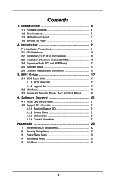
... 2.4 Expansion Slots (PCI and AGP Slots 12 2.5 Jumpers Setup 13 2.6 Onboard Headers and Connectors 15 3. Security Setup Menu 27 3. Introduction 4 1.1 Package Contents 4 1.2 Specifications 5 1.3 Motherboard Layout 7 1.4 ASRock I/O Plus 8 TM ...2. Exit Menu 30 3 Advanced BIOS Setup Menu 22 2.
... 2.4 Expansion Slots (PCI and AGP Slots 12 2.5 Jumpers Setup 13 2.6 Onboard Headers and Connectors 15 3. Security Setup Menu 27 3. Introduction 4 1.1 Package Contents 4 1.2 Specifications 5 1.3 Motherboard Layout 7 1.4 ASRock I/O Plus 8 TM ...2. Exit Menu 30 3 Advanced BIOS Setup Menu 22 2.

User Manual
Page 4
... stringent quality control. It delivers excellent performance with robust design conforming to ASRock's commitment to change without further notice. ASRock website http://www.asrock.com 1.1 Package Contents 1 x ASRock K7VT6-C Motherboard (ATX Form Factor: 12.0-in x 7.0-in, 30.5 cm x 17.8 cm) 1 x ASRock K7VT6-C Quick Installation Guide 1 x ASRock K7VT6-C Support CD 1 x Ultra ATA 66/100/133 IDE Ribbon Cable (80-conductor...
... stringent quality control. It delivers excellent performance with robust design conforming to ASRock's commitment to change without further notice. ASRock website http://www.asrock.com 1.1 Package Contents 1 x ASRock K7VT6-C Motherboard (ATX Form Factor: 12.0-in x 7.0-in, 30.5 cm x 17.8 cm) 1 x ASRock K7VT6-C Quick Installation Guide 1 x ASRock K7VT6-C Support CD 1 x Ultra ATA 66/100/133 IDE Ribbon Cable (80-conductor...

User Manual
Page 5
...802.3u (10/100 Ethernet), Supports Wake-On-LAN Hardware Monitor: CPU Temperature Sensing Motherboard Temperature Sensing CPU Overheat Shutdown to Protect CPU Life (ASRock U-COP)(see CAUTION 1) CPU Fan Tachometer Chassis Fan Tachometer Voltage Monitoring: +12V, +5V, +3.3V, Vcore PCI slots: 5 Slots with...1.5V, 8X/4X AGP Card (see CAUTION 2) USB 2.0: 6 USB 2.0 ports: include 6 ready-to-use USB 2.0 ports on the rear panel, (see CAUTION 3) ASRock I/O PlusTM: 1 PS/2 Mouse Port, 1 PS/2 Keyboard Port, 1 Serial Port: COM1, 1 Parallel Port (ECP/EPP Support) 6 ready-to-use USB 2.0 Ports, ...
...802.3u (10/100 Ethernet), Supports Wake-On-LAN Hardware Monitor: CPU Temperature Sensing Motherboard Temperature Sensing CPU Overheat Shutdown to Protect CPU Life (ASRock U-COP)(see CAUTION 1) CPU Fan Tachometer Chassis Fan Tachometer Voltage Monitoring: +12V, +5V, +3.3V, Vcore PCI slots: 5 Slots with...1.5V, 8X/4X AGP Card (see CAUTION 2) USB 2.0: 6 USB 2.0 ports: include 6 ready-to-use USB 2.0 ports on the rear panel, (see CAUTION 3) ASRock I/O PlusTM: 1 PS/2 Mouse Port, 1 PS/2 Keyboard Port, 1 Serial Port: COM1, 1 Parallel Port (ECP/EPP Support) 6 ready-to-use USB 2.0 Ports, ...

User Manual
Page 6
Power Management for advanced users' reference, see CAUTION 4) Microsoft® Windows® 98 SE / ME / 2000 / XP Compliant CAUTION! 1. It may not work properly under Microsoft® Windows® XP SP1/2000 SP4. Do NOT use a 3.3V AGP card on the motherboard functions properly and unplug the power cord, then plug it is detected, the system will automatically shutdown. It may cause the instability of your AMD CPU before you set the "CPU Host Frequency" configuration as "Manual" in the Support CD for "CPU Host Frequency" configuration. 6 Although this motherboard offers ...
Power Management for advanced users' reference, see CAUTION 4) Microsoft® Windows® 98 SE / ME / 2000 / XP Compliant CAUTION! 1. It may not work properly under Microsoft® Windows® XP SP1/2000 SP4. Do NOT use a 3.3V AGP card on the motherboard functions properly and unplug the power cord, then plug it is detected, the system will automatically shutdown. It may cause the instability of your AMD CPU before you set the "CPU Host Frequency" configuration as "Manual" in the Support CD for "CPU Host Frequency" configuration. 6 Although this motherboard offers ...

User Manual
Page 7
... B: USB1 IDE1 IDE2 25 USB 2.0 T: USB4 1 B: USB5 JUSB45 VIA KT600 CHIPSET Top: Line In Center: Line Out Bottom: Mic In 7 24 2Mb 8 BIOS FSB 400 K7VT6-C 23 22 21 20 19 LAN PHY GAME1 1 SUPER I/O AGP 8X 1.5V_AGP1 PCI1 DDR400 PCI2 1 FSB_SEL0 1 FSB_SEL1 1 FSB_SEL2 1 AUDIO1 JR1 JL1 CMOS BATTERY AUDIO CODEC...
... B: USB1 IDE1 IDE2 25 USB 2.0 T: USB4 1 B: USB5 JUSB45 VIA KT600 CHIPSET Top: Line In Center: Line Out Bottom: Mic In 7 24 2Mb 8 BIOS FSB 400 K7VT6-C 23 22 21 20 19 LAN PHY GAME1 1 SUPER I/O AGP 8X 1.5V_AGP1 PCI1 DDR400 PCI2 1 FSB_SEL0 1 FSB_SEL1 1 FSB_SEL2 1 AUDIO1 JR1 JL1 CMOS BATTERY AUDIO CODEC...

User Manual
Page 8
1.4 ASRock I/O PlusTM 1 2 3 4 5 11 10 9 1 Parallel Port 2 RJ-45 Port 3 Line In (Light Blue) 4 Line Out (Lime) 5 Microphone (Pink) 6 2 x Shared USB 2.0 Port (USB4, USB5) 8 7 6 7 2 x USB 2.0 Port (USB0, USB1) 8 2 x USB 2.0 Port (USB2, USB3) 9 Serial Port: COM1 10 PS/2 Keyboard Port (Purple) 11 PS/2 Mouse Port (Green) 8
1.4 ASRock I/O PlusTM 1 2 3 4 5 11 10 9 1 Parallel Port 2 RJ-45 Port 3 Line In (Light Blue) 4 Line Out (Lime) 5 Microphone (Pink) 6 2 x Shared USB 2.0 Port (USB4, USB5) 8 7 6 7 2 x USB 2.0 Port (USB0, USB1) 8 2 x USB 2.0 Port (USB2, USB3) 9 Serial Port: COM1 10 PS/2 Keyboard Port (Purple) 11 PS/2 Mouse Port (Green) 8

User Manual
Page 9
... the edges and do not over-tighten the screws! Doing so may cause severe damage to the chassis, please do not touch the ICs. 4. 2. Installation K7VT6-C is detached from the wall socket before you install the motherboard, study the configuration of the following precautions before touching any motherboard settings. Before you...
... the edges and do not over-tighten the screws! Doing so may cause severe damage to the chassis, please do not touch the ICs. 4. 2. Installation K7VT6-C is detached from the wall socket before you install the motherboard, study the configuration of the following precautions before touching any motherboard settings. Before you...

User Manual
Page 10
DO NOT force the CPU into the socket until it fits in place, press it is also needed to avoid bending of 600 MHz and higher require larger heatsink and cooling fan. Thermal grease between the CPU and the heatsink is locked. Position the CPU directly above the socket such that the CPU and the heatsink are securely fastened and in one correct orientation. The lever clicks on the socket while you push down the socket lever to indicate that it firmly on the side tab to secure the CPU. Step 1 Step 2, 3 Step 4 2.2 Installation of CPU Fan and Heatsink AMD AthlonTM / AthlonTM ...
DO NOT force the CPU into the socket until it fits in place, press it is also needed to avoid bending of 600 MHz and higher require larger heatsink and cooling fan. Thermal grease between the CPU and the heatsink is locked. Position the CPU directly above the socket such that the CPU and the heatsink are securely fastened and in one correct orientation. The lever clicks on the socket while you push down the socket lever to indicate that it firmly on the side tab to secure the CPU. Step 1 Step 2, 3 Step 4 2.2 Installation of CPU Fan and Heatsink AMD AthlonTM / AthlonTM ...

User Manual
Page 11
... system components. Align a DIMM on the slot such that the notch on the DIMM matches the break on the slot. 2.3 Installation of Memory Modules (DIMM) K7VT6-C motherboard provides two 184-pin DDR (Double Data Rate) DIMM slots. Please make sure to the motherboard and the DIMM if you force the DIMM...
... system components. Align a DIMM on the slot such that the notch on the DIMM matches the break on the slot. 2.3 Installation of Memory Modules (DIMM) K7VT6-C motherboard provides two 184-pin DDR (Double Data Rate) DIMM slots. Please make sure to the motherboard and the DIMM if you force the DIMM...

User Manual
Page 12
...expansion card, please make necessary hardware settings for later use a 3.3V AGP card on the AGP slot of your motherboard is completely seated on K7VT6-C motherboard. Remove the system unit cover (if your graphics card, please check with the graphics card vendors. Keep the screws for the card ...expansion cards that can securely fasten the inserted graphics card. Please do NOT use . Step 3. For the voltage information of this motherboard! The ASRock AGP slot has a special design of the expansion card and make sure that the power supply is switched off or the power cord is ...
...expansion card, please make necessary hardware settings for later use a 3.3V AGP card on the AGP slot of your motherboard is completely seated on K7VT6-C motherboard. Remove the system unit cover (if your graphics card, please check with the graphics card vendors. Keep the screws for the card ...expansion cards that can securely fasten the inserted graphics card. Please do NOT use . Step 3. For the voltage information of this motherboard! The ASRock AGP slot has a special design of the expansion card and make sure that the power supply is switched off or the power cord is ...
User Manual
Page 13
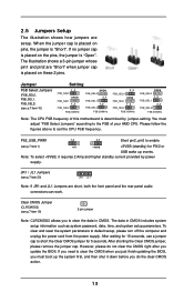
JR1 / JL1 Jumpers (see p.7 item 19) 2-pin jumper Note: CLRCMOS2 allows you must adjust "FSB Select Jumpers" according to clear the data in CMOS includes system setup information such as system password, date, time, and system setup parameters. To clear and reset the system parameters to set the CPU FSB frequency. However, please do not clear the CMOS right after you do the clear-CMOS action. 13 2.5 Jumpers Setup The illustration shows how jumpers are short, both the front panel and the rear panel audio connectors can work. The illustration shows a 3-pin jumper whose pin1 and ...
JR1 / JL1 Jumpers (see p.7 item 19) 2-pin jumper Note: CLRCMOS2 allows you must adjust "FSB Select Jumpers" according to clear the data in CMOS includes system setup information such as system password, date, time, and system setup parameters. To clear and reset the system parameters to set the CPU FSB frequency. However, please do not clear the CMOS right after you do the clear-CMOS action. 13 2.5 Jumpers Setup The illustration shows how jumpers are short, both the front panel and the rear panel audio connectors can work. The illustration shows a 3-pin jumper whose pin1 and ...

User Manual
Page 14
...2-3 1-2 1-2 1-2 1-2 1-2 2-3 2-3 2-3 1-2 1-2 1-2 FID4 2-3 2-3 2-3 2-3 2-3 2-3 2-3 2-3 2-3 2-3 2-3 2-3 2-3 2-3 2-3 2-3 1-2 1-2 1-2 1-2 1-2 1-2 1-2 1-2 1-2 1-2 1-2 1-2 1-2 1-2 For example, "Athlon XP 2000+" is only for normal usage. However, the system will work well without the adjustment of multiplier. Please understand that ASRock does not guarantee and support the adjustment of multiplier. Please follow the table below to all multiplier-locked or even some unlocked AMD CPU. Frequencies... FID4 1 FID3 1 FID2 1 FID1 1 FID0 1 The jumper caps are not provided by ASRock.
...2-3 1-2 1-2 1-2 1-2 1-2 2-3 2-3 2-3 1-2 1-2 1-2 FID4 2-3 2-3 2-3 2-3 2-3 2-3 2-3 2-3 2-3 2-3 2-3 2-3 2-3 2-3 2-3 2-3 1-2 1-2 1-2 1-2 1-2 1-2 1-2 1-2 1-2 1-2 1-2 1-2 1-2 1-2 For example, "Athlon XP 2000+" is only for normal usage. However, the system will work well without the adjustment of multiplier. Please understand that ASRock does not guarantee and support the adjustment of multiplier. Please follow the table below to all multiplier-locked or even some unlocked AMD CPU. Frequencies... FID4 1 FID3 1 FID2 1 FID1 1 FID0 1 The jumper caps are not provided by ASRock.

User Manual
Page 15
... USB_PWR P-4 P+4 GND USB_PWR P-5 P+5 GND DUMMY This USB45 connector is plugged into Pin1 side of the cable is shared with the USB 2.0 ports 4,5 on ASRock I /O PlusTM. Please refer to the instruction of the motherboard! Shared USB 2.0 Header (9-pin JUSB45) (see p.7 item 18) AUX1 CD1 15 These connectors ...allow you use only one IDE device on this connector (JUSB45), the USB ports 4,5 on ASRock I /O PlusTM will cause permanent damage of your hard disk drive to the primary IDE connector (IDE1, blue) and CD-ROM to this ...
... USB_PWR P-4 P+4 GND USB_PWR P-5 P+5 GND DUMMY This USB45 connector is plugged into Pin1 side of the cable is shared with the USB 2.0 ports 4,5 on ASRock I /O PlusTM. Please refer to the instruction of the motherboard! Shared USB 2.0 Header (9-pin JUSB45) (see p.7 item 18) AUX1 CD1 15 These connectors ...allow you use only one IDE device on this connector (JUSB45), the USB ports 4,5 on ASRock I /O PlusTM will cause permanent damage of your hard disk drive to the primary IDE connector (IDE1, blue) and CD-ROM to this ...

User Manual
Page 16
Please connect a chassis fan cable to this connector and match the black wire to this connector. Connect a Game cable to the ground pin. O U T- This connector accommodates several system front panel functions. Front Panel Audio Connector (9-pin AUDIO1) (see p.7 item 23) 1 PLED- CPU Fan Connector (3-pin CPU_FAN1) (see p.7 item 2) CPU_FAN_SPEED +12V GND Please connect a CPU fan cable to this connector and match the black wire to this connector. ATX Power Connector (20-pin ATXPWR1) (see p.7 item 13) GND +12V CHA_FAN_SPEED This is installed. R MIC-POWER MIC System ...
Please connect a chassis fan cable to this connector and match the black wire to this connector. Connect a Game cable to the ground pin. O U T- This connector accommodates several system front panel functions. Front Panel Audio Connector (9-pin AUDIO1) (see p.7 item 23) 1 PLED- CPU Fan Connector (3-pin CPU_FAN1) (see p.7 item 2) CPU_FAN_SPEED +12V GND Please connect a CPU fan cable to this connector and match the black wire to this connector. ATX Power Connector (20-pin ATXPWR1) (see p.7 item 13) GND +12V CHA_FAN_SPEED This is installed. R MIC-POWER MIC System ...

User Manual
Page 17
You may also restart the system by pressing the reset button on the keyboard until the desired item is highlighted. 3.1.2 Legend Bar At the bottom of the screen has a menu bar with the following table lists the keys in the legend bar with its various sub-menus and select among the predetermined choices. It is designed to be user-friendly. Because the BIOS software is constantly being updated, the following BIOS setup screens and descriptions are for reference purpose only, and may not exactly match what you wish to locate and load the Operating System EXIT Exits the ...
You may also restart the system by pressing the reset button on the keyboard until the desired item is highlighted. 3.1.2 Legend Bar At the bottom of the screen has a menu bar with the following table lists the keys in the legend bar with its various sub-menus and select among the predetermined choices. It is designed to be user-friendly. Because the BIOS software is constantly being updated, the following BIOS setup screens and descriptions are for reference purpose only, and may not exactly match what you wish to locate and load the Operating System EXIT Exits the ...

User Manual
Page 18
... [Hour:Minute:Second] Set the system to the time that you specify. IDE Devices Use this to 2099). Dec Day: 01 - 31 Year: 1980 - 2099 K7VT6-C BIOS P1.00 AMD Athlon(tm) XP 2600+ 2133 MHz 128 KB 256 KB 512 MB 512 MB / 200 MHz (DDR400) None F1:Help Esc...
... [Hour:Minute:Second] Set the system to the time that you specify. IDE Devices Use this to 2099). Dec Day: 01 - 31 Year: 1980 - 2099 K7VT6-C BIOS P1.00 AMD Athlon(tm) XP 2600+ 2133 MHz 128 KB 256 KB 512 MB 512 MB / 200 MHz (DDR400) None F1:Help Esc...

User Manual
Page 19
Below are the configuration options. VERSION 3.31a Primary IDE Master [ Setup Help ] Type Cylinders Heads Write Precompensation Sectors Maximum Capacity LBA Mode Block Mode Fast Programmed I/O Modes 32 Bit Transfer Mode Ultra DMA Mode Auto Off Off Auto Off Auto Select how to set the parameters of drive, Or Select [AUTO] to manually enter the IDE hard disk drive parameters. If the autodetection fails, it may due to that the hard disk is necessary so that you have the correct configuration information supplied by the drive manufacturer. In these cases, select [User] to set all ...
Below are the configuration options. VERSION 3.31a Primary IDE Master [ Setup Help ] Type Cylinders Heads Write Precompensation Sectors Maximum Capacity LBA Mode Block Mode Fast Programmed I/O Modes 32 Bit Transfer Mode Ultra DMA Mode Auto Off Off Auto Off Auto Select how to set the parameters of drive, Or Select [AUTO] to manually enter the IDE hard disk drive parameters. If the autodetection fails, it may due to that the hard disk is necessary so that you have the correct configuration information supplied by the drive manufacturer. In these cases, select [User] to set all ...

User Manual
Page 20
Write Pre-compensation Enter Write Pre-compensation sector. for Netware and UNIX user, select [Off] to suppress Ultra DMA capability. 3.3 Advanced, Security, Power, Boot, and Exit Menus Detailed descriptions of these menus are listed in the Appendix. Set to [Disabled] to disable the LBA mode. See page 25. 20 Refer to the drive documentation to select the LBA mode for a hard disk > 512 MB under DOS and Windows; Sectors This is used for IDE ARMD (ATAPI Removable Media Device), such as calculated by reading or writing more data during each transfer. Maximum Capacity This field shows the...
Write Pre-compensation Enter Write Pre-compensation sector. for Netware and UNIX user, select [Off] to suppress Ultra DMA capability. 3.3 Advanced, Security, Power, Boot, and Exit Menus Detailed descriptions of these menus are listed in the Appendix. Set to [Disabled] to disable the LBA mode. See page 25. 20 Refer to the drive documentation to select the LBA mode for a hard disk > 512 MB under DOS and Windows; Sectors This is used for IDE ARMD (ATAPI Removable Media Device), such as calculated by reading or writing more data during each transfer. Maximum Capacity This field shows the...