User Manual
Page 3
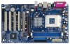
... 3.2 Main Menu 18 3.3 Advanced, Security, Power, Boot, and Exit Menus 20 4. Boot Setup Menu 29 5. Power Setup Menu 28 4. Contents 1. Introduction 4 1.1 Package Contents 4 1.2 Specifications 5 1.3 Motherboard Layout 7 1.4 ASRock I/O Plus 8 TM ...2. Software Support 21 4.1 Install Operating System 21 4.2 Support CD Information 21 4.2.1 Running Support CD 21 4.2.2 Drivers Menu 21 4.2.3 Utilities Menu 21 4.2.4 Contact Information...
... 3.2 Main Menu 18 3.3 Advanced, Security, Power, Boot, and Exit Menus 20 4. Boot Setup Menu 29 5. Power Setup Menu 28 4. Contents 1. Introduction 4 1.1 Package Contents 4 1.2 Specifications 5 1.3 Motherboard Layout 7 1.4 ASRock I/O Plus 8 TM ...2. Software Support 21 4.1 Install Operating System 21 4.2 Support CD Information 21 4.2.1 Running Support CD 21 4.2.2 Drivers Menu 21 4.2.3 Utilities Menu 21 4.2.4 Contact Information...

User Manual
Page 4
... to change without further notice. Chapter 3 and 4 contain basic BIOS setup and support CD information. ASRock website http://www.asrock.com 1.1 Package Contents 1 x ASRock K7VT6-C Motherboard (ATX Form Factor: 12.0-in x 7.0-in, 30.5 cm x 17.8 cm) 1 x ASRock K7VT6-C Quick Installation Guide 1 x ASRock K7VT6-C Support CD 1 x Ultra ATA 66/100/133 IDE Ribbon Cable (80-conductor) 1 x 3.5-in Appendix on page...
... to change without further notice. Chapter 3 and 4 contain basic BIOS setup and support CD information. ASRock website http://www.asrock.com 1.1 Package Contents 1 x ASRock K7VT6-C Motherboard (ATX Form Factor: 12.0-in x 7.0-in, 30.5 cm x 17.8 cm) 1 x ASRock K7VT6-C Quick Installation Guide 1 x ASRock K7VT6-C Support CD 1 x Ultra ATA 66/100/133 IDE Ribbon Cable (80-conductor) 1 x 3.5-in Appendix on page...

User Manual
Page 5
...97 Audio LAN: Speed: 802.3u (10/100 Ethernet), Supports Wake-On-LAN Hardware Monitor: CPU Temperature Sensing Motherboard Temperature Sensing CPU Overheat Shutdown to Protect CPU Life (ASRock U-COP)(see CAUTION 1) CPU Fan Tachometer Chassis Fan Tachometer Voltage Monitoring: +12V, +5V, +3.3V, Vcore ... 1.5V, 8X/4X AGP Card (see CAUTION 2) USB 2.0: 6 USB 2.0 ports: include 6 ready-to-use USB 2.0 ports on the rear panel, (see CAUTION 3) ASRock I/O PlusTM: 1 PS/2 Mouse Port, 1 PS/2 Keyboard Port, 1 Serial Port: COM1, 1 Parallel Port (ECP/EPP Support) 6 ready-to-use USB 2.0 Ports, ...
...97 Audio LAN: Speed: 802.3u (10/100 Ethernet), Supports Wake-On-LAN Hardware Monitor: CPU Temperature Sensing Motherboard Temperature Sensing CPU Overheat Shutdown to Protect CPU Life (ASRock U-COP)(see CAUTION 1) CPU Fan Tachometer Chassis Fan Tachometer Voltage Monitoring: +12V, +5V, +3.3V, Vcore ... 1.5V, 8X/4X AGP Card (see CAUTION 2) USB 2.0: 6 USB 2.0 ports: include 6 ready-to-use USB 2.0 ports on the rear panel, (see CAUTION 3) ASRock I/O PlusTM: 1 PS/2 Mouse Port, 1 PS/2 Keyboard Port, 1 Serial Port: COM1, 1 Parallel Port (ECP/EPP Support) 6 ready-to-use USB 2.0 Ports, ...

User Manual
Page 6
...not recommended to perform over clocking. Before you resume the system, please check if the CPU fan on the AGP slot of this motherboard! Although this motherboard is determined by jumper-setting. You must adjust "FSB Select Jumpers" according to spray thermal grease between the CPU and the heatsink ... See page 13 for USB 2.0 works fine under Microsoft® Windows® 98/ME. 4. Do NOT use a 3.3V AGP card on the motherboard functions properly and unplug the power cord, then plug it is detected, the system will automatically shutdown. Power Management for the details of "FSB Select...
...not recommended to perform over clocking. Before you resume the system, please check if the CPU fan on the AGP slot of this motherboard! Although this motherboard is determined by jumper-setting. You must adjust "FSB Select Jumpers" according to spray thermal grease between the CPU and the heatsink ... See page 13 for USB 2.0 works fine under Microsoft® Windows® 98/ME. 4. Do NOT use a 3.3V AGP card on the motherboard functions properly and unplug the power cord, then plug it is detected, the system will automatically shutdown. Power Management for the details of "FSB Select...

User Manual
Page 7
1.3 Motherboard Layout 1 2 34 5 6 17.8cm (7.0 in) PS/2 MOUSE PS/2 KEYBOARD PS2_USB_PWR1 1 FID4 FID3 FID2 FID1 FID0 J1 CPU_FAN1 1 1 1 1 1 SOCKET 462 SERIAL PORT (COM1) PARALLEL PORT DDR 1 (... B: USB1 IDE1 IDE2 25 USB 2.0 T: USB4 1 B: USB5 JUSB45 VIA KT600 CHIPSET Top: Line In Center: Line Out Bottom: Mic In 7 24 2Mb 8 BIOS FSB 400 K7VT6-C 23 22 21 20 19 LAN PHY GAME1 1 SUPER I/O AGP 8X 1.5V_AGP1 PCI1 DDR400 PCI2 1 FSB_SEL0 1 FSB_SEL1 1 FSB_SEL2 1 AUDIO1 JR1 JL1 CMOS BATTERY AUDIO CODEC...
1.3 Motherboard Layout 1 2 34 5 6 17.8cm (7.0 in) PS/2 MOUSE PS/2 KEYBOARD PS2_USB_PWR1 1 FID4 FID3 FID2 FID1 FID0 J1 CPU_FAN1 1 1 1 1 1 SOCKET 462 SERIAL PORT (COM1) PARALLEL PORT DDR 1 (... B: USB1 IDE1 IDE2 25 USB 2.0 T: USB4 1 B: USB5 JUSB45 VIA KT600 CHIPSET Top: Line In Center: Line Out Bottom: Mic In 7 24 2Mb 8 BIOS FSB 400 K7VT6-C 23 22 21 20 19 LAN PHY GAME1 1 SUPER I/O AGP 8X 1.5V_AGP1 PCI1 DDR400 PCI2 1 FSB_SEL0 1 FSB_SEL1 1 FSB_SEL2 1 AUDIO1 JR1 JL1 CMOS BATTERY AUDIO CODEC...

User Manual
Page 9
...edges and do not over-tighten the screws! Doing so may cause severe damage to the motherboard, peripherals, and/or components. 1. Installation K7VT6-C is detached from the wall socket before touching any motherboard settings. Failure to static electricity, NEVER place your chassis to the chassis, please do .... 3. Whenever you install or remove any component, place it . Before you uninstall any component, ensure that the motherboard fits into the screw holes to secure the motherboard to ensure that the power is switched off or the power cord is an ATX form factor (12.0-in x ...
...edges and do not over-tighten the screws! Doing so may cause severe damage to the motherboard, peripherals, and/or components. 1. Installation K7VT6-C is detached from the wall socket before touching any motherboard settings. Failure to static electricity, NEVER place your chassis to the chassis, please do .... 3. Whenever you install or remove any component, place it . Before you uninstall any component, ensure that the motherboard fits into the screw holes to secure the motherboard to ensure that the power is switched off or the power cord is an ATX form factor (12.0-in x ...

User Manual
Page 11
... orientation. Step 3. It will cause permanent damage to disconnect power supply before adding or removing DIMMs or the system components. Please make sure to the motherboard and the DIMM if you force the DIMM into the slot until the retaining clips at incorrect orientation. Step 1. Unlock a DIMM slot by pressing the... retaining clips outward. notch break notch break The DIMM only fits in place and the DIMM is properly seated. 11 2.3 Installation of Memory Modules (DIMM) K7VT6-C motherboard provides two 184-pin DDR (Double Data Rate) DIMM slots.
... orientation. Step 3. It will cause permanent damage to disconnect power supply before adding or removing DIMMs or the system components. Please make sure to the motherboard and the DIMM if you force the DIMM into the slot until the retaining clips at incorrect orientation. Step 1. Unlock a DIMM slot by pressing the... retaining clips outward. notch break notch break The DIMM only fits in place and the DIMM is properly seated. 11 2.3 Installation of Memory Modules (DIMM) K7VT6-C motherboard provides two 184-pin DDR (Double Data Rate) DIMM slots.

User Manual
Page 12
... and 1 AGP slot on K7VT6-C motherboard. Please read the documentation of your motherboard is unplugged. Step 2. Remove the system unit cover (if your graphics card, please check with screws. Keep the screws for the card before you intend to install a graphics card. The ASRock AGP slot has a special ...design of this motherboard! Please do NOT use . Step 4. For the voltage information of the expansion card and make sure that the ...
... and 1 AGP slot on K7VT6-C motherboard. Please read the documentation of your motherboard is unplugged. Step 2. Remove the system unit cover (if your graphics card, please check with screws. Keep the screws for the card before you intend to install a graphics card. The ASRock AGP slot has a special ...design of this motherboard! Please do NOT use . Step 4. For the voltage information of the expansion card and make sure that the ...
User Manual
Page 13
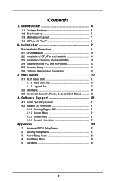
... set the CPU FSB frequency. If you need to clear the CMOS when you just finish updating the BIOS, you to the FSB of this motherboard is "Short". Jumper FSB Select Jumpers (FSB_SEL0, FSB_SEL1, FSB_SEL2) (see p.7 item 19) 2-pin jumper Note: CLRCMOS2 allows you must adjust "FSB Select Jumpers" according to...
... set the CPU FSB frequency. If you need to clear the CMOS when you just finish updating the BIOS, you to the FSB of this motherboard is "Short". Jumper FSB Select Jumpers (FSB_SEL0, FSB_SEL1, FSB_SEL2) (see p.7 item 19) 2-pin jumper Note: CLRCMOS2 allows you must adjust "FSB Select Jumpers" according to...

User Manual
Page 15
...be able to the secondary IDE connector (IDE2, black). When using the front panel USB ports by attaching the front panel USB cable to this motherboard, please set the IDE device as a CDROM, DVD-ROM, TV tuner card, or MPEG card. Besides, to optimize compatibility and performance, ... of the cable is shared with the USB 2.0 ports 4,5 on this connector (JUSB45), the USB ports 4,5 on ASRock I /O PlusTM. Please refer to Pin1 Note: Make sure the red-striped side of the motherboard! Internal Audio Connectors (4-pin CD1, 4-pin AUX1) (CD1: see p.7 item 17) AUX-R GND GND AUX-L CD...
...be able to the secondary IDE connector (IDE2, black). When using the front panel USB ports by attaching the front panel USB cable to this motherboard, please set the IDE device as a CDROM, DVD-ROM, TV tuner card, or MPEG card. Besides, to optimize compatibility and performance, ... of the cable is shared with the USB 2.0 ports 4,5 on this connector (JUSB45), the USB ports 4,5 on ASRock I /O PlusTM. Please refer to Pin1 Note: Make sure the red-striped side of the motherboard! Internal Audio Connectors (4-pin CD1, 4-pin AUX1) (CD1: see p.7 item 17) AUX-R GND GND AUX-L CD...

User Manual
Page 17
...-Test (POST) to enter the BIOS Setup after POST, restart the system by pressing + + , or by turning the system off and then back on the motherboard stores the BIOS Setup Utility. If you to be user-friendly. The Flash Memory on . You may also restart the system by pressing the reset...
...-Test (POST) to enter the BIOS Setup after POST, restart the system by pressing + + , or by turning the system off and then back on the motherboard stores the BIOS Setup Utility. If you to be user-friendly. The Flash Memory on . You may also restart the system by pressing the reset...

User Manual
Page 21
...your dealer for further information. 21 or you need to contact ASRock or want to know more information. 4.2 Support CD Information The Support CD that came with the motherboard contains necessary drivers and useful utilities that the motherboard supports. 4. Click on the file ASSETUP.EXE from the ...® Windows® operating systems: 98 SE / ME / 2000 / XP. Because motherboard settings and hardware options vary, use the setup procedures in the Support CD to visit ASRock's website at http://www.asrock.com; If the Main Menu did not appear automatically, locate and double click on a...
...your dealer for further information. 21 or you need to contact ASRock or want to know more information. 4.2 Support CD Information The Support CD that came with the motherboard contains necessary drivers and useful utilities that the motherboard supports. 4. Click on the file ASSETUP.EXE from the ...® Windows® operating systems: 98 SE / ME / 2000 / XP. Because motherboard settings and hardware options vary, use the setup procedures in the Support CD to visit ASRock's website at http://www.asrock.com; If the Main Menu did not appear automatically, locate and double click on a...

User Manual
Page 22
DRAM Frequency If set to [Auto], the motherboard will allow better tolerance for memory compatibility when it is set to [Enabled]. 22 You may cause ...," "Security," "Power," "Boot," and "Exit." 1. Appendix: Advanced BIOS Setup This section will let the CPU host frequency of this motherboard determined by the jumper-setting, you must set the FSB jumper adjustment according to your AMD CPU before you thoroughly know the feature. Advanced...because the CPU host frequency of spread spectrum. Boot Failure Guard Enable or disable the feature of this motherboard is [Disabled].
DRAM Frequency If set to [Auto], the motherboard will allow better tolerance for memory compatibility when it is set to [Enabled]. 22 You may cause ...," "Security," "Power," "Boot," and "Exit." 1. Appendix: Advanced BIOS Setup This section will let the CPU host frequency of this motherboard determined by the jumper-setting, you must set the FSB jumper adjustment according to your AMD CPU before you thoroughly know the feature. Advanced...because the CPU host frequency of spread spectrum. Boot Failure Guard Enable or disable the feature of this motherboard is [Disabled].

User Manual
Page 26
... allows you to monitor the parameters for the onboard AC'97 Audio feature. OnBoard AC'97 Audio Select [Disabled], [Auto] or [Enabled] for CPU temperature, Motherboard temperature, CPU fan speed, and critical voltage. System Hardware Monitor You may check the status of the hardware on your system.
... allows you to monitor the parameters for the onboard AC'97 Audio feature. OnBoard AC'97 Audio Select [Disabled], [Auto] or [Enabled] for CPU temperature, Motherboard temperature, CPU fan speed, and critical voltage. System Hardware Monitor You may check the status of the hardware on your system.

Quick Installation Guide
Page 1
... of such damages arising from any defect or error in the guide or product. All rights reserved. 1 ASRock K7VT6-C Motherboard English With respect to the contents of this guide, ASRock does not provide warranty of any kind, either expressed or implied, including but not limited to infringe. Copyright... transcribed, transmitted, or translated in any language, in any form or by any means, except duplication of documentation by ASRock. Disclaimer: Specifications and information contained in this guide are used only for informational use only and subject to change without written consent ...
... of such damages arising from any defect or error in the guide or product. All rights reserved. 1 ASRock K7VT6-C Motherboard English With respect to the contents of this guide, ASRock does not provide warranty of any kind, either expressed or implied, including but not limited to infringe. Copyright... transcribed, transmitted, or translated in any language, in any form or by any means, except duplication of documentation by ASRock. Disclaimer: Specifications and information contained in this guide are used only for informational use only and subject to change without written consent ...

Quick Installation Guide
Page 2
Motherboard Layout English 1 PS2_USB_PWR1 Jumper 2 CPU Fan Connector (CPU_FAN1) 3 CPU Socket 4 North Bridge Controller 5 184-pin DDR DIMM Slots (DDR1- 2) 6 ATX Power Connector (ATXPWR1) 7 Secondary IDE ... PCI Slots (PCI1- 5) 23 Game Port Connector (GAME1) 24 Flash Memory 25 Shared USB 2.0 Header (JUSB45, Blue) 26 J1 Jumper (FID0, FID1, FID2, FID3, FID4) 2 ASRock K7VT6-C Motherboard
Motherboard Layout English 1 PS2_USB_PWR1 Jumper 2 CPU Fan Connector (CPU_FAN1) 3 CPU Socket 4 North Bridge Controller 5 184-pin DDR DIMM Slots (DDR1- 2) 6 ATX Power Connector (ATXPWR1) 7 Secondary IDE ... PCI Slots (PCI1- 5) 23 Game Port Connector (GAME1) 24 Flash Memory 25 Shared USB 2.0 Header (JUSB45, Blue) 26 J1 Jumper (FID0, FID1, FID2, FID3, FID4) 2 ASRock K7VT6-C Motherboard

Quick Installation Guide
Page 3
ASRock I/O PlusTM 1 Parallel Port 2 RJ-45 Port 3 Line In (Light Blue) 4 Line Out (Lime) 5 Microphone (Pink) 6 2 x Shared USB 2.0 Port (USB4, USB5) 7 2 x USB 2.0 Port (USB0, USB1) 8 2 x USB 2.0 Port (USB2, USB3) 9 Serial Port: COM1 10 PS/2 Keyboard Port (Purple) 11 PS/2 Mouse Port (Green) English 3 ASRock K7VT6-C Motherboard
ASRock I/O PlusTM 1 Parallel Port 2 RJ-45 Port 3 Line In (Light Blue) 4 Line Out (Lime) 5 Microphone (Pink) 6 2 x Shared USB 2.0 Port (USB4, USB5) 7 2 x USB 2.0 Port (USB0, USB1) 8 2 x USB 2.0 Port (USB2, USB3) 9 Serial Port: COM1 10 PS/2 Keyboard Port (Purple) 11 PS/2 Mouse Port (Green) English 3 ASRock K7VT6-C Motherboard

Quick Installation Guide
Page 4
... in Floppy Drive Ribbon Cable 1 x ASRock I/O PlusTM Shield 4 ASRock K7VT6-C Motherboard English Because the motherboard specifications and the BIOS software might be updated, the content of the motherboard and step-bystep installation guide. 1. ASRock website http://www.asrock.com 1.1 Package Contents 1 x ASRock K7VT6-C Motherboard (ATX Form Factor: 12.0-in x 7.0-in, 30.5 cm x 17.8 cm) 1 x ASRock K7VT6-C Quick Installation Guide 1 x ASRock K7VT6-C Support CD 1 x Ultra ATA...
... in Floppy Drive Ribbon Cable 1 x ASRock I/O PlusTM Shield 4 ASRock K7VT6-C Motherboard English Because the motherboard specifications and the BIOS software might be updated, the content of the motherboard and step-bystep installation guide. 1. ASRock website http://www.asrock.com 1.1 Package Contents 1 x ASRock K7VT6-C Motherboard (ATX Form Factor: 12.0-in x 7.0-in, 30.5 cm x 17.8 cm) 1 x ASRock K7VT6-C Quick Installation Guide 1 x ASRock K7VT6-C Support CD 1 x Ultra ATA...

Quick Installation Guide
Page 5
...LAN: Speed: 802.3u (10/100 Ethernet), Supports Wake-On-LAN Hardware Monitor: CPU Temperature Sensing Motherboard Temperature Sensing CPU Overheat Shutdown to Protect CPU Life (ASRock U-COP)(see CAUTION 1) CPU Fan Tachometer Chassis Fan Tachometer Voltage Monitoring: +12V, +5V, +3.3V...-to-use USB 2.0 ports on the rear panel, (see CAUTION 3) ASRock I/O PlusTM: 1 PS/2 Mouse Port, 1 PS/2 Keyboard Port, 1 Serial Port: COM1, 1 Parallel Port (ECP/EPP Support) 6 ready-to-use USB 2.0 Ports, 1 RJ-45 Port, Audio Jack: Line In / Line Out / Microphone English 5 ASRock K7VT6-C Motherboard
...LAN: Speed: 802.3u (10/100 Ethernet), Supports Wake-On-LAN Hardware Monitor: CPU Temperature Sensing Motherboard Temperature Sensing CPU Overheat Shutdown to Protect CPU Life (ASRock U-COP)(see CAUTION 1) CPU Fan Tachometer Chassis Fan Tachometer Voltage Monitoring: +12V, +5V, +3.3V...-to-use USB 2.0 ports on the rear panel, (see CAUTION 3) ASRock I/O PlusTM: 1 PS/2 Mouse Port, 1 PS/2 Keyboard Port, 1 Serial Port: COM1, 1 Parallel Port (ECP/EPP Support) 6 ready-to-use USB 2.0 Ports, 1 RJ-45 Port, Audio Jack: Line In / Line Out / Microphone English 5 ASRock K7VT6-C Motherboard

Quick Installation Guide
Page 6
... SP1/2000 SP4. See page 9 for "CPU Host Frequency" configuration. It may cause the instability of this motherboard is determined by jumper-setting. The CPU host frequency of "User Manual" in BIOS. English 6 ASRock K7VT6-C Motherboard It may cause permanent damage! 3. You must adjust "FSB Select Jumpers" according to the FSB of your AMD...
... SP1/2000 SP4. See page 9 for "CPU Host Frequency" configuration. It may cause the instability of this motherboard is determined by jumper-setting. The CPU host frequency of "User Manual" in BIOS. English 6 ASRock K7VT6-C Motherboard It may cause permanent damage! 3. You must adjust "FSB Select Jumpers" according to the FSB of your AMD...

