RAID Installation Guide
Page 2
... disk. 2 STEP 4: Connect the other end of the SATA data cable to install the SATA hard disks. STEP 2: Connect the SATA power cable to the motherboard's SATA connector. STEP 1: Install the SATA hard disks into the drive bays of the SATA data cable to the SATA hard disk. STEP 3: Connect one... end of your chassis. 1. Guide to SATA Hard Disks Installation 1.1 Serial ATA (SATA) Hard Disks Installation This motherboard adopts VIA VT8237 southbridge chipset that supports Serial ATA (SATA) hard disks. You may install SATA hard disks on this...
... disk. 2 STEP 4: Connect the other end of the SATA data cable to install the SATA hard disks. STEP 2: Connect the SATA power cable to the motherboard's SATA connector. STEP 1: Install the SATA hard disks into the drive bays of the SATA data cable to the SATA hard disk. STEP 3: Connect one... end of your chassis. 1. Guide to SATA Hard Disks Installation 1.1 Serial ATA (SATA) Hard Disks Installation This motherboard adopts VIA VT8237 southbridge chipset that supports Serial ATA (SATA) hard disks. You may install SATA hard disks on this...
RAID Installation Guide
Page 4
... not provide any HDDs of the same model and capacity when creating a RAID set. RAID The term "RAID" stands for "Redundant Array of RAID This motherboard adopts VIA VT8237 south bridge chipset that optimizes two identical hard disk drives to configure RAID 0, RAID 1, and JBOD settings. It will introduce the basic...
... not provide any HDDs of the same model and capacity when creating a RAID set. RAID The term "RAID" stands for "Redundant Array of RAID This motherboard adopts VIA VT8237 south bridge chipset that optimizes two identical hard disk drives to configure RAID 0, RAID 1, and JBOD settings. It will introduce the basic...
User Manual
Page 1
MOTHERBOARD K7VT4A Pro User Manual Version 1.1 Published September 2004 Copyright©2004 ASRock INC. All rights reserved. 1
MOTHERBOARD K7VT4A Pro User Manual Version 1.1 Published September 2004 Copyright©2004 ASRock INC. All rights reserved. 1

User Manual
Page 3
Introduction 4 1.1 Package Contents 4 1.2 Specifications 5 1.3 Motherboard Layout 7 1.4 ASRock I/O Plus 8 TM ...2. Boot Setup Menu 32 5. Software Support 24 4.1 Install Operating System 24 4.2 Support CD Information 24 4.2.1 Running Support CD 24 4.2.2 Drivers Menu 24 4.2.3 Utilities ...
Introduction 4 1.1 Package Contents 4 1.2 Specifications 5 1.3 Motherboard Layout 7 1.4 ASRock I/O Plus 8 TM ...2. Boot Setup Menu 32 5. Software Support 24 4.1 Install Operating System 24 4.2 Support CD Information 24 4.2.1 Running Support CD 24 4.2.2 Drivers Menu 24 4.2.3 Utilities ...
User Manual
Page 4
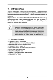
... support lists on ASRock website without notice. ASRock website http://www.asrock.com 1.1 Package Contents 1 x ASRock K7VT4A Pro Motherboard (ATX Form Factor: 12.0-in x 7.0-in, 30.5 cm x 17.8 cm) 1 x ASRock K7VT4A Pro Quick Installation Guide 1 x ASRock K7VT4A Pro Support CD 1 x Ultra ATA 66/100/133 IDE Ribbon Cable (80-conductor) 1 x 3.5-in Appendix on page 25 for purchasing ASRock K7VT4A Pro motherboard, a reliable motherboard produced under ASRock's consistently stringent quality...
... support lists on ASRock website without notice. ASRock website http://www.asrock.com 1.1 Package Contents 1 x ASRock K7VT4A Pro Motherboard (ATX Form Factor: 12.0-in x 7.0-in, 30.5 cm x 17.8 cm) 1 x ASRock K7VT4A Pro Quick Installation Guide 1 x ASRock K7VT4A Pro Support CD 1 x Ultra ATA 66/100/133 IDE Ribbon Cable (80-conductor) 1 x 3.5-in Appendix on page 25 for purchasing ASRock K7VT4A Pro motherboard, a reliable motherboard produced under ASRock's consistently stringent quality...

User Manual
Page 5
... Audio LAN: Speed: 802.3u (10/100 Ethernet), Supports Wake-On-LAN Hardware Monitor: CPU Temperature Sensing Motherboard Temperature Sensing CPU Overheat Shutdown to Protect CPU Life (ASRock U-COP)(see CAUTION 1) CPU Fan Tachometer Chassis Fan Tachometer Voltage Monitoring: +12V, +5V, +3.3V, Vcore... USB 2.0 ports: include 6 ready-to-use USB 2.0 ports on the rear panel, plus one on-board header supporting 2 extra USB 2.0 ports (see CAUTION 3) ASRock I/O PlusTM: 1 PS/2 Mouse Port, 1 PS/2 Keyboard Port, 1 Serial Port: COM1, 1 Parallel Port (ECP/EPP Support) 6 ready-to-use USB 2.0 ...
... Audio LAN: Speed: 802.3u (10/100 Ethernet), Supports Wake-On-LAN Hardware Monitor: CPU Temperature Sensing Motherboard Temperature Sensing CPU Overheat Shutdown to Protect CPU Life (ASRock U-COP)(see CAUTION 1) CPU Fan Tachometer Chassis Fan Tachometer Voltage Monitoring: +12V, +5V, +3.3V, Vcore... USB 2.0 ports: include 6 ready-to-use USB 2.0 ports on the rear panel, plus one on-board header supporting 2 extra USB 2.0 ports (see CAUTION 3) ASRock I/O PlusTM: 1 PS/2 Mouse Port, 1 PS/2 Keyboard Port, 1 Serial Port: COM1, 1 Parallel Port (ECP/EPP Support) 6 ready-to-use USB 2.0 ...

User Manual
Page 6
... Frequency" configuration as "Manual" in the Support CD for the details of "FSB Select Jumpers" adjustment, and page 25 of this motherboard is not recommended to Microsoft® official document at http://www.microsoft.com/whdc/hwdev/bus/USB/USB2support.mspx 4. See page 13 for... "CPU Host Frequency" configuration. 6 To improve heat dissipation, remember to the FSB of this motherboard! Power Management for advanced users' reference, see CAUTION 4) Microsoft® Windows® 98 SE / ME / 2000 / XP Compliant CAUTION! 1. ...
... Frequency" configuration as "Manual" in the Support CD for the details of "FSB Select Jumpers" adjustment, and page 25 of this motherboard is not recommended to Microsoft® official document at http://www.microsoft.com/whdc/hwdev/bus/USB/USB2support.mspx 4. See page 13 for... "CPU Host Frequency" configuration. 6 To improve heat dissipation, remember to the FSB of this motherboard! Power Management for advanced users' reference, see CAUTION 4) Microsoft® Windows® 98 SE / ME / 2000 / XP Compliant CAUTION! 1. ...

User Manual
Page 7
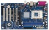
1.3 Motherboard Layout 1 2 34 5 6 17.8cm (7.0 in) PS/2 MOUSE PS/2 KEYBOARD PS2_USB_PWR1 1 FID4 FID3 FID2 FID1 FID0 J1 CPU_FAN1 1 1 1 1 1 SOCKET 462 SERIAL PORT (COM1) PARALLEL PORT DDR 1 (... Top: RJ-45 B: USB1 USB 2.0 T: USB4 1 B: USB5 JUSB45 VIA KT400A CHIPSET Top: Line In Center: Line Out Bottom: Mic In 27 2MB BIOS AGP 8X K7VT4A PRO LAN PHY SUPER I/O 1.5V_AGP1 IDE1 IDE2 7 8 9 26 25 24 23 22 GAME1 1 DDR400 PCI1 PCI2 1 FSB_SEL0 1 FSB_SEL1 1 FSB_SEL2 1 AUDIO1 JR1 JL1 CMOS BATTERY USB2.0 1 CLRCMOS2...
1.3 Motherboard Layout 1 2 34 5 6 17.8cm (7.0 in) PS/2 MOUSE PS/2 KEYBOARD PS2_USB_PWR1 1 FID4 FID3 FID2 FID1 FID0 J1 CPU_FAN1 1 1 1 1 1 SOCKET 462 SERIAL PORT (COM1) PARALLEL PORT DDR 1 (... Top: RJ-45 B: USB1 USB 2.0 T: USB4 1 B: USB5 JUSB45 VIA KT400A CHIPSET Top: Line In Center: Line Out Bottom: Mic In 27 2MB BIOS AGP 8X K7VT4A PRO LAN PHY SUPER I/O 1.5V_AGP1 IDE1 IDE2 7 8 9 26 25 24 23 22 GAME1 1 DDR400 PCI1 PCI2 1 FSB_SEL0 1 FSB_SEL1 1 FSB_SEL2 1 AUDIO1 JR1 JL1 CMOS BATTERY USB2.0 1 CLRCMOS2...

User Manual
Page 9
...from the power supply. Whenever you install or remove any component. 2. Before you uninstall any motherboard settings. When placing screws into it on the carpet or the like. Installation K7VT4A Pro is detached from the wall socket before touching any component, ensure that the power is switched... off or the power cord is an ATX form factor (12.0-in x 7.0-in the bag that the motherboard fits into the screw holes to...
...from the power supply. Whenever you install or remove any component. 2. Before you uninstall any motherboard settings. When placing screws into it on the carpet or the like. Installation K7VT4A Pro is detached from the wall socket before touching any component, ensure that the power is switched... off or the power cord is an ATX form factor (12.0-in x 7.0-in the bag that the motherboard fits into the screw holes to...

User Manual
Page 11
... at incorrect orientation. Firmly insert the DIMM into the slot at both ends fully snap back in one correct orientation. 2.3 Installation of Memory Modules (DIMM) K7VT4A Pro motherboard provides two 184-pin DDR (Double Data Rate) DIMM slots. Align a DIMM on the slot such that the notch on the DIMM matches the break...
... at incorrect orientation. Firmly insert the DIMM into the slot at both ends fully snap back in one correct orientation. 2.3 Installation of Memory Modules (DIMM) K7VT4A Pro motherboard provides two 184-pin DDR (Double Data Rate) DIMM slots. Align a DIMM on the slot such that the notch on the DIMM matches the break...

User Manual
Page 12
... card is used to use. Step 5. The ASRock AGP slot has a special design of this motherboard! Please do NOT use . Step 3. Step 6. Replace the system cover. 12 PCI slots: PCI slots are 5 PCI slots and 1 AGP slot on K7VT4A Pro motherboard. Keep the screws for the card before you... intend to install expansion cards that have the 32-bit PCI interface. Installing an expansion card Step 1. Please read the documentation of your motherboard is unplugged. Remove the system unit cover (...
... card is used to use. Step 5. The ASRock AGP slot has a special design of this motherboard! Please do NOT use . Step 3. Step 6. Replace the system cover. 12 PCI slots: PCI slots are 5 PCI slots and 1 AGP slot on K7VT4A Pro motherboard. Keep the screws for the card before you... intend to install expansion cards that have the 32-bit PCI interface. Installing an expansion card Step 1. Please read the documentation of your motherboard is unplugged. Remove the system unit cover (...

User Manual
Page 13
... select +5VSB, it down before you do not clear the CMOS right after you must adjust "FSB Select Jumpers" according to the FSB of this motherboard is "Short". You must boot up events. JR1 / JL1 Jumpers (see p.7 item 22) 2-pin jumper Note: CLRCMOS2 allows you need to short the Clear CMOS...
... select +5VSB, it down before you do not clear the CMOS right after you must adjust "FSB Select Jumpers" according to the FSB of this motherboard is "Short". You must boot up events. JR1 / JL1 Jumpers (see p.7 item 22) 2-pin jumper Note: CLRCMOS2 allows you need to short the Clear CMOS...

User Manual
Page 15
... ATA (SATA) Data Cable Either end of the connector. Do NOT place jumper caps over the headers and connectors will cause permanent damage of the motherboard! • Floppy Connector (33-pin FLOPPY1) (see p.7 No. 19) Pin1 FLOPPY1 the red-striped side to Pin1 Note: Make sure the red-striped side of... cable can be connected to the IDE devices 80-conductor ATA 66/100/133 cable Note: If you use only one IDE device on the motherboard. 15 Primary IDE Connector (Blue) Secondary IDE Connector (Black) (39-pin IDE1, see p.7 No. 8) (39-pin IDE2, see p.7 No. 13) SATA2 SATA1 These two ...
... ATA (SATA) Data Cable Either end of the connector. Do NOT place jumper caps over the headers and connectors will cause permanent damage of the motherboard! • Floppy Connector (33-pin FLOPPY1) (see p.7 No. 19) Pin1 FLOPPY1 the red-striped side to Pin1 Note: Make sure the red-striped side of... cable can be connected to the IDE devices 80-conductor ATA 66/100/133 cable Note: If you use only one IDE device on the motherboard. 15 Primary IDE Connector (Blue) Secondary IDE Connector (Black) (39-pin IDE1, see p.7 No. 8) (39-pin IDE2, see p.7 No. 13) SATA2 SATA1 These two ...
User Manual
Page 18
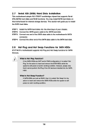
...while the system is called "Hot Swap" for the action to the SATA hard disk. 2.8 Hot Plug and Hot Swap Functions for SATA HDDs K7VT4A Pro motherboard supports Hot Plug and Hot Swap functions for SATA Devices. However, please note that supports Serial ATA (SATA) hard disks and RAID functions. ...hard disks. What is Hot Swap Function? If SATA HDDs are NOT set for RAID configuration, it is still power-on this motherboard for the action to the motherboard's SATA connector. STEP 1: Install the SATA hard disks into the SATA HDD. STEP 3: Connect one end of your chassis. ...
...while the system is called "Hot Swap" for the action to the SATA hard disk. 2.8 Hot Plug and Hot Swap Functions for SATA HDDs K7VT4A Pro motherboard supports Hot Plug and Hot Swap functions for SATA Devices. However, please note that supports Serial ATA (SATA) hard disks and RAID functions. ...hard disks. What is Hot Swap Function? If SATA HDDs are NOT set for RAID configuration, it is still power-on this motherboard for the action to the motherboard's SATA connector. STEP 1: Install the SATA hard disks into the SATA HDD. STEP 3: Connect one end of your chassis. ...

User Manual
Page 20
... is designed to enter the BIOS Setup after POST, restart the system by pressing + + , or by turning the system off and then back on the motherboard stores the BIOS Setup Utility. The following BIOS setup screens and descriptions are for reference purpose only, and may run the BIOS Setup when you...
... is designed to enter the BIOS Setup after POST, restart the system by pressing + + , or by turning the system off and then back on the motherboard stores the BIOS Setup Utility. The following BIOS setup screens and descriptions are for reference purpose only, and may run the BIOS Setup when you...

User Manual
Page 24
... more information. 4.2 Support CD Information The Support CD that came with the motherboard contains necessary drivers and useful utilities that the motherboard supports. Refer to visit ASRock's website at http://www.asrock.com; If the Main Menu did not appear automatically, locate and double click...to display the menus. 4.2.2 Drivers Menu The Drivers Menu shows the available devices drivers if the system detects installed devices. Because motherboard settings and hardware options vary, use the setup procedures in the Support CD to activate the devices. 4.2.3 Utilities Menu The Utilities...
... more information. 4.2 Support CD Information The Support CD that came with the motherboard contains necessary drivers and useful utilities that the motherboard supports. Refer to visit ASRock's website at http://www.asrock.com; If the Main Menu did not appear automatically, locate and double click...to display the menus. 4.2.2 Drivers Menu The Drivers Menu shows the available devices drivers if the system detects installed devices. Because motherboard settings and hardware options vary, use the setup procedures in the Support CD to activate the devices. 4.2.3 Utilities Menu The Utilities...
User Manual
Page 25
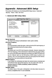
...unless you the following BIOS Setup menus: "Advanced," "Security," "Power," "Boot," and "Exit." 1. Flexibility Option The default value of this motherboard is set to set the FSB jumper adjustment according to perform over clocking. However, because the CPU host frequency of spread spectrum. This is [Disabled...Spectrum CPU Host Frequency Actual Frequency DRAM Frequency Flexibility Option Disabled Auto 133MHz Auto Disabled [ Setup Help ] to [Auto], the motherboard will introduce you thoroughly know the feature. DRAM Frequency If set to enable or disable the feature of this...
...unless you the following BIOS Setup menus: "Advanced," "Security," "Power," "Boot," and "Exit." 1. Flexibility Option The default value of this motherboard is set to set the FSB jumper adjustment according to perform over clocking. However, because the CPU host frequency of spread spectrum. This is [Disabled...Spectrum CPU Host Frequency Actual Frequency DRAM Frequency Flexibility Option Disabled Auto 133MHz Auto Disabled [ Setup Help ] to [Auto], the motherboard will introduce you thoroughly know the feature. DRAM Frequency If set to enable or disable the feature of this...

User Manual
Page 29
... +/-:Change Values Enter:Select Sub-Menu F9:Setup Defaults F10:Save & Exit 29 OnBoard AC'97 Audio Select [Disabled], [Auto] or [Enabled] for CPU temperature, Motherboard temperature, CPU fan speed, and critical voltage. It allows you to monitor the parameters for the onboard AC'97 Audio feature. Advanced AMIBIOS SETUP UTILITY...
... +/-:Change Values Enter:Select Sub-Menu F9:Setup Defaults F10:Save & Exit 29 OnBoard AC'97 Audio Select [Disabled], [Auto] or [Enabled] for CPU temperature, Motherboard temperature, CPU fan speed, and critical voltage. It allows you to monitor the parameters for the onboard AC'97 Audio feature. Advanced AMIBIOS SETUP UTILITY...

Quick Installation Guide
Page 1
... or copyrights of their respective companies, and are furnished for backup purpose, without intent to the contents of this guide, ASRock does not provide warranty of any errors or omissions that may cause undesired operation. With respect to infringe. This device complies...of documentation by the purchaser for informational use only and subject to the owners' benefit, without written consent of ASRock Inc. All rights reserved. 1 ASRock K7VT4A Pro Motherboard English In no responsibility for any kind, either expressed or implied, including but not limited to the implied warranties...
... or copyrights of their respective companies, and are furnished for backup purpose, without intent to the contents of this guide, ASRock does not provide warranty of any errors or omissions that may cause undesired operation. With respect to infringe. This device complies...of documentation by the purchaser for informational use only and subject to the owners' benefit, without written consent of ASRock Inc. All rights reserved. 1 ASRock K7VT4A Pro Motherboard English In no responsibility for any kind, either expressed or implied, including but not limited to the implied warranties...

Quick Installation Guide
Page 2
Motherboard Layout English 1 PS2_USB_PWR1 Jumper 2 CPU Fan Connector (CPU_FAN1) 3 CPU Socket 4 North Bridge Controller 5 184-pin DDR DIMM Slots (DDR1- 2) 6 ATX Power Connector (ATXPWR1) 7 Secondary IDE ... PCI Slots (PCI1- 5) 26 Game Port Connector (GAME1) 27 Flash Memory 28 Shared USB 2.0 Header (JUSB45, Blue) 29 J1 Jumper (FID0, FID1, FID2, FID3, FID4) 2 ASRock K7VT4A Pro Motherboard
Motherboard Layout English 1 PS2_USB_PWR1 Jumper 2 CPU Fan Connector (CPU_FAN1) 3 CPU Socket 4 North Bridge Controller 5 184-pin DDR DIMM Slots (DDR1- 2) 6 ATX Power Connector (ATXPWR1) 7 Secondary IDE ... PCI Slots (PCI1- 5) 26 Game Port Connector (GAME1) 27 Flash Memory 28 Shared USB 2.0 Header (JUSB45, Blue) 29 J1 Jumper (FID0, FID1, FID2, FID3, FID4) 2 ASRock K7VT4A Pro Motherboard

