
User Manual
Page 5
... to protect CPU life (ASRock U-COP)(see CAUTION 4) OS: Microsoft® Windows® 98 SE / ME / 2000 / XP compliant 5 CPU frequency stepless control (only for advanced users' reference, see CAUTION 1); North Bridge (K7VT4-8X): VIA KT400/8X (VT8377), FSB@333 MHz, AGP 8X/4X South Bridge: VIA VT8235CD, supports USB 2.0, ATA 133 Clock Generator...
... to protect CPU life (ASRock U-COP)(see CAUTION 4) OS: Microsoft® Windows® 98 SE / ME / 2000 / XP compliant 5 CPU frequency stepless control (only for advanced users' reference, see CAUTION 1); North Bridge (K7VT4-8X): VIA KT400/8X (VT8377), FSB@333 MHz, AGP 8X/4X South Bridge: VIA VT8235CD, supports USB 2.0, ATA 133 Clock Generator...
User Manual
Page 6
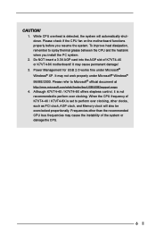
... system will also be overclocked proportionally. When the CPU frequency of K7VT4-4X / K7VT4-8X is set to perform over clocking, other than the recommended CPU bus frequencies may cause the instability of K7VT4-4X or K7VT4-8X motherboard! It may cause permanent damage! 3. Please check if... the CPU fan on the motherboard functions properly before you install the PC system. 2. To improve heat dissipation, remember to Microsoft® official document at http://www.microsoft.com/whdc/hwdev/bus/USB...
... system will also be overclocked proportionally. When the CPU frequency of K7VT4-4X / K7VT4-8X is set to perform over clocking, other than the recommended CPU bus frequencies may cause the instability of K7VT4-4X or K7VT4-8X motherboard! It may cause permanent damage! 3. Please check if... the CPU fan on the motherboard functions properly before you install the PC system. 2. To improve heat dissipation, remember to Microsoft® official document at http://www.microsoft.com/whdc/hwdev/bus/USB...

User Manual
Page 9
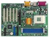
1.5 ASRock I/OTM (K7VT4-4X / K7VT4-8X) 1 2 3 10 9 8 7 654 1 Parallel port 3 Game port 5 Line In (Light Blue) 7 USB 2.0 ports 9 PS/2 keyboard port (Purple) 2 RJ-45 port 4 Microphone (Pink) 6 Line Out (Lime) 8 Serial port (COM1) 10 PS/2 mouse port (Green) 9
1.5 ASRock I/OTM (K7VT4-4X / K7VT4-8X) 1 2 3 10 9 8 7 654 1 Parallel port 3 Game port 5 Line In (Light Blue) 7 USB 2.0 ports 9 PS/2 keyboard port (Purple) 2 RJ-45 port 4 Microphone (Pink) 6 Line Out (Lime) 8 Serial port (COM1) 10 PS/2 mouse port (Green) 9

User Manual
Page 13
... side bus frequency of this motherboard is placed on these 2 pins. JR1(see p.7/p.8 item 26) JL1(see p.7/p.8 item 1) +5V +5VSB +5VSB (standby) for PS/2 or USB wake up events. 2.7 Jumpers Setup The illustration shows how jumpers are short (see fig. 1), both jumper caps on the pins, the jumper is "SHORT". When...
... side bus frequency of this motherboard is placed on these 2 pins. JR1(see p.7/p.8 item 26) JL1(see p.7/p.8 item 1) +5V +5VSB +5VSB (standby) for PS/2 or USB wake up events. 2.7 Jumpers Setup The illustration shows how jumpers are short (see fig. 1), both jumper caps on the pins, the jumper is "SHORT". When...

User Manual
Page 16
... Red marking Note: Match the red marking on the rear panel are NOT jumpers. These connectors allow you to the secondary IDE connector (IDE2, black). USB 2.0 header (9-pin USB45) (see p.7/p.8 item 28) IRTX +5V DUMMY 1 GND IRRX AUX-L GND GND AUX-R CD-L GND GND CD-R AUX1 ...see p.7/p.8 item 17) Internal audio connectors (4-pin CD1, 4-pin AUX1) (CD1: see p.7/p.8 item 27) (AUX1: see p.7/p.8 item 16) USB_PWR P-5 P+5 GND DUMMY 1 GND P+4 P-4 USB_PWR ASRock I/OTM provides you four default USB 2.0 ports on the rear panel. 2.8 Connectors Connectors are not sufficient, you may use this...
... Red marking Note: Match the red marking on the rear panel are NOT jumpers. These connectors allow you to the secondary IDE connector (IDE2, black). USB 2.0 header (9-pin USB45) (see p.7/p.8 item 28) IRTX +5V DUMMY 1 GND IRRX AUX-L GND GND AUX-R CD-L GND GND CD-R AUX1 ...see p.7/p.8 item 17) Internal audio connectors (4-pin CD1, 4-pin AUX1) (CD1: see p.7/p.8 item 27) (AUX1: see p.7/p.8 item 16) USB_PWR P-5 P+5 GND DUMMY 1 GND P+4 P-4 USB_PWR ASRock I/OTM provides you four default USB 2.0 ports on the rear panel. 2.8 Connectors Connectors are not sufficient, you may use this...

User Manual
Page 24
... PCI Delay Transaction feature will be set to enable or disable the feature of USB controller. Disable this to enable or disable the support to enable "Over Vcore Voltage" feature. Doing so may select [4X], [2X], or [1X] as mouse, keyboard,... etc. Chipset Configuration: Advanced...USB Controller: Use this feature will free the PCI Bus when the CPU is [Disabled]. Please note that are not PCI 2.1 compliant. F1:Help Esc:Previous Menu :Select Item +/-:Change Values Enter:Select Sub-Menu F9:Setup Defaults F10:Save & Exit AGP Mode: If K7VT4-4X motherboard is installed on K7VT4...
... PCI Delay Transaction feature will be set to enable or disable the feature of USB controller. Disable this to enable or disable the support to enable "Over Vcore Voltage" feature. Doing so may select [4X], [2X], or [1X] as mouse, keyboard,... etc. Chipset Configuration: Advanced...USB Controller: Use this feature will free the PCI Bus when the CPU is [Disabled]. Please note that are not PCI 2.1 compliant. F1:Help Esc:Previous Menu :Select Item +/-:Change Values Enter:Select Sub-Menu F9:Setup Defaults F10:Save & Exit AGP Mode: If K7VT4-4X motherboard is installed on K7VT4...


