User Manual
Page 3
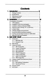
...) Hard Disks Installation 21 2.8 Hot Plug and Hot Swap Functions for SATA HDDs .......... 21 2.9 Making An SATA Driver Diskette 22 3 . Introduction 5 1.1 Package Contents 5 1.2 Specifications 6 1.3 Motherboard Layout 8 1.4 ASRock I/O Plus 9 TM ...2 . BIOS SETUP UTILITY 23 3.1 Introduction 23 3.1.1 BIOS Menu Bar 23 3.1.2 Navigation Keys 24 3.2 Main Screen 24 3.3 Advanced Screen 25 3.3.1 CPU Configuration 26 3.3.2 Chipset...
...) Hard Disks Installation 21 2.8 Hot Plug and Hot Swap Functions for SATA HDDs .......... 21 2.9 Making An SATA Driver Diskette 22 3 . Introduction 5 1.1 Package Contents 5 1.2 Specifications 6 1.3 Motherboard Layout 8 1.4 ASRock I/O Plus 9 TM ...2 . BIOS SETUP UTILITY 23 3.1 Introduction 23 3.1.1 BIOS Menu Bar 23 3.1.2 Navigation Keys 24 3.2 Main Screen 24 3.3 Advanced Screen 25 3.3.1 CPU Configuration 26 3.3.2 Chipset...

User Manual
Page 5
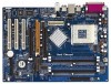
... to change without further notice. ASRock website http://www.asrock.com 1.1 Package Contents ASRock K7Upgrade-880 Motherboard (ATX Form Factor: 12.0-in x 8.5-in, 30.5 cm x 21.6 cm) ASRock K7Upgrade-880 Quick Installation Guide ASRock K7Upgrade-880 Support CD One 80-conductor Ultra ATA 66/100/133 IDE Ribbon Cable One Ribbon Cable for purchasing ASRock K7Upgrade-880 motherboard, a reliable motherboard produced under ASRock's consistently stringent quality control. 1. You...
... to change without further notice. ASRock website http://www.asrock.com 1.1 Package Contents ASRock K7Upgrade-880 Motherboard (ATX Form Factor: 12.0-in x 8.5-in, 30.5 cm x 21.6 cm) ASRock K7Upgrade-880 Quick Installation Guide ASRock K7Upgrade-880 Support CD One 80-conductor Ultra ATA 66/100/133 IDE Ribbon Cable One Ribbon Cable for purchasing ASRock K7Upgrade-880 motherboard, a reliable motherboard produced under ASRock's consistently stringent quality control. 1. You...

User Manual
Page 6
... Audio: 5.1 channels AC'97 Audio LAN: Speed: 802.3u (10/100 Ethernet), supports Wake-On-LAN Hardware Monitor: CPU Temperature Sensing Motherboard Temperature Sensing CPU Overheat Shutdown to Protect CPU Life (ASRock U-COP)(see CAUTION 2) CPU Fan Tachometer Chassis Fan Tachometer Voltage Monitoring: +12V, +5V, +3.3V, Vcore K8 Bridge: Supports CPU upgrade...
... Audio: 5.1 channels AC'97 Audio LAN: Speed: 802.3u (10/100 Ethernet), supports Wake-On-LAN Hardware Monitor: CPU Temperature Sensing Motherboard Temperature Sensing CPU Overheat Shutdown to Protect CPU Life (ASRock U-COP)(see CAUTION 2) CPU Fan Tachometer Chassis Fan Tachometer Voltage Monitoring: +12V, +5V, +3.3V, Vcore K8 Bridge: Supports CPU upgrade...

User Manual
Page 7
...as the FSB setting in BIOS setup. To improve heat dissipation, remember to read the installation guide of this motherboard! Power Management for proper installation. 2. Although this motherboard offers stepless control, it back again. While CPU overheat is determined by the jumper-setting. The CPU host... the AGP slot of the system or damage the CPU. ASRock I/O PlusTM: 1 PS/2 mouse port, 1 PS/2 keyboard port, 1 serial port: COM1, 1 parallel port: ECP/EPP support, 6 ready-to-use a 3.3V AGP card on the motherboard functions properly and unplug the power cord, then plug it...
...as the FSB setting in BIOS setup. To improve heat dissipation, remember to read the installation guide of this motherboard! Power Management for proper installation. 2. Although this motherboard offers stepless control, it back again. While CPU overheat is determined by the jumper-setting. The CPU host... the AGP slot of the system or damage the CPU. ASRock I/O PlusTM: 1 PS/2 mouse port, 1 PS/2 keyboard port, 1 serial port: COM1, 1 parallel port: ECP/EPP support, 6 ready-to-use a 3.3V AGP card on the motherboard functions properly and unplug the power cord, then plug it...

User Manual
Page 8
... (IDE2, Black) 9 Primary IDE Connector (IDE1, Blue) 10 FSB Select Jumpers (FSB_SEL0, FSB_SEL1) 11 2 x 184-pin DDR DIMM Slots (Dual Channel B: DDR2, DDR4; PARALLEL PORT 1.3 Motherboard Layout PS2 Mouse PS2 Keyboard 1 2 34 5 21.6cm (8.5 in) 1 PS2_USB_PWR1 CPU_FAN1 1 J1 67 ATX12V1 SOCKET 462 COM1 IDE2 8 ATXPWR1 DDR1 (64/72 bit, 184-pin...
... (IDE2, Black) 9 Primary IDE Connector (IDE1, Blue) 10 FSB Select Jumpers (FSB_SEL0, FSB_SEL1) 11 2 x 184-pin DDR DIMM Slots (Dual Channel B: DDR2, DDR4; PARALLEL PORT 1.3 Motherboard Layout PS2 Mouse PS2 Keyboard 1 2 34 5 21.6cm (8.5 in) 1 PS2_USB_PWR1 CPU_FAN1 1 J1 67 ATX12V1 SOCKET 462 COM1 IDE2 8 ATXPWR1 DDR1 (64/72 bit, 184-pin...
User Manual
Page 10
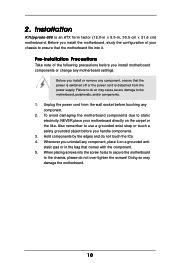
... placing screws into it on the carpet or the like. Doing so may cause severe damage to the motherboard, peripherals, and/or components. 1. Also remember to do so may damage the motherboard. 10 Installation K7Upgrade-880 is detached from the wall socket before you handle components. 3. Failure to use a grounded wrist strap or touch...
... placing screws into it on the carpet or the like. Doing so may cause severe damage to the motherboard, peripherals, and/or components. 1. Also remember to do so may damage the motherboard. 10 Installation K7Upgrade-880 is detached from the wall socket before you handle components. 3. Failure to use a grounded wrist strap or touch...

User Manual
Page 11
... necessary to install a larger heatsink and cooling fan to secure the CPU. The lever clicks on the socket while you install the CPU into this motherboard, it fits in good contact with each other. You also need to spray thermal grease between the CPU and the heatsink to a 90° angle...
... necessary to install a larger heatsink and cooling fan to secure the CPU. The lever clicks on the socket while you install the CPU into this motherboard, it fits in good contact with each other. You also need to spray thermal grease between the CPU and the heatsink to a 90° angle...
User Manual
Page 12
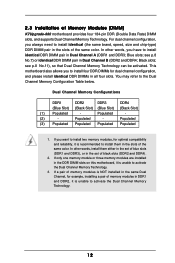
...slots of memory modules in DDR1 and DDR2, it is unable to install them either in the set of Memory Modules (DIMM) K7Upgrade-880 motherboard provides four 184-pin DDR (Double Data Rate) DIMM slots, and supports Dual Channel Memory Technology. For dual channel configuration, ...you have to activate the Dual Channel Memory Technology. 3. Populated - This motherboard also allows you want to install two memory modules, for example, installing a pair of the same color. If a pair of memory modules...
...slots of memory modules in DDR1 and DDR2, it is unable to install them either in the set of Memory Modules (DIMM) K7Upgrade-880 motherboard provides four 184-pin DDR (Double Data Rate) DIMM slots, and supports Dual Channel Memory Technology. For dual channel configuration, ...you have to activate the Dual Channel Memory Technology. 3. Populated - This motherboard also allows you want to install two memory modules, for example, installing a pair of the same color. If a pair of memory modules...

User Manual
Page 13
... 3. Step 1. Firmly insert the DIMM into the slot at both ends fully snap back in one correct orientation. Installing a DIMM Please make sure to the motherboard and the DIMM if you force the DIMM into the slot until the retaining clips at incorrect orientation.
... 3. Step 1. Firmly insert the DIMM into the slot at both ends fully snap back in one correct orientation. Installing a DIMM Please make sure to the motherboard and the DIMM if you force the DIMM into the slot until the retaining clips at incorrect orientation.

User Manual
Page 14
... the slot AGP2 supports for the correct jumper settings. short pin1, pin2) 754-Pin CPU J2 / J3 / J14 (page 8, No. 12) (Using an add-on K7Upgrade-880 motherboard. short ) (5 x 2-pin; open ) J7 / J8 (page 8, No. 16) 3 2 J9 / J10 J11 / J13 (page 8, No. 14) 2_3 (5 x 3-pin; open ) J4 ...) is not an AGP slot, and the brown-colored Bridge (K8BRIDGE_2) is necessary to adjust the jumper settings for those required jumpers on ASRock 754Bridge (optional) into the brown-colored Bridge (K8BRIDGE_2)! CPU Type 462-Pin CPU (Default) Jumper Settings 2-Pin Jumpers J2 / J3 /...
... the slot AGP2 supports for the correct jumper settings. short pin1, pin2) 754-Pin CPU J2 / J3 / J14 (page 8, No. 12) (Using an add-on K7Upgrade-880 motherboard. short ) (5 x 2-pin; open ) J7 / J8 (page 8, No. 16) 3 2 J9 / J10 J11 / J13 (page 8, No. 14) 2_3 (5 x 3-pin; open ) J4 ...) is not an AGP slot, and the brown-colored Bridge (K8BRIDGE_2) is necessary to adjust the jumper settings for those required jumpers on ASRock 754Bridge (optional) into the brown-colored Bridge (K8BRIDGE_2)! CPU Type 462-Pin CPU (Default) Jumper Settings 2-Pin Jumpers J2 / J3 /...

User Manual
Page 15
... slots are used to the hardware. It may cause permanent damage to install a graphics card. Remove the system unit cover (if your motherboard package, and please follow the "Jumper Cap Remover Instruction" to the chassis with K8 AGP Interface into the slot AGP2 (see page 8 No...documentation of the expansion card and make sure that the power supply is switched off or the power cord is already installed in your motherboard is unplugged. Step 4. Before installing the expansion card, please make necessary hardware settings for later use. Step 3. Replace the system cover...
... slots are used to the hardware. It may cause permanent damage to install a graphics card. Remove the system unit cover (if your motherboard package, and please follow the "Jumper Cap Remover Instruction" to the chassis with K8 AGP Interface into the slot AGP2 (see page 8 No...documentation of the expansion card and make sure that the power supply is switched off or the power cord is already installed in your motherboard is unplugged. Step 4. Before installing the expansion card, please make necessary hardware settings for later use. Step 3. Replace the system cover...
User Manual
Page 16
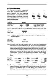
.../2 or USB wake up the system first, and then shut it requires 2 Amp and higher standby current provided by means of the adjustment of this motherboard is "Open". However, please do the clear-CMOS action. If you must set the CPU front side bus frequency. 16 When the jumper cap is...
.../2 or USB wake up the system first, and then shut it requires 2 Amp and higher standby current provided by means of the adjustment of this motherboard is "Open". However, please do the clear-CMOS action. If you must set the CPU front side bus frequency. 16 When the jumper cap is...

User Manual
Page 18
... 9) (39-pin IDE2, see p.8, No. 8) PIN1 IDE1 PIN1 IDE2 connect the blue end connect the black end to the motherboard to the instruction of the motherboard! 2.6 Onboard Headers and Connectors Onboard headers and connectors are NOT jumpers. Do NOT place jumper caps over the headers and connectors will ... disk drive to the primary IDE connector (IDE1, blue) and CD-ROM to the SATA hard disk or the SATA connector on this motherboard, please set the IDE device as "Master". Besides, to optimize compatibility and performance, please connect your IDE device vendor for internal storage ...
... 9) (39-pin IDE2, see p.8, No. 8) PIN1 IDE1 PIN1 IDE2 connect the blue end connect the black end to the motherboard to the instruction of the motherboard! 2.6 Onboard Headers and Connectors Onboard headers and connectors are NOT jumpers. Do NOT place jumper caps over the headers and connectors will ... disk drive to the primary IDE connector (IDE1, blue) and CD-ROM to the SATA hard disk or the SATA connector on this motherboard, please set the IDE device as "Master". Besides, to optimize compatibility and performance, please connect your IDE device vendor for internal storage ...
User Manual
Page 21
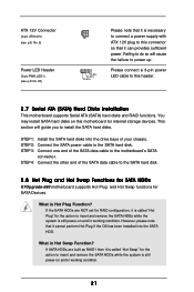
...STEP 4: Connect the other end of the SATA data cable to the SATA hard disk. 2.8 Hot Plug and Hot Swap Functions for SATA HDDs K7Upgrade-880 motherboard supports Hot Plug and Hot Swap functions for internal storage devices. What is Hot Swap Function? What is Hot Plug Function? STEP 3: Connect one ... you to install the SATA hard disks. STEP 2: Connect the SATA power cable to this header. 2.7 Serial ATA (SATA) Hard Disks Installation This motherboard supports Serial ATA (SATA) hard disks and RAID functions. If the SATA HDDs are built as RAID1 then it is called "Hot Swap" for the...
...STEP 4: Connect the other end of the SATA data cable to the SATA hard disk. 2.8 Hot Plug and Hot Swap Functions for SATA HDDs K7Upgrade-880 motherboard supports Hot Plug and Hot Swap functions for internal storage devices. What is Hot Swap Function? What is Hot Plug Function? STEP 3: Connect one ... you to install the SATA hard disks. STEP 2: Connect the SATA power cable to this header. 2.7 Serial ATA (SATA) Hard Disks Installation This motherboard supports Serial ATA (SATA) hard disks and RAID functions. If the SATA HDDs are built as RAID1 then it is called "Hot Swap" for the...

User Manual
Page 23
... press to enter the BIOS SETUP UTILITY after POST, restart the system by pressing + + , or by turning the system off and then back on the motherboard stores the BIOS SETUP UTILITY.
... press to enter the BIOS SETUP UTILITY after POST, restart the system by pressing + + , or by turning the system off and then back on the motherboard stores the BIOS SETUP UTILITY.
User Manual
Page 25
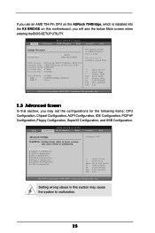
... Configuration. BIOS SETUP UTILITY Main Advanced H/W Monitor Boot Security Exit System Overview System Time System Date [17:00:09] [Mon 08/02/2004] BIOS Version : K7Upgrade-880 W/754Bridge BIOS P1.0 Processor Type : AMD Athlon(tm) 64 Processor 3400+ Processor Speed : 2200 MHz L1 Cache Size : 128KB L2 Cache Size : 1024KB Total Memory... Screen In this section, you will see the below sections may cause system to malfunction. If you use an AMD 754-Pin CPU on the ASRock 754Bridge, which is installed into the K8 BRIDGE on this motherboard, you may cause the system to malfunction. 25
... Configuration. BIOS SETUP UTILITY Main Advanced H/W Monitor Boot Security Exit System Overview System Time System Date [17:00:09] [Mon 08/02/2004] BIOS Version : K7Upgrade-880 W/754Bridge BIOS P1.0 Processor Type : AMD Athlon(tm) 64 Processor 3400+ Processor Speed : 2200 MHz L1 Cache Size : 128KB L2 Cache Size : 1024KB Total Memory... Screen In this section, you will see the below sections may cause system to malfunction. If you use an AMD 754-Pin CPU on the ASRock 754Bridge, which is installed into the K8 BRIDGE on this motherboard, you may cause the system to malfunction. 25
User Manual
Page 26
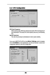
... v02.54 (C) Copyright 1985-2003, American Megatrends, Inc. 26 CPU Host Frequency While entering setup, BIOS auto detects the present CPU host frequency of this motherboard, you use an AMD 754-Pin CPU on the ASRock 754Bridge, which is installed into the K8 BRIDGE on this...
... v02.54 (C) Copyright 1985-2003, American Megatrends, Inc. 26 CPU Host Frequency While entering setup, BIOS auto detects the present CPU host frequency of this motherboard, you use an AMD 754-Pin CPU on the ASRock 754Bridge, which is installed into the K8 BRIDGE on this...

User Manual
Page 27
... of "Processor Maximum Multiplier". otherwise, it is not recommended to adjust the value of this item. You may set to adjust the value of this motherboard. Spread Spectrum This item should always be hidden. Cool 'n' Quiet Use this item to [Auto] by default. If it is recommended to [Manual], you set...
... of "Processor Maximum Multiplier". otherwise, it is not recommended to adjust the value of this item. You may set to adjust the value of this motherboard. Spread Spectrum This item should always be hidden. Cool 'n' Quiet Use this item to [Auto] by default. If it is recommended to [Manual], you set...

User Manual
Page 29
... Bus Selection The default value is [Auto], which will allow better tolerance for the system. The default vaule is [2T Command]. It is selected, the motherboard will detect the memory module(s) inserted and assigns appropriate frequency automatically. DRAM Frequency If [Auto] is recommended to [Enabled]. 3.3.2 Chipset Configuration BIOS SETUP UTILITY Advanced...
... Bus Selection The default value is [Auto], which will allow better tolerance for the system. The default vaule is [2T Command]. It is selected, the motherboard will detect the memory module(s) inserted and assigns appropriate frequency automatically. DRAM Frequency If [Auto] is recommended to [Enabled]. 3.3.2 Chipset Configuration BIOS SETUP UTILITY Advanced...

User Manual
Page 30
If you install an 8X-AGP card on this motherboard, you will free the PCI Bus when the CPU is [Auto]. 30 BIOS SETUP UTILITY Advanced Chipset Settings VCCM Primary Graphics Adapter AGP Aperture Size ... [Auto], [8X] or [4X] as [Auto], [4X], [2X], or [1X]. If you use an AMD 754-Pin CPU on the ASRock 754Bridge, which is installed into the K8 BRIDGE on this motherboard, you may set the AGP mode as the AGP mode. OnBoard AC'97 Audio Select [Enabled] or [Disabled] for the...
If you install an 8X-AGP card on this motherboard, you will free the PCI Bus when the CPU is [Auto]. 30 BIOS SETUP UTILITY Advanced Chipset Settings VCCM Primary Graphics Adapter AGP Aperture Size ... [Auto], [8X] or [4X] as [Auto], [4X], [2X], or [1X]. If you use an AMD 754-Pin CPU on the ASRock 754Bridge, which is installed into the K8 BRIDGE on this motherboard, you may set the AGP mode as the AGP mode. OnBoard AC'97 Audio Select [Enabled] or [Disabled] for the...

