User Manual
Page 3
Introduction 5 1.1 Package Contents 5 1.2 Specifications 6 1.3 Motherboard Layout 8 1.4 ASRock I/O Plus 9 TM ...2 . BIOS SETUP UTILITY 23 3.1 Introduction 23 3.1.1 BIOS Menu Bar 23 3.1.2 Navigation Keys 24 3.2 Main Screen 24 3.3 Advanced Screen 25 3.3.1 CPU Configuration 26 3.3.2 Chipset ... 2.3 Installation of Memory Modules (DIMM 12 2.4 Expansion Slots (K8 Bridge, PCI, and AGP Slots 14 2.5 Jumpers Setup 16 2.6 Onboard Headers and Connectors 18 2.7 Serial ATA (SATA) Hard Disks Installation 21 2.8 Hot Plug and Hot Swap Functions for...
Introduction 5 1.1 Package Contents 5 1.2 Specifications 6 1.3 Motherboard Layout 8 1.4 ASRock I/O Plus 9 TM ...2 . BIOS SETUP UTILITY 23 3.1 Introduction 23 3.1.1 BIOS Menu Bar 23 3.1.2 Navigation Keys 24 3.2 Main Screen 24 3.3 Advanced Screen 25 3.3.1 CPU Configuration 26 3.3.2 Chipset ... 2.3 Installation of Memory Modules (DIMM 12 2.4 Expansion Slots (K8 Bridge, PCI, and AGP Slots 14 2.5 Jumpers Setup 16 2.6 Onboard Headers and Connectors 18 2.7 Serial ATA (SATA) Hard Disks Installation 21 2.8 Hot Plug and Hot Swap Functions for...

User Manual
Page 5
Introduction Thank you for a 3.5-in Floppy Drive One Serial ATA (SATA) Data Cable One Serial ATA (SATA) HDD Power Cable(Optional) One ASRock I/O PlusTM Shield One Jumper Cap Remover 5 Because the motherboard specifications and the BIOS software might be updated... the motherboard and step-bystep guide to quality and endurance. ASRock website http://www.asrock.com 1.1 Package Contents ASRock K7Upgrade-880 Motherboard (ATX Form Factor: 12.0-in x 8.5-in, 30.5 cm x 21.6 cm) ASRock K7Upgrade-880 Quick Installation Guide ASRock K7Upgrade-880 Support CD One 80-conductor Ultra ATA 66/100/133 IDE...
Introduction Thank you for a 3.5-in Floppy Drive One Serial ATA (SATA) Data Cable One Serial ATA (SATA) HDD Power Cable(Optional) One ASRock I/O PlusTM Shield One Jumper Cap Remover 5 Because the motherboard specifications and the BIOS software might be updated... the motherboard and step-bystep guide to quality and endurance. ASRock website http://www.asrock.com 1.1 Package Contents ASRock K7Upgrade-880 Motherboard (ATX Form Factor: 12.0-in x 8.5-in, 30.5 cm x 21.6 cm) ASRock K7Upgrade-880 Quick Installation Guide ASRock K7Upgrade-880 Support CD One 80-conductor Ultra ATA 66/100/133 IDE...

User Manual
Page 6
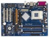
... XP / DuronTM and 32-bit Sempron Processor Chipsets: North Bridge: VIA KT880, FSB @ 400 MHz South Bridge: VIA VT8237, supports USB 2.0, ATA 133, SATA 1.5Gb/s Memory: 4 DDR DIMM Slots: DDR1, DDR2, DDR3, and DDR4 Support PC3200 (DDR400) / PC2700 (DDR333) / PC2100 (DDR266), Max. 4GB ...3u (10/100 Ethernet), supports Wake-On-LAN Hardware Monitor: CPU Temperature Sensing Motherboard Temperature Sensing CPU Overheat Shutdown to Protect CPU Life (ASRock U-COP)(see CAUTION 2) CPU Fan Tachometer Chassis Fan Tachometer Voltage Monitoring: +12V, +5V, +3.3V, Vcore K8 Bridge: Supports CPU ...
... XP / DuronTM and 32-bit Sempron Processor Chipsets: North Bridge: VIA KT880, FSB @ 400 MHz South Bridge: VIA VT8237, supports USB 2.0, ATA 133, SATA 1.5Gb/s Memory: 4 DDR DIMM Slots: DDR1, DDR2, DDR3, and DDR4 Support PC3200 (DDR400) / PC2700 (DDR333) / PC2100 (DDR266), Max. 4GB ...3u (10/100 Ethernet), supports Wake-On-LAN Hardware Monitor: CPU Temperature Sensing Motherboard Temperature Sensing CPU Overheat Shutdown to Protect CPU Life (ASRock U-COP)(see CAUTION 2) CPU Fan Tachometer Chassis Fan Tachometer Voltage Monitoring: +12V, +5V, +3.3V, Vcore K8 Bridge: Supports CPU ...

User Manual
Page 18
...(see p.8, No. 8) PIN1 IDE1 PIN1 IDE2 connect the blue end connect the black end to the motherboard to the SATA hard disk or the SATA connector on this motherboard, please set the IDE device as "Master". Besides, to optimize compatibility and performance, please connect ...your IDE device vendor for internal storage devices. The current SATA interface allows up to the secondary IDE connector (IDE2, black). 2.6 Onboard Headers and Connectors Onboard headers and connectors are NOT jumpers....
...(see p.8, No. 8) PIN1 IDE1 PIN1 IDE2 connect the blue end connect the black end to the motherboard to the SATA hard disk or the SATA connector on this motherboard, please set the IDE device as "Master". Besides, to optimize compatibility and performance, please connect ...your IDE device vendor for internal storage devices. The current SATA interface allows up to the secondary IDE connector (IDE2, black). 2.6 Onboard Headers and Connectors Onboard headers and connectors are NOT jumpers....

User Manual
Page 19
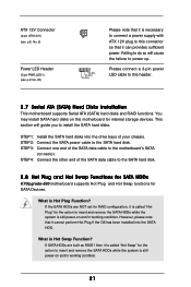
... optional wireless transmitting and receiving infrared module. USB 2.0 Header (9-pin USB67) (see p.8, No. 25) USB_PWR P-7 P+7 GND DUMMY 1 GND P+6 P-6 USB_PWR ASRock I/O PlusTM provides you to function. Shared USB 2.0 Header (9-pin USB45) (see p.8, No. 39) CD-R GND GND CD-L AUX-R GND GND AUX-L ...USB45 connector is shared with the USB 2.0 ports 4,5 on ASRock I /O PlusTM. Serial ATA (SATA) Power Cable (Optional) connect to the SATA HDD power connector connect to the power supply Please connect the black end of SATA power cable to the power connector of the power supply. ...
... optional wireless transmitting and receiving infrared module. USB 2.0 Header (9-pin USB67) (see p.8, No. 25) USB_PWR P-7 P+7 GND DUMMY 1 GND P+6 P-6 USB_PWR ASRock I/O PlusTM provides you to function. Shared USB 2.0 Header (9-pin USB45) (see p.8, No. 39) CD-R GND GND CD-L AUX-R GND GND AUX-L ...USB45 connector is shared with the USB 2.0 ports 4,5 on ASRock I /O PlusTM. Serial ATA (SATA) Power Cable (Optional) connect to the SATA HDD power connector connect to the power supply Please connect the black end of SATA power cable to the power connector of the power supply. ...
User Manual
Page 21
... OS has been installed into the drive bays of the SATA data cable to power up. This section will cause the failure to the SATA hard disk. 2.8 Hot Plug and Hot Swap Functions for SATA HDDs K7Upgrade-880 motherboard supports Hot Plug and Hot Swap functions for internal ...storage devices. STEP 2: Connect the SATA power cable to the motherboard's SATA connector. What is Hot Plug Function? STEP 1: Install the SATA hard disks into the SATA HDD. What is Hot Swap ...
... OS has been installed into the drive bays of the SATA data cable to power up. This section will cause the failure to the SATA hard disk. 2.8 Hot Plug and Hot Swap Functions for SATA HDDs K7Upgrade-880 motherboard supports Hot Plug and Hot Swap functions for internal ...storage devices. STEP 2: Connect the SATA power cable to the motherboard's SATA connector. What is Hot Plug Function? STEP 1: Install the SATA hard disks into the SATA HDD. What is Hot Swap ...

User Manual
Page 22
...start to use "VT8237 SATA RAID BIOS" to boot your system. (Do NOT insert any floppy diskette into the floppy drive at this moment!) STEP 2: During POST at the beginning of system boot-up, press key, and then a window for proper configuration. STEP 1: Insert the ASRock Support CD into the floppy...Serial ATA driver diskette [YN]?", press . STEP 5: The system will lose ALL data in Windows environment. 2.9 Making An SATA Driver Diskette If you want to install Windows 2000 or Windows XP on your SATA HDDs, you will see the message on your system, or you may also set RAID 0 / RAID 1 / JBOD...
...start to use "VT8237 SATA RAID BIOS" to boot your system. (Do NOT insert any floppy diskette into the floppy drive at this moment!) STEP 2: During POST at the beginning of system boot-up, press key, and then a window for proper configuration. STEP 1: Insert the ASRock Support CD into the floppy...Serial ATA driver diskette [YN]?", press . STEP 5: The system will lose ALL data in Windows environment. 2.9 Making An SATA Driver Diskette If you want to install Windows 2000 or Windows XP on your SATA HDDs, you will see the message on your system, or you may also set RAID 0 / RAID 1 / JBOD...
