

RAID Installation Guide
Page 9
Select "Select Disk Drives" to select the disk drives and create array automatically. Select "Auto Setup" to allow BIOS to let user select the array drives manually. When using Select Disk Drives method, the channel column will be activated. Just highlight the target drives that you want to use and press to create a disk array. One method is "Auto Setup", and another is "Select Disk Drives". There are two methods to select them respectively. When all drives have been selected, press to go back to the creation steps menu. 9 3.
Select "Select Disk Drives" to select the disk drives and create array automatically. Select "Auto Setup" to allow BIOS to let user select the array drives manually. When using Select Disk Drives method, the channel column will be activated. Just highlight the target drives that you want to use and press to create a disk array. One method is "Auto Setup", and another is "Select Disk Drives". There are two methods to select them respectively. When all drives have been selected, press to go back to the creation steps menu. 9 3.

User Manual
Page 1
All rights reserved. 1 MOTHERBOARD K7Upgrade-600 User Manual Version 1.1 Published August 2004 Copyright©2004 ASRock INC.
All rights reserved. 1 MOTHERBOARD K7Upgrade-600 User Manual Version 1.1 Published August 2004 Copyright©2004 ASRock INC.

User Manual
Page 2
With respect to the contents of this manual, ASRock does not provide warranty of any defect or error in the manual or product. In no responsibility for any errors or omissions that may not be registered trademarks or copyrights of their respective companies, and are... data, interruption of business and the like), even if ASRock has been advised of the possibility of such damages arising from any kind, either expressed or implied, including but not limited to infringe. Products and corporate names appearing in this manual may or may cause undesired operation. Copyright Notice: No...
With respect to the contents of this manual, ASRock does not provide warranty of any defect or error in the manual or product. In no responsibility for any errors or omissions that may not be registered trademarks or copyrights of their respective companies, and are... data, interruption of business and the like), even if ASRock has been advised of the possibility of such damages arising from any kind, either expressed or implied, including but not limited to infringe. Products and corporate names appearing in this manual may or may cause undesired operation. Copyright Notice: No...

User Manual
Page 5
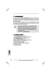
... manual, chapter 1 and 2 contain introduction of the Support CD. Introduction Thank you for a 3.5-in , 30.5 cm x 20.8 cm) ASRock K7Upgrade-600 Quick Installation Guide ASRock K7Upgrade-600 Support CD One 80-conductor Ultra ATA 66/100/133 IDE Ribbon Cable One Ribbon Cable for purchasing ASRock K7Upgrade-600 motherboard, a reliable motherboard produced under ASRock's consistently stringent quality control. ASRock website http://www.asrock...
... manual, chapter 1 and 2 contain introduction of the Support CD. Introduction Thank you for a 3.5-in , 30.5 cm x 20.8 cm) ASRock K7Upgrade-600 Quick Installation Guide ASRock K7Upgrade-600 Support CD One 80-conductor Ultra ATA 66/100/133 IDE Ribbon Cable One Ribbon Cable for purchasing ASRock K7Upgrade-600 motherboard, a reliable motherboard produced under ASRock's consistently stringent quality control. ASRock website http://www.asrock...
User Manual
Page 7
... of this motherboard is determined by the jumper-setting. Frequencies other than the recommended CPU bus frequencies may cause permanent damage! 3. Do NOT use the "Manual" option as the FSB setting in BIOS setup. Please refer to spray thermal grease between the CPU and the heatsink when you install the PC...
... of this motherboard is determined by the jumper-setting. Frequencies other than the recommended CPU bus frequencies may cause permanent damage! 3. Do NOT use the "Manual" option as the FSB setting in BIOS setup. Please refer to spray thermal grease between the CPU and the heatsink when you install the PC...

User Manual
Page 11
... to secure the CPU. Carefully insert the CPU into the socket to a 90° angle. Step 4. For proper installation, please kindly refer to the instruction manuals of CPU Fan and Heatsink After you push down the socket lever to the CPU FAN connector (CPU_FAN1, see Page 8, No. 2). Step 2. Unlock the socket...
... to secure the CPU. Carefully insert the CPU into the socket to a 90° angle. Step 4. For proper installation, please kindly refer to the instruction manuals of CPU Fan and Heatsink After you push down the socket lever to the CPU FAN connector (CPU_FAN1, see Page 8, No. 2). Step 2. Unlock the socket...

User Manual
Page 15
... to clear the data in CMOS includes system setup information such as the FSB setting in BIOS setup. After waiting for 15 seconds, use the "Manual" option as system password, date, time, and system setup parameters. When the jumper cap is placed on pins, the jumper is placed on these 2 pins...
... to clear the data in CMOS includes system setup information such as the FSB setting in BIOS setup. After waiting for 15 seconds, use the "Manual" option as system password, date, time, and system setup parameters. When the jumper cap is placed on pins, the jumper is placed on these 2 pins...

User Manual
Page 24
...Esc:Previous Menu :Select Item +/-:Change Values Enter:Select Sub-Menu F9:Setup Defaults F10:Save & Exit [USER]: It allows user to manually enter the number of cylinders, heads, and sectors per track for the remaining fields on this sub-menu. Incorrect settings may detect incorrect...Primary IDE Master", "Primary IDE Slave", "Secondary IDE Master", and "Secondary IDE Slave" to make configuration of drive, Or Select [AUTO] to manually enter the IDE hard disk drive parameters. After entering the hard disk information into or read the data from the installed hard disk. In these...
...Esc:Previous Menu :Select Item +/-:Change Values Enter:Select Sub-Menu F9:Setup Defaults F10:Save & Exit [USER]: It allows user to manually enter the number of cylinders, heads, and sectors per track for the remaining fields on this sub-menu. Incorrect settings may detect incorrect...Primary IDE Master", "Primary IDE Slave", "Secondary IDE Master", and "Secondary IDE Slave" to make configuration of drive, Or Select [AUTO] to manually enter the IDE hard disk drive parameters. After entering the hard disk information into or read the data from the installed hard disk. In these...

User Manual
Page 26
...detect the inserted memory module(s) and automatically assign appropriate frequency. CPU Host Frequency [Auto] It is determined by the jumper-setting. [Manual] This allows user to set to perform over clocking. This is not recommended unless you use this option is set CPU host frequency... manually. It will introduce you the following BIOS Setup menus: "Advanced," "Security," "Power," "Boot," and "Exit." 3.3.1. 3.3 Advanced, Security, Power, Boot, ...
...detect the inserted memory module(s) and automatically assign appropriate frequency. CPU Host Frequency [Auto] It is determined by the jumper-setting. [Manual] This allows user to set to perform over clocking. This is not recommended unless you use this option is set CPU host frequency... manually. It will introduce you the following BIOS Setup menus: "Advanced," "Security," "Power," "Boot," and "Exit." 3.3.1. 3.3 Advanced, Security, Power, Boot, ...

User Manual
Page 38
... memory accessing. The default value is not recommended to adjust the value of this option is set to 8 or 4 beats. You can be set to [Manual]; However, for safety and system stability, it is [Disabled]. TRCD Use this item to adjust the Minimum RAS# Active time of memory accessing. Flexibility Option...
... memory accessing. The default value is not recommended to adjust the value of this option is set to 8 or 4 beats. You can be set to [Manual]; However, for safety and system stability, it is [Disabled]. TRCD Use this item to adjust the Minimum RAS# Active time of memory accessing. Flexibility Option...
Quick Installation Guide
Page 4
... 1.1 Package Contents ASRock K7Upgrade-600 Motherboard (ATX Form Factor: 12.0-in x 8.2-in, 30.5 cm x 20.8 cm) ASRock K7Upgrade-600 Quick Installation Guide ASRock K7Upgrade-600 Support CD One 80-conductor Ultra ATA 66/100/133 IDE Ribbon Cable One Ribbon Cable for purchasing ASRock K7Upgrade-600 motherboard, a reliable motherboard produced under ASRock's consistently stringent quality control. More detailed information of this manual will be...
... 1.1 Package Contents ASRock K7Upgrade-600 Motherboard (ATX Form Factor: 12.0-in x 8.2-in, 30.5 cm x 20.8 cm) ASRock K7Upgrade-600 Quick Installation Guide ASRock K7Upgrade-600 Support CD One 80-conductor Ultra ATA 66/100/133 IDE Ribbon Cable One Ribbon Cable for purchasing ASRock K7Upgrade-600 motherboard, a reliable motherboard produced under ASRock's consistently stringent quality control. More detailed information of this manual will be...

Quick Installation Guide
Page 6
...or damage the CPU. To improve heat dissipation, remember to spray thermal grease between the CPU and the heatsink when you use the "Manual" option as the FSB setting in the Support CD for USB 2.0 works fine under Microsoft® Windows® 98/ ME. ... FSB jumper according to Microsoft® official document at http://www.microsoft.com/whdc/hwdev/bus/USB/USB2support.mspx 4. English 6 ASRock K7Upgrade-600 Motherboard While CPU overheat is detected, the system will automatically shutdown. The CPU host frequency of the User Manual in BIOS setup to perform over clocking.
...or damage the CPU. To improve heat dissipation, remember to spray thermal grease between the CPU and the heatsink when you use the "Manual" option as the FSB setting in the Support CD for USB 2.0 works fine under Microsoft® Windows® 98/ ME. ... FSB jumper according to Microsoft® official document at http://www.microsoft.com/whdc/hwdev/bus/USB/USB2support.mspx 4. English 6 ASRock K7Upgrade-600 Motherboard While CPU overheat is detected, the system will automatically shutdown. The CPU host frequency of the User Manual in BIOS setup to perform over clocking.

Quick Installation Guide
Page 7
...! When placing screws into the screw holes to secure the motherboard to static electricity, NEVER place your CPU fan and heatsink vendors. 7 ASRock K7Upgrade-600 Motherboard English Doing so may damage the motherboard. 2.1 CPU Installation o STEP 1: Unlock the socket by the edges and do so may ...bending of your motherboard directly on the carpet or the like. STEP 3: Carefully insert the CPU into the socket to the instruction manuals of the pins. Installation Pre-installation Precautions Take note of the socket lever. Unplug the power cord from the wall socket before...
...! When placing screws into the screw holes to secure the motherboard to static electricity, NEVER place your CPU fan and heatsink vendors. 7 ASRock K7Upgrade-600 Motherboard English Doing so may damage the motherboard. 2.1 CPU Installation o STEP 1: Unlock the socket by the edges and do so may ...bending of your motherboard directly on the carpet or the like. STEP 3: Carefully insert the CPU into the socket to the instruction manuals of the pins. Installation Pre-installation Precautions Take note of the socket lever. Unplug the power cord from the wall socket before...

Quick Installation Guide
Page 12
... set of "CPU Multiplier Jumper" are designed to adjust the multiplier of CPU. To perform over clocking, you use the "Manual" option as the FSB setting in the Support CD. 12 ASRock K7Upgrade-600 Motherboard English For detailed information, please refer to your AMD CPU before you must set the CPU front side bus..., 5 x 3-pin) (see p.2, No. 13) Note: The setting of the CPU front side bus frequency of this motherboard is by means of the adjustment of user Manual in BIOS setup.
... set of "CPU Multiplier Jumper" are designed to adjust the multiplier of CPU. To perform over clocking, you use the "Manual" option as the FSB setting in the Support CD. 12 ASRock K7Upgrade-600 Motherboard English For detailed information, please refer to your AMD CPU before you must set the CPU front side bus..., 5 x 3-pin) (see p.2, No. 13) Note: The setting of the CPU front side bus frequency of this motherboard is by means of the adjustment of user Manual in BIOS setup.

Quick Installation Guide
Page 18
... does not appear automatically, locate and double-click on the file "ASSETUP.EXE" from the BIN folder in the Support CD to the User Manual (PDF file) contained in the Support CD. 4. If you wish to enter BIOS Setup after POST, please restart the system by step.... BIOS Setup utility; The Support CD that came with its various sub-menus and to scroll through the following path: ..\ MPEGAV \ AVSEQ01.DAT 18 ASRock K7Upgrade-600 Motherboard English 3. Software Support CD information This motherboard supports various Microsoft® Windows® operating systems: 98 SE/ ME / 2000 / XP. You...
... does not appear automatically, locate and double-click on the file "ASSETUP.EXE" from the BIN folder in the Support CD to the User Manual (PDF file) contained in the Support CD. 4. If you wish to enter BIOS Setup after POST, please restart the system by step.... BIOS Setup utility; The Support CD that came with its various sub-menus and to scroll through the following path: ..\ MPEGAV \ AVSEQ01.DAT 18 ASRock K7Upgrade-600 Motherboard English 3. Software Support CD information This motherboard supports various Microsoft® Windows® operating systems: 98 SE/ ME / 2000 / XP. You...
