
RAID Installation Guide
Page 2
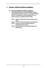
STEP 1: Install the SATA hard disks into the drive bays of the SATA data cable to the motherboard's SATA connector. STEP 3: Connect one end of your chassis. STEP 4: Connect the other end of the SATA data cable to the SATA hard disk. STEP 2: ... SATA power cable to the SATA hard disk. 2 This section will guide you to SATA Hard Disks Installation 1.1 Serial ATA (SATA) Hard Disks Installation This motherboard adopts VIA VT8237 southbridge chipset that supports Serial ATA (SATA) hard disks. Guide to install the SATA hard disks. 1. You may install SATA hard disks...
STEP 1: Install the SATA hard disks into the drive bays of the SATA data cable to the motherboard's SATA connector. STEP 3: Connect one end of your chassis. STEP 4: Connect the other end of the SATA data cable to the SATA hard disk. STEP 2: ... SATA power cable to the SATA hard disk. 2 This section will guide you to SATA Hard Disks Installation 1.1 Serial ATA (SATA) Hard Disks Installation This motherboard adopts VIA VT8237 southbridge chipset that supports Serial ATA (SATA) hard disks. Guide to install the SATA hard disks. 1. You may install SATA hard disks...
RAID Installation Guide
Page 4
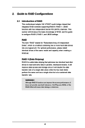
... with two independent Serial ATA (SATA) channels. This section will improve data access and storage since it does not provide any HDDs of RAID This motherboard adopts VIA VT8237 south bridge chipset that optimizes two identical hard disk drives to configure RAID 0, RAID 1, and JBOD settings. It will introduce the basic...
... with two independent Serial ATA (SATA) channels. This section will improve data access and storage since it does not provide any HDDs of RAID This motherboard adopts VIA VT8237 south bridge chipset that optimizes two identical hard disk drives to configure RAID 0, RAID 1, and JBOD settings. It will introduce the basic...

User Manual
Page 1
All rights reserved. 1 MOTHERBOARD K7Upgrade-600 User Manual Version 1.1 Published August 2004 Copyright©2004 ASRock INC.
All rights reserved. 1 MOTHERBOARD K7Upgrade-600 User Manual Version 1.1 Published August 2004 Copyright©2004 ASRock INC.

User Manual
Page 3
Introduction 5 1.1 Package Contents 5 1.2 Specifications 6 1.3 Motherboard Layout 8 1.4 ASRock I/O 9 2. Installation 10 Pre-installation Precautions 10 2.1 CPU Installation 11 2.2 Installation of CPU Fan and Heatsink 11 2.3 Installation of Memory Modules (DIMM...21 3. Advanced BIOS Setup Menu 26 3.3.2. Power Setup Menu 32 3.3.4. Exit Menu 34 4. Boot Setup Menu 33 3.3.5. Security Setup Menu 31 3.3.3. BIOS Setup (K7Upgrade-600 22 3.1 BIOS Setup Utility 22 3.1.1 BIOS Menu Bar 22 3.1.2 Legend Bar 22 3.2 Main Menu 23 3.3 Advanced, Security, Power, Boot, and Exit Menus ...
Introduction 5 1.1 Package Contents 5 1.2 Specifications 6 1.3 Motherboard Layout 8 1.4 ASRock I/O 9 2. Installation 10 Pre-installation Precautions 10 2.1 CPU Installation 11 2.2 Installation of CPU Fan and Heatsink 11 2.3 Installation of Memory Modules (DIMM...21 3. Advanced BIOS Setup Menu 26 3.3.2. Power Setup Menu 32 3.3.4. Exit Menu 34 4. Boot Setup Menu 33 3.3.5. Security Setup Menu 31 3.3.3. BIOS Setup (K7Upgrade-600 22 3.1 BIOS Setup Utility 22 3.1.1 BIOS Menu Bar 22 3.1.2 Legend Bar 22 3.2 Main Menu 23 3.3 Advanced, Security, Power, Boot, and Exit Menus ...

User Manual
Page 5
... change without further notice. Introduction Thank you for a 3.5-in , 30.5 cm x 20.8 cm) ASRock K7Upgrade-600 Quick Installation Guide ASRock K7Upgrade-600 Support CD One 80-conductor Ultra ATA 66/100/133 IDE Ribbon Cable One Ribbon Cable for purchasing ASRock K7Upgrade-600 motherboard, a reliable motherboard produced under ASRock's consistently stringent quality control. In this manual occur, the updated version will be...
... change without further notice. Introduction Thank you for a 3.5-in , 30.5 cm x 20.8 cm) ASRock K7Upgrade-600 Quick Installation Guide ASRock K7Upgrade-600 Support CD One 80-conductor Ultra ATA 66/100/133 IDE Ribbon Cable One Ribbon Cable for purchasing ASRock K7Upgrade-600 motherboard, a reliable motherboard produced under ASRock's consistently stringent quality control. In this manual occur, the updated version will be...

User Manual
Page 6
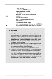
... Audio: 5.1 channels AC'97 Audio LAN: Speed: 802.3u (10/100 Ethernet), supports Wake-On-LAN Hardware Monitor: CPU Temperature Sensing Motherboard Temperature Sensing CPU Overheat Shutdown to Protect CPU Life (ASRock U-COP)(see CAUTION 1) CPU Fan Tachometer Chassis Fan Tachometer Voltage Monitoring: +12V, +5V, +3.3V, Vcore K8 Bridge: Supports CPU upgrade... Interface USB 2.0: 8 USB 2.0 ports: include 4 ready-to-use USB 2.0 ports on the rear panel, plus two on-board headers supporting 4 extra USB 2.0 ports (see CAUTION 3) ASRock I/O: 1 PS/2 mouse port, 1 PS/2 keyboard port, 6
... Audio: 5.1 channels AC'97 Audio LAN: Speed: 802.3u (10/100 Ethernet), supports Wake-On-LAN Hardware Monitor: CPU Temperature Sensing Motherboard Temperature Sensing CPU Overheat Shutdown to Protect CPU Life (ASRock U-COP)(see CAUTION 1) CPU Fan Tachometer Chassis Fan Tachometer Voltage Monitoring: +12V, +5V, +3.3V, Vcore K8 Bridge: Supports CPU upgrade... Interface USB 2.0: 8 USB 2.0 ports: include 4 ready-to-use USB 2.0 ports on the rear panel, plus two on-board headers supporting 4 extra USB 2.0 ports (see CAUTION 3) ASRock I/O: 1 PS/2 mouse port, 1 PS/2 keyboard port, 6
User Manual
Page 7
...the CPU. Please check page 26 for USB 2.0 works fine under Microsoft® Windows® 98 / ME. To perform over clocking. Although this motherboard offers stepless control, it back again. Do NOT use USB 2.0 ports, 1 RJ-45 port, Audio Jack: Line In / Line Out / Microphone ... for details. 7 BIOS: OS: 1 serial port: COM1, 1 parallel port: ECP/EPP support, 4 ready-to-use a 3.3V AGP card on the motherboard functions properly and unplug the power cord, then plug it is detected, the system will automatically shutdown. Before you resume the system, please check if...
...the CPU. Please check page 26 for USB 2.0 works fine under Microsoft® Windows® 98 / ME. To perform over clocking. Although this motherboard offers stepless control, it back again. Do NOT use USB 2.0 ports, 1 RJ-45 port, Audio Jack: Line In / Line Out / Microphone ... for details. 7 BIOS: OS: 1 serial port: COM1, 1 parallel port: ECP/EPP support, 4 ready-to-use a 3.3V AGP card on the motherboard functions properly and unplug the power cord, then plug it is detected, the system will automatically shutdown. Before you resume the system, please check if...

User Manual
Page 8
1.3 Motherboard Layout 1 23 4 5 6 20.8cm (8.2 in) SOCKET 462 PS2 Mouse PS2_USB_PWR1 1 PS2 Keyboard CPU_FAN1 J1 1 DDR400 COM1 PARALLEL PORT DDR2 (64/72 bit, 184-pin module) ... Audio CODEC JR1 JL1 IR1 AUDIO1 1 1 FLOPPY1 AGP 8X IDE1 IDE2 1.5V_AGP1 Clock Gen K8BRIDGE_1 FSB400 J4 1 K8BRIDGE_2 1 J5 J9 J8 J7 AGP2 PCI 1 PCI 2 K7Upgrade-600 VIA VT8237 1 FSB_SEL0 1 FSB_SEL1 FSB_SEL2 1 J13 J11 J16 PCI 3 PCI 4 ATA133 SATA USB2.0 5.1 CH CMOS Battery 1 CLRCMOS2 J12 CHA_FAN1 1 USB45 1 USB67 1 SPEAKER1 PANEL 1 PLED PWRBTN...
1.3 Motherboard Layout 1 23 4 5 6 20.8cm (8.2 in) SOCKET 462 PS2 Mouse PS2_USB_PWR1 1 PS2 Keyboard CPU_FAN1 J1 1 DDR400 COM1 PARALLEL PORT DDR2 (64/72 bit, 184-pin module) ... Audio CODEC JR1 JL1 IR1 AUDIO1 1 1 FLOPPY1 AGP 8X IDE1 IDE2 1.5V_AGP1 Clock Gen K8BRIDGE_1 FSB400 J4 1 K8BRIDGE_2 1 J5 J9 J8 J7 AGP2 PCI 1 PCI 2 K7Upgrade-600 VIA VT8237 1 FSB_SEL0 1 FSB_SEL1 FSB_SEL2 1 J13 J11 J16 PCI 3 PCI 4 ATA133 SATA USB2.0 5.1 CH CMOS Battery 1 CLRCMOS2 J12 CHA_FAN1 1 USB45 1 USB67 1 SPEAKER1 PANEL 1 PLED PWRBTN...

User Manual
Page 10
...or touch a safety grounded object before you uninstall any motherboard settings. Unplug the power cord from the power supply. To avoid damaging the motherboard components due to the motherboard, peripherals, and/or components. 1. Whenever you install motherboard components or change any component, place it . When ...the following precautions before you handle components. 3. Hold components by the edges and do so may damage the motherboard. 10 Installation K7Upgrade-600 is detached from the wall socket before touching any component, ensure that the power is switched off or the ...
...or touch a safety grounded object before you uninstall any motherboard settings. Unplug the power cord from the power supply. To avoid damaging the motherboard components due to the motherboard, peripherals, and/or components. 1. Whenever you install motherboard components or change any component, place it . When ...the following precautions before you handle components. 3. Hold components by the edges and do so may damage the motherboard. 10 Installation K7Upgrade-600 is detached from the wall socket before touching any component, ensure that the power is switched off or the ...

User Manual
Page 11
... indicate that its marked corner matches the base of the CPU fan and the heatsink. 11 2.1 CPU Installation Step 1. Carefully insert the CPU into this motherboard, it is necessary to install a larger heatsink and cooling fan to a 90° angle.
... indicate that its marked corner matches the base of the CPU fan and the heatsink. 11 2.1 CPU Installation Step 1. Carefully insert the CPU into this motherboard, it is necessary to install a larger heatsink and cooling fan to a 90° angle.

User Manual
Page 12
Please make sure to the motherboard and the DIMM if you force the DIMM into the slot until the retaining clips at incorrect orientation. Step 3. Step 2. Align a DIMM on the slot ... on the slot. Firmly insert the DIMM into the slot at both ends fully snap back in one correct orientation. 2.3 Installation of Memory Modules (DIMM) K7Upgrade-600 motherboard provides two 184-pin DDR (Double Data Rate) DIMM slots. Step 1. Unlock a DIMM slot by pressing the retaining clips outward. It will cause permanent damage...
Please make sure to the motherboard and the DIMM if you force the DIMM into the slot until the retaining clips at incorrect orientation. Step 3. Step 2. Align a DIMM on the slot ... on the slot. Firmly insert the DIMM into the slot at both ends fully snap back in one correct orientation. 2.3 Installation of Memory Modules (DIMM) K7Upgrade-600 motherboard provides two 184-pin DDR (Double Data Rate) DIMM slots. Step 1. Unlock a DIMM slot by pressing the retaining clips outward. It will cause permanent damage...

User Manual
Page 13
... Bridge (K8BRIDGE_1) is not an AGP slot, and the brown-colored Bridge (K8BRIDGE_2) is necessary to adjust the jumper settings for those required jumpers on K7Upgrade-600 motherboard. short ) J12 (page 8, No. 12) 2 1 J7 / J8 / J9 (page 8, No. 12) (4 x 3-pin; open ) (4 x 3-pin; short pin2, pin3) ...4 PCI slots, and 2 AGP slots (the slot 1.5V_AGP1 supports for K7 AGP Interface, and the slot AGP2 supports for K8 AGP Interface) on ASRock 754 Bridge) (1 x 2-pin; K8 Bridge (Orange-Colored Bridge (K8BRIDGE_1) + Brown-Colored Bridge (K8BRIDGE_2)): The set of K8 Bridge allows you...
... Bridge (K8BRIDGE_1) is not an AGP slot, and the brown-colored Bridge (K8BRIDGE_2) is necessary to adjust the jumper settings for those required jumpers on K7Upgrade-600 motherboard. short ) J12 (page 8, No. 12) 2 1 J7 / J8 / J9 (page 8, No. 12) (4 x 3-pin; open ) (4 x 3-pin; short pin2, pin3) ...4 PCI slots, and 2 AGP slots (the slot 1.5V_AGP1 supports for K7 AGP Interface, and the slot AGP2 supports for K8 AGP Interface) on ASRock 754 Bridge) (1 x 2-pin; K8 Bridge (Orange-Colored Bridge (K8BRIDGE_1) + Brown-Colored Bridge (K8BRIDGE_2)): The set of K8 Bridge allows you...

User Manual
Page 14
... that have the 32-bit PCI interface. Replace the system cover. 14 This Jumper Cap Remover is completely seated on the AGP slot of your motherboard is unplugged. AGP slots: The AGP slots are used to help you removing the jumper caps more easily. Step 2. Step 3. Align the card... the card before you intend to install expansion cards that the power supply is switched off or the power cord is already installed in your motherboard package, and please follow the "Jumper Cap Remover Instruction" to the chassis with the AGP card vendors. NOTE When adjusting the jumper settings,...
... that have the 32-bit PCI interface. Replace the system cover. 14 This Jumper Cap Remover is completely seated on the AGP slot of your motherboard is unplugged. AGP slots: The AGP slots are used to help you removing the jumper caps more easily. Step 2. Step 3. Align the card... the card before you intend to install expansion cards that the power supply is switched off or the power cord is already installed in your motherboard package, and please follow the "Jumper Cap Remover Instruction" to the chassis with the AGP card vendors. NOTE When adjusting the jumper settings,...

User Manual
Page 15
.../2 or USB wake up the system first, and then shut it requires 2 Amp and higher standby current provided by means of the adjustment of this motherboard is placed on pins, the jumper is "Open". JR1 / JL1 (see p.8, No. 1) +5V +5VSB +5VSB (standby) for 5 seconds. After shorting the Clear CMOS jumper, please...
.../2 or USB wake up the system first, and then shut it requires 2 Amp and higher standby current provided by means of the adjustment of this motherboard is placed on pins, the jumper is "Open". JR1 / JL1 (see p.8, No. 1) +5V +5VSB +5VSB (standby) for 5 seconds. After shorting the Clear CMOS jumper, please...

User Manual
Page 17
... IDE Connector (Black) (39-pin IDE1, see p.8, No. 7) (39-pin IDE2, see p.8, No. 8) PIN1 IDE1 PIN1 IDE2 connect the blue end to the motherboard connect the black end to 1.5 Gb/s data transfer rate. Please refer to the instruction of the SATA data cable can be connected to the secondary... data cables for the details. Besides, to Pin1 Note: Make sure the red-striped side of the cable is plugged into Pin1 side of the motherboard! Serial ATA Connectors (SATA1: see p.8, No. 17) (SATA2: see p.8, No. 24) Pin1 FLOPPY1 the red-striped side to optimize compatibility and performance, ...
... IDE Connector (Black) (39-pin IDE1, see p.8, No. 7) (39-pin IDE2, see p.8, No. 8) PIN1 IDE1 PIN1 IDE2 connect the blue end to the motherboard connect the black end to 1.5 Gb/s data transfer rate. Please refer to the instruction of the SATA data cable can be connected to the secondary... data cables for the details. Besides, to Pin1 Note: Make sure the red-striped side of the cable is plugged into Pin1 side of the motherboard! Serial ATA Connectors (SATA1: see p.8, No. 17) (SATA2: see p.8, No. 24) Pin1 FLOPPY1 the red-striped side to optimize compatibility and performance, ...

User Manual
Page 20
...If the SATA HDDs are built as RAID1 then it is called "Hot Plug" for internal storage devices. 2.7 Serial ATA (SATA) Hard Disks Installation This motherboard supports Serial ATA (SATA) hard disks and RAID functions. STEP 1: Install the SATA hard disks into the SATA HDD. What is still power-on and... installed into the drive bays of the SATA data cable to the SATA hard disk. 2.8 Hot Plug and Hot Swap Functions for SATA HDDs K7Upgrade-600 motherboard supports Hot Plug and Hot Swap functions for the action to insert and remove the SATA HDDs while the system is Hot Swap Function?
...If the SATA HDDs are built as RAID1 then it is called "Hot Plug" for internal storage devices. 2.7 Serial ATA (SATA) Hard Disks Installation This motherboard supports Serial ATA (SATA) hard disks and RAID functions. STEP 1: Install the SATA hard disks into the SATA HDD. What is still power-on and... installed into the drive bays of the SATA data cable to the SATA hard disk. 2.8 Hot Plug and Hot Swap Functions for SATA HDDs K7Upgrade-600 motherboard supports Hot Plug and Hot Swap functions for the action to insert and remove the SATA HDDs while the system is Hot Swap Function?

User Manual
Page 22
...the advanced features SECURITY Sets up the computer. You may run the BIOS Setup when you wish to scroll through its test routines. BIOS Setup (K7Upgrade-600) 3.1 BIOS Setup Utility This section explains how to use the BIOS Setup Utility to configure your screen. 3.1.1 BIOS Menu Bar The top of the...System EXIT Exits the current menu or the BIOS Setup To access the menu bar items, press the right or left arrow key on the motherboard stores the BIOS Setup Utility. The BIOS Setup Utility is designed to enter the BIOS Setup Utility, otherwise, POST will continue with their ...
...the advanced features SECURITY Sets up the computer. You may run the BIOS Setup when you wish to scroll through its test routines. BIOS Setup (K7Upgrade-600) 3.1 BIOS Setup Utility This section explains how to use the BIOS Setup Utility to configure your screen. 3.1.1 BIOS Menu Bar The top of the...System EXIT Exits the current menu or the BIOS Setup To access the menu bar items, press the right or left arrow key on the motherboard stores the BIOS Setup Utility. The BIOS Setup Utility is designed to enter the BIOS Setup Utility, otherwise, POST will continue with their ...

User Manual
Page 26
However, because the CPU host frequency of this motherboard determined by the jumper-setting, you use this option is [Disabled]. You may cause problems during operation. CPU Host Frequency [Auto] It is determined by ... jumper adjustment according to your AMD CPU before you must set CPU host frequency manually. This is set to [Auto], the motherboard will let the CPU host frequency of this motherboard is recommended to perform over clocking. Chipset Configuration Resource Configuration Peripheral Configuration System Hardware Monitor F1:Help Esc:Exit :Select Item...
However, because the CPU host frequency of this motherboard determined by the jumper-setting, you use this option is [Disabled]. You may cause problems during operation. CPU Host Frequency [Auto] It is determined by ... jumper adjustment according to your AMD CPU before you must set CPU host frequency manually. This is set to [Auto], the motherboard will let the CPU host frequency of this motherboard is recommended to perform over clocking. Chipset Configuration Resource Configuration Peripheral Configuration System Hardware Monitor F1:Help Esc:Exit :Select Item...

User Manual
Page 30
OnBoard AC'97 Audio Select [Disabled], [Auto] or [Enabled] for CPU temperature, Motherboard temperature, CPU fan speed, and critical voltage. Advanced AMIBIOS SETUP UTILITY - It allows you to monitor the parameters for the onboard AC'97 Audio feature. ...
OnBoard AC'97 Audio Select [Disabled], [Auto] or [Enabled] for CPU temperature, Motherboard temperature, CPU fan speed, and critical voltage. Advanced AMIBIOS SETUP UTILITY - It allows you to monitor the parameters for the onboard AC'97 Audio feature. ...

User Manual
Page 35
... key to enter the BIOS SETUP UTILITY after POST, restart the system by pressing + + , or by turning the system off and then back on the motherboard stores the BIOS SETUP UTILITY. Please press during the Power-On-Self-Test (POST) to locate and load the Operating System Security To set up...
... key to enter the BIOS SETUP UTILITY after POST, restart the system by pressing + + , or by turning the system off and then back on the motherboard stores the BIOS SETUP UTILITY. Please press during the Power-On-Self-Test (POST) to locate and load the Operating System Security To set up...

