User Manual
Page 7
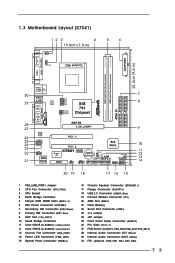
... FSB_SEL0 SiS 741 Chipset AGP 8X 1.5V_AGP1 ` ATA133 IDE2 IDE1 AUDIO CODEC AUDIO1 1 JR1 JL1 COM1 1 2MB BIOS PCI 1 PCI 2 SiS 963L K7S41 Super I/O IR1 AMR1 1 FSB400 DDR400 USB45 1 CMOS CLRCMOS1 Battery 5.1CH CLRCMOS2 FLOPPY1 USB 2.0 CHA_FAN1 PWR_LED1 1 PLED PWRBTN SPEAKER1 PANEL 1 1 1 ...HDLED RST 20 19 18 17 16 15 7 8 9 10 11 12 13 14 1 PS2_USB_PWR1 Jumper 2 CPU Fan Connector (CPU_FAN1) 3 CPU Socket 4 North Bridge Controller 5 184-pin DDR DIMM Slots (DDR 1- 2) 6 ATX Power Connector (ATXPWR1) 7 Secondary IDE Connector (IDE2, Black) 8 Primary IDE Connector...
... FSB_SEL0 SiS 741 Chipset AGP 8X 1.5V_AGP1 ` ATA133 IDE2 IDE1 AUDIO CODEC AUDIO1 1 JR1 JL1 COM1 1 2MB BIOS PCI 1 PCI 2 SiS 963L K7S41 Super I/O IR1 AMR1 1 FSB400 DDR400 USB45 1 CMOS CLRCMOS1 Battery 5.1CH CLRCMOS2 FLOPPY1 USB 2.0 CHA_FAN1 PWR_LED1 1 PLED PWRBTN SPEAKER1 PANEL 1 1 1 ...HDLED RST 20 19 18 17 16 15 7 8 9 10 11 12 13 14 1 PS2_USB_PWR1 Jumper 2 CPU Fan Connector (CPU_FAN1) 3 CPU Socket 4 North Bridge Controller 5 184-pin DDR DIMM Slots (DDR 1- 2) 6 ATX Power Connector (ATXPWR1) 7 Secondary IDE Connector (IDE2, Black) 8 Primary IDE Connector...
User Manual
Page 8
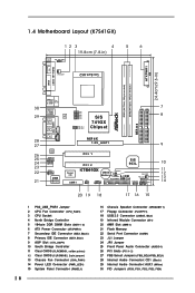
... PWR_LED1 1 PLED PWRBTN SPEAKER1 PANEL 1 1 1 HDLED RST 20 19 18 17 16 15 7 8 9 10 11 12 13 14 1 PS2_USB_PWR1 Jumper 2 CPU Fan Connector (CPU_FAN1) 3 CPU Socket 4 North Bridge Controller 5 184-pin DDR DIMM Slots (DDR 1- 2) 6 ATX Power Connector (ATXPWR1) 7 Secondary IDE Connector (IDE2, Black) 8 Primary IDE Connector (IDE1, Blue) 9 AGP Slot...
... PWR_LED1 1 PLED PWRBTN SPEAKER1 PANEL 1 1 1 HDLED RST 20 19 18 17 16 15 7 8 9 10 11 12 13 14 1 PS2_USB_PWR1 Jumper 2 CPU Fan Connector (CPU_FAN1) 3 CPU Socket 4 North Bridge Controller 5 184-pin DDR DIMM Slots (DDR 1- 2) 6 ATX Power Connector (ATXPWR1) 7 Secondary IDE Connector (IDE2, Black) 8 Primary IDE Connector (IDE1, Blue) 9 AGP Slot...

User Manual
Page 10
..., NEVER place your chassis to the motherboard, peripherals, and/or components. 10 Before you install or remove any motherboard settings. 1. Chapter 2 Installation K7S41 / K7S41GX is detached from the wall socket before touching any component, place it . Pre-installation Precautions Take note of the following precautions before you uninstall any component. 2. Unplug the...
..., NEVER place your chassis to the motherboard, peripherals, and/or components. 10 Before you install or remove any motherboard settings. 1. Chapter 2 Installation K7S41 / K7S41GX is detached from the wall socket before touching any component, place it . Pre-installation Precautions Take note of the following precautions before you uninstall any component. 2. Unplug the...

User Manual
Page 11
...need to spray thermal grease between the CPU and the heatsink to a 90o angle. 2.1 Step 1. Step 2. Carefully insert the CPU into the socket to The Socket Marked Corner The Socket Lever 2.2 Installation of the CPU fan and the heatsink. 11 Step 4. Make sure that the CPU and the heatsink are securely fastened and...connect the CPU fan to dissipate heat. When the CPU is locked. The CPU fits only in place. DO NOT force the CPU into the socket until it firmly on the side tab to support AMD Athlon XP / Duron CPU. It requires larger heatsink and cooling fan to the CPU_FAN connector...
...need to spray thermal grease between the CPU and the heatsink to a 90o angle. 2.1 Step 1. Step 2. Carefully insert the CPU into the socket to The Socket Marked Corner The Socket Lever 2.2 Installation of the CPU fan and the heatsink. 11 Step 4. Make sure that the CPU and the heatsink are securely fastened and...connect the CPU fan to dissipate heat. When the CPU is locked. The CPU fits only in place. DO NOT force the CPU into the socket until it firmly on the side tab to support AMD Athlon XP / Duron CPU. It requires larger heatsink and cooling fan to the CPU_FAN connector...