
User Manual
Page 3
... Contents 5 1.2 Specifications 6 1.3 Motherboard Layout 8 1.4 ASRock I/O PlusT M 9 2 Installation 10 2.1 Screw Holes 10 2.2 Pre-installation Precautions 10 2.3 CPU Installation 11 2.4 Installation of CPU Fan and Heatsink 11 2.5 Installation of Memory Modules (DIMM 12 2.6 Expansion Slots (PCI and A G P Slots 13 2.7 Jumpers Setup 14 2.8 Connectors 16 2.9 Serial ATA (SATA) Hard Disks Installation / RAID Configurations 19 2.10 Installing...
... Contents 5 1.2 Specifications 6 1.3 Motherboard Layout 8 1.4 ASRock I/O PlusT M 9 2 Installation 10 2.1 Screw Holes 10 2.2 Pre-installation Precautions 10 2.3 CPU Installation 11 2.4 Installation of CPU Fan and Heatsink 11 2.5 Installation of Memory Modules (DIMM 12 2.6 Expansion Slots (PCI and A G P Slots 13 2.7 Jumpers Setup 14 2.8 Connectors 16 2.9 Serial ATA (SATA) Hard Disks Installation / RAID Configurations 19 2.10 Installing...

User Manual
Page 5
You may find the latest memory and CPU support lists on page 23 for purchasing ASRock K7NF2-RAID motherboard, a reliable motherboard produced under ASRock's consistently stringent quality control. It delivers excellent performance with robust design conforming to ASRock's commitment to change without further notice. Chapter 1 and 2 of advanced BIOS setup is offered on ASRock website as well. More...
You may find the latest memory and CPU support lists on page 23 for purchasing ASRock K7NF2-RAID motherboard, a reliable motherboard produced under ASRock's consistently stringent quality control. It delivers excellent performance with robust design conforming to ASRock's commitment to change without further notice. Chapter 1 and 2 of advanced BIOS setup is offered on ASRock website as well. More...

User Manual
Page 6
...to 2 SATA devices at1.5Gb/s data transfer rate (Not Support "Hot Plug" function) Floppy Port: Supports up to protect CPU life (ASRock U-COP)(see CAUTION 3) ASRock I/O PlusT M: 1 PS/2 keyboard port, 1 PS/2 mouse port; 1 serial port: COM1; 1 parallel port: ECP/EPP support; ...1 RJ 45 port; 6 default USB 2.0 ports; Chassis temperature sensing; CPU fan tachometer; South Bridge: MCP-RAID, supports USB 2.0, ATA 133, SATA 1.5Gb/s Memory: 3D DR DIMM ...
...to 2 SATA devices at1.5Gb/s data transfer rate (Not Support "Hot Plug" function) Floppy Port: Supports up to protect CPU life (ASRock U-COP)(see CAUTION 3) ASRock I/O PlusT M: 1 PS/2 keyboard port, 1 PS/2 mouse port; 1 serial port: COM1; 1 parallel port: ECP/EPP support; ...1 RJ 45 port; 6 default USB 2.0 ports; Chassis temperature sensing; CPU fan tachometer; South Bridge: MCP-RAID, supports USB 2.0, ATA 133, SATA 1.5Gb/s Memory: 3D DR DIMM ...

User Manual
Page 8
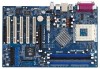
... USB5 USB45E 1 1 FSB_SEL0 FSB_SEL1 nnVFiUdoilratcCraeh42ip0s0et DDR400 Top: Line In Center: Line Out Bottom: Mic In ATXPWR1 CLRCMOS2 K7NF2-RAID CMOS Battery LAN PHY 1.5V_AGP1 PCI 1 AGP 8X PCI 2 MCP-RAID Chipset SATA2 SATA Super I/O SATA1 USB2.0 4Mb BIOS AUDIO CODEC AUDIO1 1 JR1 JL1 GAME1 1 PCI 3 ATA133 PCI...Blue) 18 Floppy Connector (FLOPPY1) 19 Game Connector (GAME1) 20 JR1 / JL1 Jumpers 21 Front Panel Audio Connector (AUDIO1) 22 Flash Memory 23 PCI Slots (PCI1- 5) 24 Clear CMOS Jumper (CLRCMOS2) 25 Internal Audio Connector: AUX1 (White) 26 Internal Audio Connector: CD1 ...
... USB5 USB45E 1 1 FSB_SEL0 FSB_SEL1 nnVFiUdoilratcCraeh42ip0s0et DDR400 Top: Line In Center: Line Out Bottom: Mic In ATXPWR1 CLRCMOS2 K7NF2-RAID CMOS Battery LAN PHY 1.5V_AGP1 PCI 1 AGP 8X PCI 2 MCP-RAID Chipset SATA2 SATA Super I/O SATA1 USB2.0 4Mb BIOS AUDIO CODEC AUDIO1 1 JR1 JL1 GAME1 1 PCI 3 ATA133 PCI...Blue) 18 Floppy Connector (FLOPPY1) 19 Game Connector (GAME1) 20 JR1 / JL1 Jumpers 21 Front Panel Audio Connector (AUDIO1) 22 Flash Memory 23 PCI Slots (PCI1- 5) 24 Clear CMOS Jumper (CLRCMOS2) 25 Internal Audio Connector: AUX1 (White) 26 Internal Audio Connector: CD1 ...

User Manual
Page 12
... need to disconnect power supply before adding or removing DIMMs or the system components. 2.5 Installation of Memory Modules (DIMM) K7NF2-RAID motherboard provides three 184-pin D DR (Double Data Rate) DIMM slots, and supports Dual Channel Memory Technology.To enable Dual-Channel mode, you force the DIMM into the slot at both ends fully...
... need to disconnect power supply before adding or removing DIMMs or the system components. 2.5 Installation of Memory Modules (DIMM) K7NF2-RAID motherboard provides three 184-pin D DR (Double Data Rate) DIMM slots, and supports Dual Channel Memory Technology.To enable Dual-Channel mode, you force the DIMM into the slot at both ends fully...

User Manual
Page 22
The Flash Memory on the motherboard stores the BIOS SETUP UTILITY.You may run the BIOS SETUP UTILITY when you start up the chipset features Exit To exit ...
The Flash Memory on the motherboard stores the BIOS SETUP UTILITY.You may run the BIOS SETUP UTILITY when you start up the chipset features Exit To exit ...

User Manual
Page 23
... System Date [17:00:09] [Thu 03/10/2005] BIOS Version : K7NF2-RAID BIOS P1.0 Processor Type : AMD Athlon(tm)64 Processor 3200+ Processor Speed : 2000 MHz L1 Cache Size : 128KB L2 Cache Size : 1024KB Total Memory DDR 1 DDR 2 DDR 3 : 512MB Dual-Channel Memory Mode : 256MB/166MHz (DDR333) : None : 256MB/166MHz (DDR333) Use [Enter...
... System Date [17:00:09] [Thu 03/10/2005] BIOS Version : K7NF2-RAID BIOS P1.0 Processor Type : AMD Athlon(tm)64 Processor 3200+ Processor Speed : 2000 MHz L1 Cache Size : 128KB L2 Cache Size : 1024KB Total Memory DDR 1 DDR 2 DDR 3 : 512MB Dual-Channel Memory Mode : 256MB/166MHz (DDR333) : None : 256MB/166MHz (DDR333) Use [Enter...

User Manual
Page 25
... and [Normal]. Configuration options: [Auto], [High], and [Normal]. TRP Use this to adjust TRP values. It will allow better tolerance for memory compatibility when it is [Disabled]. D RAM Voltage Use this to adjust the valuesfor D RAM Voltage. Configuration options: [Auto], and [Normal]....[7CLK], [8CLK], [9CLK], [10CLK], [11CLK], [12CLK], [13CLK], [14CLK], and [15CLK]. American Megatrends, Inc. Flexibility Option The default value of memory accessing. TRCD Use this option is set one of the standard values as listed: [133 MHz (DDR266)], [166 MHz (DDR333)], [200 MHz (DDR400)]....
... and [Normal]. Configuration options: [Auto], [High], and [Normal]. TRP Use this to adjust TRP values. It will allow better tolerance for memory compatibility when it is [Disabled]. D RAM Voltage Use this to adjust the valuesfor D RAM Voltage. Configuration options: [Auto], and [Normal]....[7CLK], [8CLK], [9CLK], [10CLK], [11CLK], [12CLK], [13CLK], [14CLK], and [15CLK]. American Megatrends, Inc. Flexibility Option The default value of memory accessing. TRCD Use this option is set one of the standard values as listed: [133 MHz (DDR266)], [166 MHz (DDR333)], [200 MHz (DDR400)]....

User Manual
Page 26
... leave this item to adjust the A G P Data Rate. It is recommended to select the type of Primary VG A in case of the PCI memory address range used for graphics memory. AGP Side Band Use this field at the default value unless the installed A G P card's specifications requires other sizes. AGP Data Rate Use...
... leave this item to adjust the A G P Data Rate. It is recommended to select the type of Primary VG A in case of the PCI memory address range used for graphics memory. AGP Side Band Use this field at the default value unless the installed A G P card's specifications requires other sizes. AGP Data Rate Use...

Quick Installation Guide
Page 2
... Front Panel Audio Connector (AUDIO1) 22 Flash Memory 23 PCI Slots (PCI1- 5) 24 Clear CMOS Jumper (CLRCMOS2) 25 Internal Audio Connector: AUX1 (White) 26 Internal Audio Connector: CD1 (Black) 27 ATX Power Connector (ATXPWR1) 28 Shared USB 2.0 Header (USB45E, Blue) 29 FSB Select Jumper (FSB_SEL1) 30 FSB Select Jumper (FSB_SEL0) 2 ASRock K7NF2-RAID Motherboard
... Front Panel Audio Connector (AUDIO1) 22 Flash Memory 23 PCI Slots (PCI1- 5) 24 Clear CMOS Jumper (CLRCMOS2) 25 Internal Audio Connector: AUX1 (White) 26 Internal Audio Connector: CD1 (Black) 27 ATX Power Connector (ATXPWR1) 28 Shared USB 2.0 Header (USB45E, Blue) 29 FSB Select Jumper (FSB_SEL1) 30 FSB Select Jumper (FSB_SEL0) 2 ASRock K7NF2-RAID Motherboard

Quick Installation Guide
Page 4
... the latest memory and CPU support lists on ASRock website without notice. ASRock website http://www.asrock.com 1.1 Package Contents ASRock K7NF2-RAID Motherboard (ATX Form Factor: 12.0-in x 7.8-in, 30.5 cm x 19.8 cm) ASRock K7NF2-RAID Quick Installation Guide ASRock K7NF2-RAID Support CD One 80-conductor Ultra ATA 66/100/133 IDE Ribbon Cable One Ribbon Cable for purchasing ASRock K7NF2-RAID motherboard, a reliable...
... the latest memory and CPU support lists on ASRock website without notice. ASRock website http://www.asrock.com 1.1 Package Contents ASRock K7NF2-RAID Motherboard (ATX Form Factor: 12.0-in x 7.8-in, 30.5 cm x 19.8 cm) ASRock K7NF2-RAID Quick Installation Guide ASRock K7NF2-RAID Support CD One 80-conductor Ultra ATA 66/100/133 IDE Ribbon Cable One Ribbon Cable for purchasing ASRock K7NF2-RAID motherboard, a reliable...
Quick Installation Guide
Page 5
...for 3 DDR DIMM slots, Max. 3GB; Audio Jack: Line Out / Line In / Microphone English 5 ASRock K7NF2-RAID Motherboard CPU fan tachometer; CPU overheat shutdown to protect CPU life (ASRock U-COP)(see CAUTION 3) ASRock I/O PlusTM: 1 PS/2 keyboard port, 1 PS/2 mouse port; 1 serial port: COM1; 1 parallel ... Speed: 802.3u (10/100 Ethernet), supports Wake-On-LAN Hardware Monitor: CPU temperature sensing; South Bridge: MCP-RAID, supports USB 2.0, ATA 133, SATA 1.5Gb/s Memory: 3 DDR DIMM slots: DDR1, DDR2, and DDR3 PC2100 (DDR266) / PC2700 (DDR333) / PC3200 (DDR400) for...
...for 3 DDR DIMM slots, Max. 3GB; Audio Jack: Line Out / Line In / Microphone English 5 ASRock K7NF2-RAID Motherboard CPU fan tachometer; CPU overheat shutdown to protect CPU life (ASRock U-COP)(see CAUTION 3) ASRock I/O PlusTM: 1 PS/2 keyboard port, 1 PS/2 mouse port; 1 serial port: COM1; 1 parallel ... Speed: 802.3u (10/100 Ethernet), supports Wake-On-LAN Hardware Monitor: CPU temperature sensing; South Bridge: MCP-RAID, supports USB 2.0, ATA 133, SATA 1.5Gb/s Memory: 3 DDR DIMM slots: DDR1, DDR2, and DDR3 PC2100 (DDR266) / PC2700 (DDR333) / PC3200 (DDR400) for...

Quick Installation Guide
Page 8
...the DIMM is properly seated. 8 ASRock K7NF2-RAID Motherboard English Unlock a DIMM slot by pressing the retaining clips outward. Installing a DIMM Please make sure to use two identical (the same brand, speed, size and chip-type) memory modules in one memory module, please install it on DDR1 ... the break on DDR1 and DDR3. Step 3. To enable Dual-Channel mode, you install 2 memory modules, please install them on the slot. 2.2 Installation of Memory Modules (DIMM) K7NF2-RAID motherboard provides three 184-pin DDR (Double Data Rate) DIMM slots, and supports Dual Channel...
...the DIMM is properly seated. 8 ASRock K7NF2-RAID Motherboard English Unlock a DIMM slot by pressing the retaining clips outward. Installing a DIMM Please make sure to use two identical (the same brand, speed, size and chip-type) memory modules in one memory module, please install it on DDR1 ... the break on DDR1 and DDR3. Step 3. To enable Dual-Channel mode, you install 2 memory modules, please install them on the slot. 2.2 Installation of Memory Modules (DIMM) K7NF2-RAID motherboard provides three 184-pin DDR (Double Data Rate) DIMM slots, and supports Dual Channel...

Quick Installation Guide
Page 16
...locate and double-click on the motherboard stores BIOS Setup Utility. For the detailed information about BIOS Setup, please refer to display the menus. 16 ASRock K7NF2-RAID Motherboard English The BIOS Setup program is a menu-driven program, which allows you to be user-friendly. 3. When you wish to select among... Setup after POST, please restart the system by pressing + + , or pressing the reset button on the system chassis. BIOS Information The Flash Memory on the file "ASSETUP.EXE" from the BIN folder in the Support CD to the User Manual (PDF file) contained in your CD-ROM ...
...locate and double-click on the motherboard stores BIOS Setup Utility. For the detailed information about BIOS Setup, please refer to display the menus. 16 ASRock K7NF2-RAID Motherboard English The BIOS Setup program is a menu-driven program, which allows you to be user-friendly. 3. When you wish to select among... Setup after POST, please restart the system by pressing + + , or pressing the reset button on the system chassis. BIOS Information The Flash Memory on the file "ASSETUP.EXE" from the BIN folder in the Support CD to the User Manual (PDF file) contained in your CD-ROM ...

