RAID Installation Guide
Page 1
NVIDIA BIOS RAID Installation Guide 2 1.1 Introduction to RAID 2 1.2 RAID Configurations Precautions 3 1.3 Installing Windows XP / XP 64-bit / Vista / Vista 64-bit With RAID Functions 5 1.3.1 Installing Windows XP / XP 64-bit With RAID Functions 5 1.3.2 Installing Windows Vista / Vista 64-bit With RAID Functions 7 1.4 Create Disk Array 8 2. NVIDIA RAID Installation Guide 1. NVIDIA Windows RAID Installation Guide 11 2.1 NVIDIA Windows RAID Installation Guide for Windows XP / XP 64-bit Users 11 2.2 NVIDIA Windows RAID Installation Guide for Windows Vista / Vista 64-bit Users 21 1
NVIDIA BIOS RAID Installation Guide 2 1.1 Introduction to RAID 2 1.2 RAID Configurations Precautions 3 1.3 Installing Windows XP / XP 64-bit / Vista / Vista 64-bit With RAID Functions 5 1.3.1 Installing Windows XP / XP 64-bit With RAID Functions 5 1.3.2 Installing Windows Vista / Vista 64-bit With RAID Functions 7 1.4 Create Disk Array 8 2. NVIDIA RAID Installation Guide 1. NVIDIA Windows RAID Installation Guide 11 2.1 NVIDIA Windows RAID Installation Guide for Windows XP / XP 64-bit Users 11 2.2 NVIDIA Windows RAID Installation Guide for Windows Vista / Vista 64-bit Users 21 1

RAID Installation Guide
Page 2
...WARNING!! RAID 1 (Data Mirroring) RAID 1 is called data striping that copies and maintains an identical image of using NVIDIA RAID Utility under BIOS environment. This section includes examples of data from one drive to set . For optimal performance, please install identical drives of the RAID 0 ...to the RAID functions your motherboard according to the SATA / SATAII HDDs amount you make a SATA / SATAII driver diskette, press to enter BIOS setup to a second drive. It will improve data access and storage since the disk array management software will double the data transfer rate of ...
...WARNING!! RAID 1 (Data Mirroring) RAID 1 is called data striping that copies and maintains an identical image of using NVIDIA RAID Utility under BIOS environment. This section includes examples of data from one drive to set . For optimal performance, please install identical drives of the RAID 0 ...to the RAID functions your motherboard according to the SATA / SATAII HDDs amount you make a SATA / SATAII driver diskette, press to enter BIOS setup to a second drive. It will improve data access and storage since the disk array management software will double the data transfer rate of ...

RAID Installation Guide
Page 5
... Driver diskette for WindowsXP 3. C. D. Generate RAID Driver diskette for WindowsXP64 4. Then you will start to boot your system. (There are two ASRock Support CD in the motherboard gift box pack, please choose the one for WindowsXP64 5. 1.3 Installing Windows® XP / XP 64-bit / ...the message on the list according to continue Please insert a floppy diskette into the floppy diskette. 5 STEP 1: Set Up BIOS. A. Insert the ASRock Support CD into your required item on the screen, "Generate Serial ATA driver diskette [YN]?", press . Select your optical drive...
... Driver diskette for WindowsXP 3. C. D. Generate RAID Driver diskette for WindowsXP64 4. Then you will start to boot your system. (There are two ASRock Support CD in the motherboard gift box pack, please choose the one for WindowsXP64 5. 1.3 Installing Windows® XP / XP 64-bit / ...the message on the list according to continue Please insert a floppy diskette into the floppy diskette. 5 STEP 1: Set Up BIOS. A. Insert the ASRock Support CD into your required item on the screen, "Generate Serial ATA driver diskette [YN]?", press . Select your optical drive...

RAID Installation Guide
Page 6
....) NOTE. NVIDIA RAID Driver (required) B. Please specify the first RAID driver and then specify again for RAID mode, you still need to the BIOS RAID installation guide part of the document in the following path in the Support CD: .. \ RAID Installation Guide 6 If you need to set... RAID mode. (There are as below: A. NVIDIA nForce Storage Controller (required) Please select A and B for Windows® XP / XP 64-bit in BIOS first. B. Then, please set the RAID configuration by using the Windows RAID installation guide part of Windows® setup, press F6 to set up "SATA...
....) NOTE. NVIDIA RAID Driver (required) B. Please specify the first RAID driver and then specify again for RAID mode, you still need to the BIOS RAID installation guide part of the document in the following path in the Support CD: .. \ RAID Installation Guide 6 If you need to set... RAID mode. (There are as below: A. NVIDIA nForce Storage Controller (required) Please select A and B for Windows® XP / XP 64-bit in BIOS first. B. Then, please set the RAID configuration by using the Windows RAID installation guide part of Windows® setup, press F6 to set up "SATA...

RAID Installation Guide
Page 7
...following path in our Support CD: (There are two ASRock Support CD in the motherboard gift box pack, please choose the one for proper configuration. A. Enter BIOS SETUP UTILITY Advanced screen IDE Configuration. Please refer to the BIOS RAID installation guide part of the document in the ... SATAII HDDs, you still need to check the RAID installation guide in the Support CD: .. \ RAID Installation Guide 7 STEP 1: Set Up BIOS. B. Before you start to configure RAID function, you need to set the RAID configuration by using the Windows RAID installation guide in the following ...
...following path in our Support CD: (There are two ASRock Support CD in the motherboard gift box pack, please choose the one for proper configuration. A. Enter BIOS SETUP UTILITY Advanced screen IDE Configuration. Please refer to the BIOS RAID installation guide part of the document in the ... SATAII HDDs, you still need to check the RAID installation guide in the Support CD: .. \ RAID Installation Guide 7 STEP 1: Set Up BIOS. B. Before you start to configure RAID function, you need to set the RAID configuration by using the Windows RAID installation guide in the following ...

RAID Installation Guide
Page 8
... mode, the below window appears. By default, RAID Mode is set it to Striping if you want to loading the OS. After adjusting the system BIOS to the steps of the system POST and boot process prior to create RAID 0. 1.4 Create Disk Array Power on your computer, wait until you see...
... mode, the below window appears. By default, RAID Mode is set it to Striping if you want to loading the OS. After adjusting the system BIOS to the steps of the system POST and boot process prior to create RAID 0. 1.4 Create Disk Array Power on your computer, wait until you see...

RAID Installation Guide
Page 9
... pressing the right-arrow key. The first disk in kilobytes, and affect how data is arranged on the disk. C. Move it from the RAID Config BIOS setup page appear in the Array Disks block. 9 The disks that you want to use as RAID array disks appear in the Free Disks block...
... pressing the right-arrow key. The first disk in kilobytes, and affect how data is arranged on the disk. C. Move it from the RAID Config BIOS setup page appear in the Array Disks block. 9 The disks that you want to use as RAID array disks appear in the Free Disks block...

RAID Installation Guide
Page 13
B. Create Array and the following : A. Boot to the steps of creating RAID 0. Please do the following screen will appear. 13 D. Click Next and the following screen shot will appear. the operation procedures are RAID enabled. Go to the system BIOS and make sure that the drives that you want to use are similar to Windows and launch the NVRAIDMAN application. C.
B. Create Array and the following : A. Boot to the steps of creating RAID 0. Please do the following screen will appear. 13 D. Click Next and the following screen shot will appear. the operation procedures are RAID enabled. Go to the system BIOS and make sure that the drives that you want to use are similar to Windows and launch the NVRAIDMAN application. C.

User Manual
Page 4
... 4 0 3.1 Introduction 40 3.1.1 BIOS Menu Bar 40 3.1.2 Navigation Keys 41 3.2 Main Screen 41 3.3 Smart Screen 42 3.4 Advanced Screen 43 3.4.1 CPU Configuration 44 3.4.2 Chipset Configuration 49 3.4.3 ACPI Configuration 51 3.4.4 IDE ...
... 4 0 3.1 Introduction 40 3.1.1 BIOS Menu Bar 40 3.1.2 Navigation Keys 41 3.2 Main Screen 41 3.3 Smart Screen 42 3.4 Advanced Screen 43 3.4.1 CPU Configuration 44 3.4.2 Chipset Configuration 49 3.4.3 ACPI Configuration 51 3.4.4 IDE ...
User Manual
Page 5
...guide to BIOS setup and information of the motherboard and step-by-step guide to change without further notice. You may find the latest VGA cards and CPU support lists on ASRock website without notice. www.asrock.com/support/index.asp 1.1 Package Contents ASRock K10N78M Motherboard (...Micro ATX Form Factor: 9.6-in x 7.5-in, 24.4 cm x 19.1 cm) ASRock K10N78M Quick Installation Guide ASRock K10N78M Support CD One 80-conductor Ultra ATA ...
...guide to BIOS setup and information of the motherboard and step-by-step guide to change without further notice. You may find the latest VGA cards and CPU support lists on ASRock website without notice. www.asrock.com/support/index.asp 1.1 Package Contents ASRock K10N78M Motherboard (...Micro ATX Form Factor: 9.6-in x 7.5-in, 24.4 cm x 19.1 cm) ASRock K10N78M Quick Installation Guide ASRock K10N78M Support CD One 80-conductor Ultra ATA ...

User Manual
Page 7
... Energy Saver (see CAUTION 7) - 6 x Ready-to 12.5% (see CAUTION 10) - Instant Boot - CPU Fan Tachometer - AMI Legal BIOS - ASRock OC Tuner (see CAUTION 14) - ASRock AM2 Boost: ASRock Patented Technology to boost memory performance up to -Use USB 2.0 Ports - 1 x RJ-45 LAN Port with LED (ACT/LINK LED and... SPEED LED) - Supports "Plug and Play" - ASRock U-COP (see CAUTION 12) - CPU/Chassis FAN connector - 24 pin ATX power connector - 4 pin 12V power connector - ACPI 1.1 Compliance Wake Up Events ...
... Energy Saver (see CAUTION 7) - 6 x Ready-to 12.5% (see CAUTION 10) - Instant Boot - CPU Fan Tachometer - AMI Legal BIOS - ASRock OC Tuner (see CAUTION 14) - ASRock AM2 Boost: ASRock Patented Technology to boost memory performance up to -Use USB 2.0 Ports - 1 x RJ-45 LAN Port with LED (ACT/LINK LED and... SPEED LED) - Supports "Plug and Play" - ASRock U-COP (see CAUTION 12) - CPU/Chassis FAN connector - 24 pin ATX power connector - 4 pin 12V power connector - ACPI 1.1 Compliance Wake Up Events ...
User Manual
Page 8
... the setting in our lab test. 7. This motherboard supports Dual Channel Memory Technology. ASRock website http://www.asrock.com 4. FCC, CE, WHQL * For detailed product information, please visit our website: http://www.asrock.com WARNING Please realize that there is a certain risk involved with 64-bit CPU,... there is supported depends on our website for details. 2. We are not responsible for the minimum hardware requirement and the passed 1080p Blu-ray (BD) / HD-DVD films in the BIOS,...
... the setting in our lab test. 7. This motherboard supports Dual Channel Memory Technology. ASRock website http://www.asrock.com 4. FCC, CE, WHQL * For detailed product information, please visit our website: http://www.asrock.com WARNING Please realize that there is a certain risk involved with 64-bit CPU,... there is supported depends on our website for details. 2. We are not responsible for the minimum hardware requirement and the passed 1080p Blu-ray (BD) / HD-DVD films in the BIOS,...
User Manual
Page 9
...the power cord, then plug it back again. Please visit our website for the operation procedures of Intelligent Energy Saver. ASRock website: http://www.asrock.com 12. This motherboard supports ASRock AM2 Boost overclocking technology for all CPU/DRAM configurations. 10. The voltage regulator can not guarantee the system stability for AM2...; environment. However, we can reduce the number of your system. 9 To use Intelligent Energy Saver function, please enable Cool 'n' Quiet option in the BIOS setup in the BIOS setup, the memory performance will automatically shutdown.
...the power cord, then plug it back again. Please visit our website for the operation procedures of Intelligent Energy Saver. ASRock website: http://www.asrock.com 12. This motherboard supports ASRock AM2 Boost overclocking technology for all CPU/DRAM configurations. 10. The voltage regulator can not guarantee the system stability for AM2...; environment. However, we can reduce the number of your system. 9 To use Intelligent Energy Saver function, please enable Cool 'n' Quiet option in the BIOS setup in the BIOS setup, the memory performance will automatically shutdown.
User Manual
Page 12
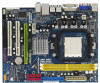
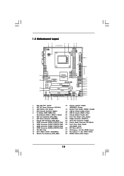
... 11 SATAII Connector (SATAII_1 (PORT 0), Red) (HD_AUDIO1, Lime) 12 SATAII Connector (SATAII_3 (PORT 2), Red) 26 PCI Slots (PCI1- 2) 13 SPI BIOS Chip 27 PCI Express x16 Slot (PCIE2, Green) 14 Clear CMOS Jumper (CLRCMOS1) 28 PCI Express x1 Slot (PCIE1, White) 15 Chassis Fan Connector (CHA_FAN1...(PORT 1) 28 27 26 PCIE1 Hybrid SLI Gigabit LAN Super I/O AUDIO CODEC HD_AUDIO1 1 CD1 COM1 1 FLOPPY1 PCIE2 K10N78M PCI1 RAID PCI2 LPT1 1 CMOS BATTERY 1 CLRCMOS1 IR1 1 USB8_9 1 USB6_7 1 RoHS 8Mb BIOS CHA_FAN1 SPEAKER1 1 PLED PWRBTN PANEL 1 1 HDLED RESET 10 11 12 13 14 15 16 17 25 24 23...
... 11 SATAII Connector (SATAII_1 (PORT 0), Red) (HD_AUDIO1, Lime) 12 SATAII Connector (SATAII_3 (PORT 2), Red) 26 PCI Slots (PCI1- 2) 13 SPI BIOS Chip 27 PCI Express x16 Slot (PCIE2, Green) 14 Clear CMOS Jumper (CLRCMOS1) 28 PCI Express x1 Slot (PCIE1, White) 15 Chassis Fan Connector (CHA_FAN1...(PORT 1) 28 27 26 PCIE1 Hybrid SLI Gigabit LAN Super I/O AUDIO CODEC HD_AUDIO1 1 CD1 COM1 1 FLOPPY1 PCIE2 K10N78M PCI1 RAID PCI2 LPT1 1 CMOS BATTERY 1 CLRCMOS1 IR1 1 USB8_9 1 USB6_7 1 RoHS 8Mb BIOS CHA_FAN1 SPEAKER1 1 PLED PWRBTN PANEL 1 1 HDLED RESET 10 11 12 13 14 15 16 17 25 24 23...

User Manual
Page 19
...the future. GeForce® Boost Step 1. For the proper installation procedures, please refer to enter BIOS setup. Connect the monitor cable to [Onboard], and save your system. Set up the BIOS option "Primary Graphics Display" to the correspondent connector on the PCI Express graphics card on the... I/O shield. Power off your BIOS change and exit BIOS setup. Switch your system. Please refer to our website for Hybrid SLITM GeForce® Boost and HybridPowerTM features are allowed...
...the future. GeForce® Boost Step 1. For the proper installation procedures, please refer to enter BIOS setup. Connect the monitor cable to [Onboard], and save your system. Set up the BIOS option "Primary Graphics Display" to the correspondent connector on the PCI Express graphics card on the... I/O shield. Power off your BIOS change and exit BIOS setup. Switch your system. Please refer to our website for Hybrid SLITM GeForce® Boost and HybridPowerTM features are allowed...

User Manual
Page 20
... from our support CD to your system. Restart your BIOS change and exit BIOS setup. Then you will find the Hybrid icon on your system. The default setting is in the following path of ASRock support CD: (There are two ASRock support CD in the motherboard gift box pack, please... Enter "Advanced" screen, and enter "Chipset Settings". Step 5. Boot into OS. Hybrid SLITM driver is in the following path of ASRock support CD: (There are two ASRock support CD in the motherboard gift box pack, please choose the one compatible PCI Express graphics card to [Onboard]. Step 6. Hybrid SLITM...
... from our support CD to your system. Restart your BIOS change and exit BIOS setup. Then you will find the Hybrid icon on your system. The default setting is in the following path of ASRock support CD: (There are two ASRock support CD in the motherboard gift box pack, please... Enter "Advanced" screen, and enter "Chipset Settings". Step 5. Boot into OS. Hybrid SLITM driver is in the following path of ASRock support CD: (There are two ASRock support CD in the motherboard gift box pack, please choose the one compatible PCI Express graphics card to [Onboard]. Step 6. Hybrid SLITM...

User Manual
Page 21
... (green). Then you will find the Hybrid icon on PCIE2 slot. Click the desktop. Boot your system is in the following path of ASRock support CD: (There are two ASRock support CD in the motherboard gift box pack, please choose the one for Windows® VistaTM / VistaTM 64-bit.) ..\Drivers\Hybrid SLI... 32 version, please visit our website for future update. Enter "Advanced" screen, and enter "Chipset Settings". For the proper installation procedures, please refer to enter BIOS setup. Then your system. Step 8. Click the desktop. Press to section "Expansion Slots". Step 4.
... (green). Then you will find the Hybrid icon on PCIE2 slot. Click the desktop. Boot your system is in the following path of ASRock support CD: (There are two ASRock support CD in the motherboard gift box pack, please choose the one for Windows® VistaTM / VistaTM 64-bit.) ..\Drivers\Hybrid SLI... 32 version, please visit our website for future update. Enter "Advanced" screen, and enter "Chipset Settings". For the proper installation procedures, please refer to enter BIOS setup. Then your system. Step 8. Click the desktop. Press to section "Expansion Slots". Step 4.

User Manual
Page 23
...icon in the Display Properties dialog that you have installed the onboard VGA driver and the add-on PCI Express VGA card driver to enter BIOS setup. D. F. If you can adjust the parameters of VGA/D-sub. And connect the other monitor cables to the corresponding connectors of the.../ XP 64-bit OS: Right click the desktop, choose "Properties", and select the "Settings" tab so that the value you do not adjust the BIOS setup, the default value of this motherboard. 4. Press to your system. If you select is no need to this motherboard. B. Connect the D-Sub ...
...icon in the Display Properties dialog that you have installed the onboard VGA driver and the add-on PCI Express VGA card driver to enter BIOS setup. D. F. If you can adjust the parameters of VGA/D-sub. And connect the other monitor cables to the corresponding connectors of the.../ XP 64-bit OS: Right click the desktop, choose "Properties", and select the "Settings" tab so that the value you do not adjust the BIOS setup, the default value of this motherboard. 4. Press to your system. If you select is no need to this motherboard. B. Connect the D-Sub ...

User Manual
Page 25
... function is available. 25 For Windows® XP / XP 64-bit OS Step 1: Set up BIOS. Step 2: Install HDMI audio driver to your system. Install "Onboard HDMI HD Audio Driver" from ASRock Support CD to your system manually. For Windows® VistaTM / VistaTM 64-bit OS Step 1: Set... up BIOS. Set the option "OnBoard HDMI HD Audio" to set up your system. Step 2: Enter Windows® ...
... function is available. 25 For Windows® XP / XP 64-bit OS Step 1: Set up BIOS. Step 2: Install HDMI audio driver to your system. Install "Onboard HDMI HD Audio Driver" from ASRock Support CD to your system manually. For Windows® VistaTM / VistaTM 64-bit OS Step 1: Set... up BIOS. Set the option "OnBoard HDMI HD Audio" to set up your system. Step 2: Enter Windows® ...

User Manual
Page 26
... to enable (see p.12, No. 14) 1_2 2_3 Default Clear CMOS Note: CLRCMOS1 allows you do not clear the CMOS right after you update the BIOS. Clear CMOS Jumper (CLRCMOS1) (see p.12, No. 1) +5V +5VSB +5VSB (standby) for 5 seconds. Jumper Setting PS2_USB_PW1 1_2 2_3 Short pin2, pin3 to clear the...and system setup parameters. The data in CMOS. To clear and reset the system parameters to clear the CMOS when you just finish updating the BIOS, you must boot up events. If you need to default setup, please turn off the computer and unplug the power cord from the power ...
... to enable (see p.12, No. 14) 1_2 2_3 Default Clear CMOS Note: CLRCMOS1 allows you do not clear the CMOS right after you update the BIOS. Clear CMOS Jumper (CLRCMOS1) (see p.12, No. 1) +5V +5VSB +5VSB (standby) for 5 seconds. Jumper Setting PS2_USB_PW1 1_2 2_3 Short pin2, pin3 to clear the...and system setup parameters. The data in CMOS. To clear and reset the system parameters to clear the CMOS when you just finish updating the BIOS, you must boot up events. If you need to default setup, please turn off the computer and unplug the power cord from the power ...


