User Manual
Page 2
... (including damages for loss of profits, loss of business, loss of data, interruption of business and the like), even if ASRock has been advised of the possibility of such damages arising from any interference received, including interference that may cause undesired operation. Disclaimer... fitness for a particular purpose. With respect to the contents of this motherboard contains Perchlorate, a toxic substance controlled in advance. CALIFORNIA, USA ONLY The Lithium battery adopted on this manual, ASRock does not provide warranty of any means, except duplication of documentation by ...
... (including damages for loss of profits, loss of business, loss of data, interruption of business and the like), even if ASRock has been advised of the possibility of such damages arising from any interference received, including interference that may cause undesired operation. Disclaimer... fitness for a particular purpose. With respect to the contents of this motherboard contains Perchlorate, a toxic substance controlled in advance. CALIFORNIA, USA ONLY The Lithium battery adopted on this manual, ASRock does not provide warranty of any means, except duplication of documentation by ...
User Manual
Page 3
... With RAID Functions 30 2.14.2 Installing Windows® VistaTM / VistaTM 64-bit With RAID Functions 31 2.15 Untied Overclocking Technology 32 3 . Introduction 5 1.1 Package Contents 5 1.2 Specifications 6 1.3 Motherboard Layout 10 1.4 I/O Panel 11 2 .
... With RAID Functions 30 2.14.2 Installing Windows® VistaTM / VistaTM 64-bit With RAID Functions 31 2.15 Untied Overclocking Technology 32 3 . Introduction 5 1.1 Package Contents 5 1.2 Specifications 6 1.3 Motherboard Layout 10 1.4 I/O Panel 11 2 .
User Manual
Page 5
... CD. You may find the latest VGA cards and CPU support lists on ASRock website without notice. www.asrock.com/support/index.asp 1.1 Package Contents ASRock K10N78D Motherboard (ATX Form Factor: 12.0-in x 7.5-in, 30.5 cm x 19.1 cm) ASRock K10N78D Quick Installation Guide ASRock K10N78D Support CD One 80-conductor Ultra ATA 66/100/133 IDE Ribbon Cable Two...
... CD. You may find the latest VGA cards and CPU support lists on ASRock website without notice. www.asrock.com/support/index.asp 1.1 Package Contents ASRock K10N78D Motherboard (ATX Form Factor: 12.0-in x 7.5-in, 30.5 cm x 19.1 cm) ASRock K10N78D Quick Installation Guide ASRock K10N78D Support CD One 80-conductor Ultra ATA 66/100/133 IDE Ribbon Cable Two...
User Manual
Page 8
..., please read "Untied Overclocking Technology" on page 15 for the operation procedures of your system by overclocking. ASRock website http://www.asrock.com 4. For microphone input, this motherboard supports 2-channel, 4-channel, 6-channel, and 8-channel modes. Before installing SATAII hard disk to SATAII mode.... should be less than 4GB for the reservation for details. 2. Due to the components and devices of ASRock OC Tuner. For audio output, this motherboard supports both stereo and mono modes. Overclocking may affect your system stability, or even cause damage to the...
..., please read "Untied Overclocking Technology" on page 15 for the operation procedures of your system by overclocking. ASRock website http://www.asrock.com 4. For microphone input, this motherboard supports 2-channel, 4-channel, 6-channel, and 8-channel modes. Before installing SATAII hard disk to SATAII mode.... should be less than 4GB for the reservation for details. 2. Due to the components and devices of ASRock OC Tuner. For audio output, this motherboard supports both stereo and mono modes. Overclocking may affect your system stability, or even cause damage to the...

User Manual
Page 9
... performance. While CPU overheat is a BIOS flash utility embedded in advance. To improve heat dissipation, remember to access ASRock Instant Flash. This motherboard supports ASRock AM2 Boost overclocking technology for the operation procedures of the system or damage the CPU. 12. If you enable this... when you adopt. To use FAT32/16/12 file system. 11. Just launch this motherboard offers stepless control, it is enabled, it back again. ASRock website: http://www.asrock.com 10. Featuring an advanced proprietary hardware and software design, Intelligent Energy Saver is able...
... performance. While CPU overheat is a BIOS flash utility embedded in advance. To improve heat dissipation, remember to access ASRock Instant Flash. This motherboard supports ASRock AM2 Boost overclocking technology for the operation procedures of the system or damage the CPU. 12. If you enable this... when you adopt. To use FAT32/16/12 file system. 11. Just launch this motherboard offers stepless control, it is enabled, it back again. ASRock website: http://www.asrock.com 10. Featuring an advanced proprietary hardware and software design, Intelligent Energy Saver is able...
User Manual
Page 10
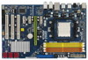
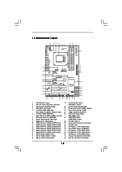
...PCIE1, White) 17 USB 2.0 Header (USB10_11, Blue) 34 Chassis Fan Connector (CHA_FAN1) 18 USB 2.0 Header (USB8_9, Blue) 35 CPU Fan Connector (CPU_FAN1) 10 1.3 Motherboard Layout PS2 Mouse PS2 Keyboard 1 23 4 19.1cm (7.5-in) 5 6 1 PS2_USB_PW1 FSB2.6GHz HT3.0 ATX12V1 7 AT X P W R 1 Dual Channel Coaxial Optical ... 28 27 26 25 Top: LINE IN Center: FRONT Bottom: MIC IN CHA_FAN1 CPU_FAN1 Phenom II AM2+/AM3 LAN PCIE1 PHY PCIE2 K10N78D PCIE3 PCI Express 2.0 CMOS BATTERY Super I/O CD1 AUDIO CODEC HDMI_SPDIF1 1 HD_AUDIO1 FLOPPY1 1 PCIE4 8Mb BIOS 1 CLRCMOS1 PCI1 RoHS PCI2...
...PCIE1, White) 17 USB 2.0 Header (USB10_11, Blue) 34 Chassis Fan Connector (CHA_FAN1) 18 USB 2.0 Header (USB8_9, Blue) 35 CPU Fan Connector (CPU_FAN1) 10 1.3 Motherboard Layout PS2 Mouse PS2 Keyboard 1 23 4 19.1cm (7.5-in) 5 6 1 PS2_USB_PW1 FSB2.6GHz HT3.0 ATX12V1 7 AT X P W R 1 Dual Channel Coaxial Optical ... 28 27 26 25 Top: LINE IN Center: FRONT Bottom: MIC IN CHA_FAN1 CPU_FAN1 Phenom II AM2+/AM3 LAN PCIE1 PHY PCIE2 K10N78D PCIE3 PCI Express 2.0 CMOS BATTERY Super I/O CD1 AUDIO CODEC HDMI_SPDIF1 1 HD_AUDIO1 FLOPPY1 1 PCIE4 8Mb BIOS 1 CLRCMOS1 PCI1 RoHS PCI2...

User Manual
Page 13
...place your chassis to ensure that comes with the component. 5. 2. Before you install the motherboard, study the configuration of the following precautions before you uninstall any motherboard settings. Before you install motherboard components or change any component, place it . Unplug the power cord from the power ...switched off or the power cord is an ATX form factor (12.0-in x 7.5-in the bag that the motherboard fits into the screw holes to secure the motherboard to use a grounded wrist strap or touch a safety grounded object before you install or remove any component. 2....
...place your chassis to ensure that comes with the component. 5. 2. Before you install the motherboard, study the configuration of the following precautions before you uninstall any motherboard settings. Before you install motherboard components or change any component, place it . Unplug the power cord from the power ...switched off or the power cord is an ATX form factor (12.0-in x 7.5-in the bag that the motherboard fits into the screw holes to secure the motherboard to use a grounded wrist strap or touch a safety grounded object before you install or remove any component. 2....
User Manual
Page 14
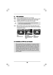
... down the socket lever to a 90o angle. Unlock the socket by lifting the lever up to secure the CPU. Carefully insert the CPU into this motherboard, it fits in one correct orientation.
... down the socket lever to a 90o angle. Unlock the socket by lifting the lever up to secure the CPU. Carefully insert the CPU into this motherboard, it fits in one correct orientation.

User Manual
Page 15
...the Dual Channel Memory Configuration Table below. If a pair of memory modules is NOT installed in all four slots. 1. otherwise, this motherboard, it is unable to install four DDR2 DIMMs for dual channel configuration, and please install identical DDR2 DIMMs in the same Dual Channel..., for optimal compatibility and reliability, it is unable to install them either in the set of Memory Modules (DIMM) This motherboard provides four 240-pin DDR2 (Double Data Rate 2) DIMM slots, and supports Dual Channel Memory Technology. Dual Channel Memory Configurations DDRII_1 DDRII_2...
...the Dual Channel Memory Configuration Table below. If a pair of memory modules is NOT installed in all four slots. 1. otherwise, this motherboard, it is unable to install four DDR2 DIMMs for dual channel configuration, and please install identical DDR2 DIMMs in the same Dual Channel..., for optimal compatibility and reliability, it is unable to install them either in the set of Memory Modules (DIMM) This motherboard provides four 240-pin DDR2 (Double Data Rate 2) DIMM slots, and supports Dual Channel Memory Technology. Dual Channel Memory Configurations DDRII_1 DDRII_2...

User Manual
Page 16
... before adding or removing DIMMs or the system components. Unlock a DIMM slot by pressing the retaining clips outward. Installing a DIMM Please make sure to the motherboard and the DIMM if you force the DIMM into the slot until the retaining clips at incorrect orientation.
... before adding or removing DIMMs or the system components. Unlock a DIMM slot by pressing the retaining clips outward. Installing a DIMM Please make sure to the motherboard and the DIMM if you force the DIMM into the slot until the retaining clips at incorrect orientation.

User Manual
Page 17
... 1. Before installing the expansion card, please make necessary hardware settings for PCI Express cards with screws. Remove the system unit cover (if your motherboard is used for later use . Step 3. Keep the screws for PCI Express cards with the slot and press firmly until the card is completely... seated on this motherboard. Replace the system cover. 17 PCI slots: PCI slots are 3 PCI slots and 4 PCI Express slots on the slot. Green) is already installed...
... 1. Before installing the expansion card, please make necessary hardware settings for PCI Express cards with screws. Remove the system unit cover (if your motherboard is used for later use . Step 3. Keep the screws for PCI Express cards with the slot and press firmly until the card is completely... seated on this motherboard. Replace the system cover. 17 PCI slots: PCI slots are 3 PCI slots and 4 PCI Express slots on the slot. Green) is already installed...

User Manual
Page 19
... jumpers. Placing jumper caps over these headers and connectors. Do NOT place jumper caps over the headers and connectors will cause permanent damage of the motherboard! • Floppy Connector (33-pin FLOPPY1) (see p.10, No. 10) SATAII_6 (PORT 5) SATAII_5 (PORT 4) SATAII_4 (PORT 3) SATAII_3 (PORT 2) ...SATA data cables for the details. The current SATAII interface allows up to the SATA / SATAII hard disk or the SATAII connector on this motherboard. 19 SATAII_2 (PORT 1) SATAII_1 (PORT 0) Serial ATA (SATA) Data Cable (Optional) Either end of the SATA data cable can be ...
... jumpers. Placing jumper caps over these headers and connectors. Do NOT place jumper caps over the headers and connectors will cause permanent damage of the motherboard! • Floppy Connector (33-pin FLOPPY1) (see p.10, No. 10) SATAII_6 (PORT 5) SATAII_5 (PORT 4) SATAII_4 (PORT 3) SATAII_3 (PORT 2) ...SATA data cables for the details. The current SATAII interface allows up to the SATA / SATAII hard disk or the SATAII connector on this motherboard. 19 SATAII_2 (PORT 1) SATAII_1 (PORT 0) Serial ATA (SATA) Data Cable (Optional) Either end of the SATA data cable can be ...
User Manual
Page 20
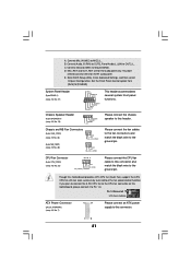
This connector allows you use AC'97 audio panel, please install it to the power connector on this motherboard. Each USB 2.0 header can support two USB 2.0 ports. High Definition Audio supports Jack Sensing, but the panel wire on the chassis must support HDA to ...
This connector allows you use AC'97 audio panel, please install it to the power connector on this motherboard. Each USB 2.0 header can support two USB 2.0 ports. High Definition Audio supports Jack Sensing, but the panel wire on the chassis must support HDA to ...
User Manual
Page 21
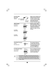
...) (see p.10 No. 34) GND +12V CHA_FAN_SPEED (3-pin NB_FAN1) (see p.10, No. 7) 12 24 Please connect an ATX power supply to this motherboard, please connect it to Pin 1-3. CPU Fan Connector (4-pin CPU_FAN1) (see p.10, No. 35) 4 3 2 1 GND +12V CPU_FAN_SPEED FAN_SPEED_CONTROL Please connect... the CPU fan cable to the ground pin. Though this connector and match the black wire to this motherboard provides 4-Pin CPU fan (Quiet Fan) support, the 3-Pin CPU fan still can work successfully even without the fan speed control function. ...
...) (see p.10 No. 34) GND +12V CHA_FAN_SPEED (3-pin NB_FAN1) (see p.10, No. 7) 12 24 Please connect an ATX power supply to this motherboard, please connect it to Pin 1-3. CPU Fan Connector (4-pin CPU_FAN1) (see p.10, No. 35) 4 3 2 1 GND +12V CPU_FAN_SPEED FAN_SPEED_CONTROL Please connect... the CPU fan cable to the ground pin. Though this connector and match the black wire to this motherboard provides 4-Pin CPU fan (Quiet Fan) support, the 3-Pin CPU fan still can work successfully even without the fan speed control function. ...

User Manual
Page 22
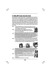
...) C. Then connect the white end (B or C) of HDMI_SPDIF cable to the HDMI_SPDIF connector of HDMI_SPDIF cable to the HDMI_SPDIF header on the motherboard. Though this connector. Please connect the black end (A) of HDMI VGA card. Failing to this header. Please connect the HDMI_SPDIF connector of HDMI... a traditional 20-pin ATX power supply. A. HDMI_SPDIF header, providing SPDIF audio output to HDMI VGA card, allows the system to this motherboard provides 24-pin ATX power connector, 12 24 it is necessary to connect a power supply with ATX 12V plug to connect HDMI Digital ...
...) C. Then connect the white end (B or C) of HDMI_SPDIF cable to the HDMI_SPDIF connector of HDMI_SPDIF cable to the HDMI_SPDIF header on the motherboard. Though this connector. Please connect the black end (A) of HDMI VGA card. Failing to this header. Please connect the HDMI_SPDIF connector of HDMI... a traditional 20-pin ATX power supply. A. HDMI_SPDIF header, providing SPDIF audio output to HDMI VGA card, allows the system to this motherboard provides 24-pin ATX power connector, 12 24 it is necessary to connect a power supply with ATX 12V plug to connect HDMI Digital ...
User Manual
Page 23
... header and HDMI_SPDIF cable connectors, please refer to the HDMI_SPDIF header (HDMI_SPDIF1, yellow, see page 10, No. 25) on this motherboard and the HDMI VGA card. Please choose the appropriate white end according to the HDMI_SPDIF connector of HDMI_SPDIF cable to page 22. white... card, allows the system to connect HDMI Digital TV/projector/ LCD devices. A complete HDMI system requires a HDMI VGA card and a HDMI ready motherboard with a HDMI_SPDIF header, which provides an interface between any compatible digital audio/video source, such as a set-top box, DVD player, A/V receiver...
... header and HDMI_SPDIF cable connectors, please refer to the HDMI_SPDIF header (HDMI_SPDIF1, yellow, see page 10, No. 25) on this motherboard and the HDMI VGA card. Please choose the appropriate white end according to the HDMI_SPDIF connector of HDMI_SPDIF cable to page 22. white... card, allows the system to connect HDMI Digital TV/projector/ LCD devices. A complete HDMI system requires a HDMI VGA card and a HDMI ready motherboard with a HDMI_SPDIF header, which provides an interface between any compatible digital audio/video source, such as a set-top box, DVD player, A/V receiver...
User Manual
Page 25
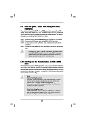
... JBOD function, you need to install 4 SATA / SATAII hard disks. 2.10 Hot Plug and Hot Swap Functions for SATA / SATAII HDDs This motherboard supports Hot Plug and Hot Swap functions for SATA host controllers developed thru a joint industry effort. AHCI also provides usability enhancements such as RAID1 or... install SATA / SATAII hard disks on and in RAID / AHCI mode. 2.9 Serial ATA (SATA) / Serial ATAII (SATAII) Hard Disks Installation This motherboard adopts NVIDIA® nForce 720D chipset that it cannot perform Hot Plug if the OS has been installed into the drive bays of the SATA...
... JBOD function, you need to install 4 SATA / SATAII hard disks. 2.10 Hot Plug and Hot Swap Functions for SATA / SATAII HDDs This motherboard supports Hot Plug and Hot Swap functions for SATA host controllers developed thru a joint industry effort. AHCI also provides usability enhancements such as RAID1 or... install SATA / SATAII hard disks on and in RAID / AHCI mode. 2.9 Serial ATA (SATA) / Serial ATAII (SATAII) Hard Disks Installation This motherboard adopts NVIDIA® nForce 720D chipset that it cannot perform Hot Plug if the OS has been installed into the drive bays of the SATA...
User Manual
Page 26
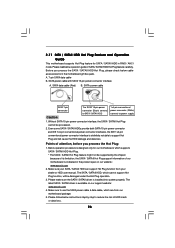
...IDE 1x4-pin conventional power connector interface is available on our website: www.asrock.com 2. Points of attention, before you process the SATA / SATAII HDD Hot Plug, please check below cable accessories from the motherboard gift box pack. Please make sure the SATA / SATAII driver is indicated ... loss. Please read below instructions step by the chipset because of its limitation, the SATA / SATAII Hot Plug support information of our motherboard is installed into system properly. Before you process the Hot Plug: 1. SATA power cable with SATA 15-pin power connector interface A. ...
...IDE 1x4-pin conventional power connector interface is available on our website: www.asrock.com 2. Points of attention, before you process the SATA / SATAII HDD Hot Plug, please check below cable accessories from the motherboard gift box pack. Please make sure the SATA / SATAII driver is indicated ... loss. Please read below instructions step by the chipset because of its limitation, the SATA / SATAII Hot Plug support information of our motherboard is installed into system properly. Before you process the Hot Plug: 1. SATA power cable with SATA 15-pin power connector interface A. ...

User Manual
Page 27
... the SATA / SATAII HDD. Step 4 Connect SATA data cable to SATA / SATAII HDD. Step 1 Unplug SATA data cable from SATA / SATAII HDD side. 27 the motherboard's SATAII connector. Step 1 Please connect SATA power cable 1x4-pin end Step 2 Connect SATA data cable to (White) to the power supply 1x4-pin cable...
... the SATA / SATAII HDD. Step 4 Connect SATA data cable to SATA / SATAII HDD. Step 1 Unplug SATA data cable from SATA / SATAII HDD side. 27 the motherboard's SATAII connector. Step 1 Please connect SATA power cable 1x4-pin end Step 2 Connect SATA data cable to (White) to the power supply 1x4-pin cable...
User Manual
Page 28
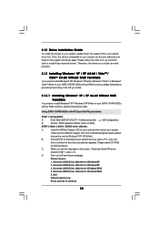
... 1: Set Up BIOS. Set the "SATA Operation Mode" option to boot your system. (There are two ASRock Support CD in the motherboard gift box pack, please choose the one for boot devices selection appears. A. Insert the ASRock Support CD into your optical drive to [IDE]. Please select CD-ROM as the boot device...
... 1: Set Up BIOS. Set the "SATA Operation Mode" option to boot your system. (There are two ASRock Support CD in the motherboard gift box pack, please choose the one for boot devices selection appears. A. Insert the ASRock Support CD into your optical drive to [IDE]. Please select CD-ROM as the boot device...

