User Manual
Page 3
Introduction 5 1.1 Package Contents 5 1.2 Specifications 6 1.3 Motherboard Layout 10 1.4 I/O Panel 11 2 . BIOS SETUP UTILITY 33 3.1 Introduction 33 3.1.1 BIOS Menu Bar 33 3.1.2 Navigation Keys 34 3.2 Main Screen 34 3 Contents 1 . Installation 13 Pre-installation Precautions 13 2.1 CPU Installation 14 2.2 Installation of CPU Fan and Heatsink ...
Introduction 5 1.1 Package Contents 5 1.2 Specifications 6 1.3 Motherboard Layout 10 1.4 I/O Panel 11 2 . BIOS SETUP UTILITY 33 3.1 Introduction 33 3.1.1 BIOS Menu Bar 33 3.1.2 Navigation Keys 34 3.2 Main Screen 34 3 Contents 1 . Installation 13 Pre-installation Precautions 13 2.1 CPU Installation 14 2.2 Installation of CPU Fan and Heatsink ...
User Manual
Page 5
...motherboard specifications and the BIOS software might be updated, the content of the motherboard and step-by-step guide to change without further notice. Chapter 3 and 4 contain the configuration guide to quality and endurance. 1. ASRock website http://www.asrock.com If you for...latest VGA cards and CPU support lists on ASRock website without notice. www.asrock.com/support/index.asp 1.1 Package Contents ASRock K10N78D Motherboard (ATX Form Factor: 12.0-in x 7.5-in, 30.5 cm x 19.1 cm) ASRock K10N78D Quick Installation Guide ASRock K10N78D Support CD One 80-conductor Ultra ATA 66/...
...motherboard specifications and the BIOS software might be updated, the content of the motherboard and step-by-step guide to change without further notice. Chapter 3 and 4 contain the configuration guide to quality and endurance. 1. ASRock website http://www.asrock.com If you for...latest VGA cards and CPU support lists on ASRock website without notice. www.asrock.com/support/index.asp 1.1 Package Contents ASRock K10N78D Motherboard (ATX Form Factor: 12.0-in x 7.5-in, 30.5 cm x 19.1 cm) ASRock K10N78D Quick Installation Guide ASRock K10N78D Support CD One 80-conductor Ultra ATA 66/...

User Manual
Page 7
...FAN connector - 24 pin ATX power connector - 4 pin 12V power connector - AMI Legal BIOS - Supports Smart BIOS Support CD - Instant Boot - CPU/Chassis/NB Fan Tachometer - Intelligent Energy Saver (see CAUTION 10) - ASRock Instant Flash (see CAUTION 9) - Voltage Monitoring: +12V, +5V, +3.3V, CPU ...® Windows® XP / XP Media Center / XP 64-bit / VistaTM / VistaTM 64-bit compliant Certifications - ASRock OC Tuner (see CAUTION 7) BIOS Feature - 8Mb AMI BIOS - FCC, CE, WHQL * For detailed product information, please visit our website: http://www...
...FAN connector - 24 pin ATX power connector - 4 pin 12V power connector - AMI Legal BIOS - Supports Smart BIOS Support CD - Instant Boot - CPU/Chassis/NB Fan Tachometer - Intelligent Energy Saver (see CAUTION 10) - ASRock Instant Flash (see CAUTION 9) - Voltage Monitoring: +12V, +5V, +3.3V, CPU ...® Windows® XP / XP Media Center / XP 64-bit / VistaTM / VistaTM 64-bit compliant Certifications - ASRock OC Tuner (see CAUTION 7) BIOS Feature - 8Mb AMI BIOS - FCC, CE, WHQL * For detailed product information, please visit our website: http://www...
User Manual
Page 8
...-bit CPU, there is no such limitation. 5. This motherboard supports Untied Overclocking Technology. Whether 1066MHz memory speed is a user-friendly ASRock overclocking tool which allows you to surveil your system by overclocking. Due to read "Untied Overclocking Technology" on page 15 for proper connection... http://www.asrock.com 4. For Windows® XP 64-bit and Windows® VistaTM 64-bit with overclocking, including adjusting the setting in the BIOS, applying Untied Overclocking Technology, or using the thirdparty overclocking tools. Please visit our website for USB 2.0 works ...
...-bit CPU, there is no such limitation. 5. This motherboard supports Untied Overclocking Technology. Whether 1066MHz memory speed is a user-friendly ASRock overclocking tool which allows you to surveil your system by overclocking. Due to read "Untied Overclocking Technology" on page 15 for proper connection... http://www.asrock.com 4. For Windows® XP 64-bit and Windows® VistaTM 64-bit with overclocking, including adjusting the setting in the BIOS, applying Untied Overclocking Technology, or using the thirdparty overclocking tools. Please visit our website for USB 2.0 works ...

User Manual
Page 9
...press key during the POST or press key to BIOS setup menu to improve efficiency when the CPU cores are idle. In other than the recommended CPU bus frequencies may cause the instability of output phases to access ASRock Instant Flash. With this function in advance. ... Please be applicative to disable this motherboard offers stepless control, it is enabled, it may choose to your BIOS only in Flash ROM. This motherboard supports ASRock AM2 Boost overclocking technology for the operation procedures of your system is unstable after AM2 Boost function is not recommended...
...press key during the POST or press key to BIOS setup menu to improve efficiency when the CPU cores are idle. In other than the recommended CPU bus frequencies may cause the instability of output phases to access ASRock Instant Flash. With this function in advance. ... Please be applicative to disable this motherboard offers stepless control, it is enabled, it may choose to your BIOS only in Flash ROM. This motherboard supports ASRock AM2 Boost overclocking technology for the operation procedures of your system is unstable after AM2 Boost function is not recommended...
User Manual
Page 10
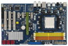
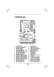
... 10 SATAII Connector (SATAII_6 (PORT 5), Red) 27 Internal Audio Connector: CD1 (Black) 11 SATAII Connector (SATAII_5 (PORT 4), Red) 28 SPI BIOS Chip 12 SATAII Connector (SATAII_4 (PORT 3), Red) 29 PCI Express x1 Slot (PCIE4, White) 13 SATAII Connector (SATAII_3 (PORT 2), Red) ...IN Center: FRONT Bottom: MIC IN CHA_FAN1 CPU_FAN1 Phenom II AM2+/AM3 LAN PCIE1 PHY PCIE2 K10N78D PCIE3 PCI Express 2.0 CMOS BATTERY Super I/O CD1 AUDIO CODEC HDMI_SPDIF1 1 HD_AUDIO1 FLOPPY1 1 PCIE4 8Mb BIOS 1 CLRCMOS1 PCI1 RoHS PCI2 NVIDIA nForce 720D Chipset SATAII_6 (PORT 5) SATAII_5 (PORT 4) ...
... 10 SATAII Connector (SATAII_6 (PORT 5), Red) 27 Internal Audio Connector: CD1 (Black) 11 SATAII Connector (SATAII_5 (PORT 4), Red) 28 SPI BIOS Chip 12 SATAII Connector (SATAII_4 (PORT 3), Red) 29 PCI Express x1 Slot (PCIE4, White) 13 SATAII Connector (SATAII_3 (PORT 2), Red) ...IN Center: FRONT Bottom: MIC IN CHA_FAN1 CPU_FAN1 Phenom II AM2+/AM3 LAN PCIE1 PHY PCIE2 K10N78D PCIE3 PCI Express 2.0 CMOS BATTERY Super I/O CD1 AUDIO CODEC HDMI_SPDIF1 1 HD_AUDIO1 FLOPPY1 1 PCIE4 8Mb BIOS 1 CLRCMOS1 PCI1 RoHS PCI2 NVIDIA nForce 720D Chipset SATAII_6 (PORT 5) SATAII_5 (PORT 4) ...

User Manual
Page 18
... "Short" when jumper cap is "Open". Note: To select +5VSB, it down before you update the BIOS. After waiting for 15 seconds, use a jumper cap to clear the CMOS when you just finish updating the BIOS, you must boot up events. However, please do not clear the CMOS right after you do...
... "Short" when jumper cap is "Open". Note: To select +5VSB, it down before you update the BIOS. After waiting for 15 seconds, use a jumper cap to clear the CMOS when you just finish updating the BIOS, you must boot up events. However, please do not clear the CMOS right after you do...
User Manual
Page 21
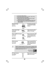
... 3-Pin Fan Installation ATX Power Connector (24-pin ATXPWR1) (see p.10 No. 20) GND +12V NB_FAN_SPEED This header accommodates several system front panel functions. Enter BIOS Setup Utility. MIC_RET and OUT_RET are for AC'97 audio panel. System Panel Header (9-pin PANEL1) (see p.10, No. 21) Chassis Speaker Header (4-pin SPEAKER...
... 3-Pin Fan Installation ATX Power Connector (24-pin ATXPWR1) (see p.10 No. 20) GND +12V NB_FAN_SPEED This header accommodates several system front panel functions. Enter BIOS Setup Utility. MIC_RET and OUT_RET are for AC'97 audio panel. System Panel Header (9-pin PANEL1) (see p.10, No. 21) Chassis Speaker Header (4-pin SPEAKER...
User Manual
Page 28
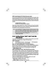
...174; XP / XP 64-bit / VistaTM / VistaTM 64-bit Without RAID Functions If you want to your system. (There are two ASRock Support CD in the motherboard gift box pack, please choose the one for WindowsXP64 5. Then, the drivers compatible to install those required drivers....WindowsXP64 4. Exit Reboot system now Press any key to [IDE]. C. Using SATA / SATAII HDDs with NCQ and Hot Plug functions STEP 1: Set Up BIOS. STEP 2: Make a SATA / SATAII driver diskette. Generate AHCI Driver diskette for WindowsXP 2. Generate RAID Driver diskette for Windows® XP / XP ...
...174; XP / XP 64-bit / VistaTM / VistaTM 64-bit Without RAID Functions If you want to your system. (There are two ASRock Support CD in the motherboard gift box pack, please choose the one for WindowsXP64 5. Then, the drivers compatible to install those required drivers....WindowsXP64 4. Exit Reboot system now Press any key to [IDE]. C. Using SATA / SATAII HDDs with NCQ and Hot Plug functions STEP 1: Set Up BIOS. STEP 2: Make a SATA / SATAII driver diskette. Generate AHCI Driver diskette for WindowsXP 2. Generate RAID Driver diskette for Windows® XP / XP ...
User Manual
Page 29
... CD: 29 The drivers are in the following path in AHCI mode. Using SATA / SATAII HDDs with NCQ and Hot Plug functions STEP 1: Set Up BIOS. Please follow below : A. STEP 2: Install Windows® XP / XP 64-bit OS on the bottom to [AHCI]. Insert the Windows® VistaTM / ....2 Installing Windows® VistaTM / VistaTM 64-bit Without RAID Functions If you want to install a third-party AHCI driver. " page, please insert the ASRock Support CD into the floppy drive. You can start to format the floppy diskette and copy SATA / SATAII drivers into the optical drive to boot...
... CD: 29 The drivers are in the following path in AHCI mode. Using SATA / SATAII HDDs with NCQ and Hot Plug functions STEP 1: Set Up BIOS. Please follow below : A. STEP 2: Install Windows® XP / XP 64-bit OS on the bottom to [AHCI]. Insert the Windows® VistaTM / ....2 Installing Windows® VistaTM / VistaTM 64-bit Without RAID Functions If you want to install a third-party AHCI driver. " page, please insert the ASRock Support CD into the floppy drive. You can start to format the floppy diskette and copy SATA / SATAII drivers into the optical drive to boot...

User Manual
Page 30
... the Support CD: .. \ RAID Installation Guide 30 Before you start to configure RAID function, you need to [RAID]. STEP 1: Set Up BIOS. Enter BIOS SETUP UTILITY Advanced screen IDE Configuration. STEP 2: Make a SATA / SATAII driver diskette. B. A. Please make a SATA / SATAII driver diskette ... XP / Windows® XP 64-bit on page 28. (There are two ASRock Support CD in the motherboard gift box pack, please choose the one for proper configuration. A. Enter BIOS SETUP UTILITY Advanced screen IDE Configuration. Please follow below procedures according to the OS you...
... the Support CD: .. \ RAID Installation Guide 30 Before you start to configure RAID function, you need to [RAID]. STEP 1: Set Up BIOS. Enter BIOS SETUP UTILITY Advanced screen IDE Configuration. STEP 2: Make a SATA / SATAII driver diskette. B. A. Please make a SATA / SATAII driver diskette ... XP / Windows® XP 64-bit on page 28. (There are two ASRock Support CD in the motherboard gift box pack, please choose the one for proper configuration. A. Enter BIOS SETUP UTILITY Advanced screen IDE Configuration. Please follow below procedures according to the OS you...
User Manual
Page 31
...® RAID driver. Please specify the first RAID driver and then specify again for the second one for proper configuration. Enter BIOS SETUP UTILITY Advanced screen IDE Configuration. NVIDIA® RAID drivers are in the following path in our Support CD: (There are... I386 \ Vista (For Windows® VistaTM OS) .. \ AMD64 \ Vista64 (For Windows® VistaTM 64-bit OS) 31 B. " page, please insert the ASRock Support CD into the optical drive to boot your system, and follow below : A. NVIDIA RAID Driver (required) B. Then, please set the RAID configuration by using...
...® RAID driver. Please specify the first RAID driver and then specify again for the second one for proper configuration. Enter BIOS SETUP UTILITY Advanced screen IDE Configuration. NVIDIA® RAID drivers are in the following path in our Support CD: (There are... I386 \ Vista (For Windows® VistaTM OS) .. \ AMD64 \ Vista64 (For Windows® VistaTM 64-bit OS) 31 B. " page, please insert the ASRock Support CD into the optical drive to boot your system, and follow below : A. NVIDIA RAID Driver (required) B. Then, please set the RAID configuration by using...

User Manual
Page 32
...RAID functions on page 8 for the possible overclocking risk before you enable Untied Overclocking function, please enter "Overclock Mode" option of BIOS setup to set the selection from [Auto] to set the RAID configuration by using the Windows RAID installation guide in the following... RAID Installation Guide 2.15 Untied Overclocking Technology This motherboard supports Untied Overclocking Technology, which means during overclocking, but PCI / PCIE buses are in BIOS first. Please refer to the warning on SATA / SATAII HDDs, you still need to [CPU, PCIE, Async.]. Then, please set up ...
...RAID functions on page 8 for the possible overclocking risk before you enable Untied Overclocking function, please enter "Overclock Mode" option of BIOS setup to set the selection from [Auto] to set the RAID configuration by using the Windows RAID installation guide in the following... RAID Installation Guide 2.15 Untied Overclocking Technology This motherboard supports Untied Overclocking Technology, which means during overclocking, but PCI / PCIE buses are in BIOS first. Please refer to the warning on SATA / SATAII HDDs, you still need to [CPU, PCIE, Async.]. Then, please set up ...

User Manual
Page 33
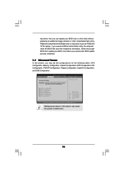
... your system. You may also restart by pressing the reset button on . If you wish to locate and load the Op- You may run the BIOS SETUP UTILITY when you see on your screen. 3.1.1BIOS Menu Bar The top of the screen has a menu bar with its test routines. erating System... screens and descriptions are for reference purpose only, and they may not exactly match what you start up the default system device to enter the BIOS SETUP UTILITY after POST, restart the system by pressing + + , or by turning the system off and then back on the system chassis. 3. The SPI Memory...
... your system. You may also restart by pressing the reset button on . If you wish to locate and load the Op- You may run the BIOS SETUP UTILITY when you see on your screen. 3.1.1BIOS Menu Bar The top of the screen has a menu bar with its test routines. erating System... screens and descriptions are for reference purpose only, and they may not exactly match what you start up the default system device to enter the BIOS SETUP UTILITY after POST, restart the system by pressing + + , or by turning the system off and then back on the system chassis. 3. The SPI Memory...

User Manual
Page 34
... Main Smart Advanced H/W Monitor Boot Security Exit System Overview System Time System Date [17:00:09] [Wed 04/29/2009] BIOS Version : K10N78D P1.0 Processor Type : AMD Phenom (tm) 8650 Triple-Core Processor (64bit) Processor Speed : 2300MHz Microcode Update : 100F23/1000095 L1 Cache Size : 384KB L2 Cache Size : ...] Use this item to specify the system time. 3.1.2Navigation Keys Please check the following table for all the settings To save changes and exit the BIOS SETUP UTILITY To jump to the Exit Screen or exit the current screen 3.2 Main Screen When you enter the...
... Main Smart Advanced H/W Monitor Boot Security Exit System Overview System Time System Date [17:00:09] [Wed 04/29/2009] BIOS Version : K10N78D P1.0 Processor Type : AMD Phenom (tm) 8650 Triple-Core Processor (64bit) Processor Speed : 2300MHz Microcode Update : 100F23/1000095 L1 Cache Size : 384KB L2 Cache Size : ...] Use this item to specify the system time. 3.1.2Navigation Keys Please check the following table for all the settings To save changes and exit the BIOS SETUP UTILITY To jump to the Exit Screen or exit the current screen 3.2 Main Screen When you enter the...

User Manual
Page 35
...Load Performance Setup Default (IDE/SATA) Load Performance Setup AHCI Mode Load Performance Setup RAID Mode Load Power Saving Setup Default BIOS Update Utility ASRock Instant Flash Exit system setup after loading, please resume optimal default settings. Load Performance Setup Default (IDE/SATA) This performance... boot failure occurs after saving the changes. If system boot failure occurs after loading, please resume optimal default settings. ASRock Instant Flash ASRock Instant Flash is a BIOS flash utility embedded in Flash ROM. Just launch this tool and save the changes and exit the...
...Load Performance Setup Default (IDE/SATA) Load Performance Setup AHCI Mode Load Performance Setup RAID Mode Load Power Saving Setup Default BIOS Update Utility ASRock Instant Flash Exit system setup after loading, please resume optimal default settings. Load Performance Setup Default (IDE/SATA) This performance... boot failure occurs after saving the changes. If system boot failure occurs after loading, please resume optimal default settings. ASRock Instant Flash ASRock Instant Flash is a BIOS flash utility embedded in Flash ROM. Just launch this tool and save the changes and exit the...
User Manual
Page 36
... additional floppy diskette or other complicated flash utility. hard drive, then you execute ASRock Instant Flash utility, the utility will show the BIOS files and their respective information. Select the proper BIOS file to update your BIOS, and reboot your BIOS only in below sections may set the configurations for CPU CPU Configuration Memory Configuration...
... additional floppy diskette or other complicated flash utility. hard drive, then you execute ASRock Instant Flash utility, the utility will show the BIOS files and their respective information. Select the proper BIOS file to update your BIOS, and reboot your BIOS only in below sections may set the configurations for CPU CPU Configuration Memory Configuration...
User Manual
Page 37
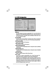
...value is [Auto]. Configuration options: [Disabled] and [Enabled]. Configuration options: [Auto], [Enabled] and [Disabled]. If you will enable ASRock AM2 Boost function, which will improve the memory performance. Please set this function may reduce CPU voltage and memory frequency, and lead to..., Inc. Boot Failure Guard Enable or disable the feature of Boot Failure Guard. The default value is [Auto]. 3.4.1 CPU Configuration BIOS SETUP UTILITY Advanced CPU Configuration Overclock Mode CPU Frequency (MHz) PCIE Frequency (MHz) CPU/LDT Spread Spectrum SATA Spread Spectrum Boot Failure...
...value is [Auto]. Configuration options: [Disabled] and [Enabled]. Configuration options: [Auto], [Enabled] and [Disabled]. If you will enable ASRock AM2 Boost function, which will improve the memory performance. Please set this function may reduce CPU voltage and memory frequency, and lead to..., Inc. Boot Failure Guard Enable or disable the feature of Boot Failure Guard. The default value is [Auto]. 3.4.1 CPU Configuration BIOS SETUP UTILITY Advanced CPU Configuration Overclock Mode CPU Frequency (MHz) PCIE Frequency (MHz) CPU/LDT Spread Spectrum SATA Spread Spectrum Boot Failure...
User Manual
Page 38
... both of Processor Frequency and Processor Voltage. Configuration options: [Enabled] and [Disabled]. North Bridge Maximum Frequency This option appears only when you adopt AM2 CPU. BIOS SETUP UTILITY Advanced CPU Configuration Overclock Mode CPU Frequency (MHz) PCIE Frequency (MHz) CPU/LDT Spread Spectrum SATA Spread Spectrum Boot Failure Guard Cool' n' Quiet...
... both of Processor Frequency and Processor Voltage. Configuration options: [Enabled] and [Disabled]. North Bridge Maximum Frequency This option appears only when you adopt AM2 CPU. BIOS SETUP UTILITY Advanced CPU Configuration Overclock Mode CPU Frequency (MHz) PCIE Frequency (MHz) CPU/LDT Spread Spectrum SATA Spread Spectrum Boot Failure Guard Cool' n' Quiet...

User Manual
Page 40
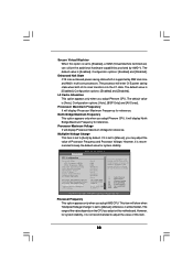
... memory controller mode. It allows you adopt Phenom CPU, there is [Auto]. 40 TRCD Use this option is [XOR of this to [6CLK]. 3.4.2 Memory Configuration BIOS SETUP UTILITY Advanced Memory Configuration Memory Clock Flexibility Option Memory Controller Mode Power Down Enable Bank Interleaving Channel Interleaving Timing : 5-5-5-15 CAS Latency (CL) TRCD...
... memory controller mode. It allows you adopt Phenom CPU, there is [Auto]. 40 TRCD Use this option is [XOR of this to [6CLK]. 3.4.2 Memory Configuration BIOS SETUP UTILITY Advanced Memory Configuration Memory Clock Flexibility Option Memory Controller Mode Power Down Enable Bank Interleaving Channel Interleaving Timing : 5-5-5-15 CAS Latency (CL) TRCD...


