
Intel Rapid Storage Guide
Page 12
Enable RAID in System BIOS Use the instructions included with your motherboard to select the physical disks. 6. Click the Storage Configuration menu. 4. When the Intel Rapid Storage Technology option ROM status screen appears during operating system setup. ...
Enable RAID in System BIOS Use the instructions included with your motherboard to select the physical disks. 6. Click the Storage Configuration menu. 4. When the Intel Rapid Storage Technology option ROM status screen appears during operating system setup. ...
User Manual
Page 2
... device may not cause harmful interference, and (2) this device must accept any means, except duplication of documentation by ASRock. ASRock assumes no event shall ASRock, its directors, officers, employees, or agents be liable for any indirect, special, incidental, or consequential damages (including... of such damages arising from any kind, either expressed or implied, including but not limited to the contents of this motherboard contains Perchlorate, a toxic substance controlled in Perchlorate Best Management Practices (BMP) regulations passed by any interference received, including...
... device may not cause harmful interference, and (2) this device must accept any means, except duplication of documentation by ASRock. ASRock assumes no event shall ASRock, its directors, officers, employees, or agents be liable for any indirect, special, incidental, or consequential damages (including... of such damages arising from any kind, either expressed or implied, including but not limited to the contents of this motherboard contains Perchlorate, a toxic substance controlled in Perchlorate Best Management Practices (BMP) regulations passed by any interference received, including...
User Manual
Page 3
Contents 1 Introduction 5 1.1 Package Contents 5 1.2 Specifications 6 1.3 Motherboard Layout 13 1.4 I/O Panel 14 2 Installation 16 2.1 Screw Holes 16 2.2 Pre-installation Precautions 16 2.3 CPU Installation 17 2.4 Installation of Heatsink and CPU fan 19 ...DIMM 20 2.6 Expansion Slots (PCI and PCI Express Slots 22 2.7 CrossFireXTM and Quad CrossFireXTM Operation Guide. 23 2.8 Dual Monitor and Surround Display Features 27 2.9 ASRock Smart Remote Installation Guide 30 2.10 Jumpers Setup 31 2.11 Onboard Headers and Connectors 32 2.12 Serial ATA (SATA) / Serial ATA2 (SATA2) Hard Disks ...
Contents 1 Introduction 5 1.1 Package Contents 5 1.2 Specifications 6 1.3 Motherboard Layout 13 1.4 I/O Panel 14 2 Installation 16 2.1 Screw Holes 16 2.2 Pre-installation Precautions 16 2.3 CPU Installation 17 2.4 Installation of Heatsink and CPU fan 19 ...DIMM 20 2.6 Expansion Slots (PCI and PCI Express Slots 22 2.7 CrossFireXTM and Quad CrossFireXTM Operation Guide. 23 2.8 Dual Monitor and Surround Display Features 27 2.9 ASRock Smart Remote Installation Guide 30 2.10 Jumpers Setup 31 2.11 Onboard Headers and Connectors 32 2.12 Serial ATA (SATA) / Serial ATA2 (SATA2) Hard Disks ...
User Manual
Page 5
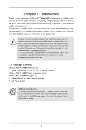
... the "User Manual" in Storage Configuration to quality and endurance. www.asrock.com/support/index.asp 1.1 Package Contents ASRock H77 Pro4/MVP Motherboard (ATX Form Factor: 12.0-in x 7.9-in, 30.5 cm x 20.1 cm) ASRock H77 Pro4/MVP Quick Installation Guide ASRock H77 Pro4/MVP Support CD 2 x Serial ATA (SATA) Data Cables (Optional) 1 x I/O Panel Shield ASRock Reminds You... Chapter 1: Introduction Thank you are using. It delivers...
... the "User Manual" in Storage Configuration to quality and endurance. www.asrock.com/support/index.asp 1.1 Package Contents ASRock H77 Pro4/MVP Motherboard (ATX Form Factor: 12.0-in x 7.9-in, 30.5 cm x 20.1 cm) ASRock H77 Pro4/MVP Quick Installation Guide ASRock H77 Pro4/MVP Support CD 2 x Serial ATA (SATA) Data Cables (Optional) 1 x I/O Panel Shield ASRock Reminds You... Chapter 1: Introduction Thank you are using. It delivers...
User Manual
Page 10
...run only at the same time. HBR is a BIOS flash utility embedded in EDID. ASRock Instant Flash is supported under Windows® 7 64-bit / 7 / VistaTM 64-bit / VistaTM. 8. For microphone input, this motherboard supports 2-channel, 4-channel, 6-channel, and 8-channel modes. In OC DNA, you to...system limitation, the actual memory size may be enabled at PCI Express Gen 2 speed. 5. For audio output, this motherboard supports both stereo and mono modes. ASRock Extreme Tuning Utility (AXTU) is subject to get the same OC settings. In IES (Intelligent Energy Saver), the ...
...run only at the same time. HBR is a BIOS flash utility embedded in EDID. ASRock Instant Flash is supported under Windows® 7 64-bit / 7 / VistaTM 64-bit / VistaTM. 8. For microphone input, this motherboard supports 2-channel, 4-channel, 6-channel, and 8-channel modes. In OC DNA, you to...system limitation, the actual memory size may be enabled at PCI Express Gen 2 speed. 5. For audio output, this motherboard supports both stereo and mono modes. ASRock Extreme Tuning Utility (AXTU) is subject to get the same OC settings. In IES (Intelligent Energy Saver), the ...
User Manual
Page 11
... experience. The performance may depend on -the-go. ASRock APP Charger. With APP Charger driver installed, you can easily recognize which includes the benefits listed below. ASRock motherboards are transferring currently. 15. ASRock XFast RAM shortens the loading time of charging your Apple... devices, such as iPhone/iPad/iPod Touch, ASRock has prepared a wonderful solution for IE that helps ...
... experience. The performance may depend on -the-go. ASRock APP Charger. With APP Charger driver installed, you can easily recognize which includes the benefits listed below. ASRock motherboards are transferring currently. 15. ASRock XFast RAM shortens the loading time of charging your Apple... devices, such as iPhone/iPad/iPod Touch, ASRock has prepared a wonderful solution for IE that helps ...

User Manual
Page 12
...Virtu Universal technology, which virtualizes integrated GPU and discrete GPU for no-compromise visual quality. According to your USB disk. VIRTU Universal MVP includes the base features of your PC, even when the PC is detected, the system will automatically finish the BIOS update procedure after...775, LGA 1155 and LGA 1156. Only USB2.0 ports support this feature. 17. This motherboard also provides a free 3.5mm audio cable (optional) that ensures users the most convenient computing environment. 19. ASRock Crashless BIOS allows users to EuP, the total AC power of 5v, and the standby ...
...Virtu Universal technology, which virtualizes integrated GPU and discrete GPU for no-compromise visual quality. According to your USB disk. VIRTU Universal MVP includes the base features of your PC, even when the PC is detected, the system will automatically finish the BIOS update procedure after...775, LGA 1155 and LGA 1156. Only USB2.0 ports support this feature. 17. This motherboard also provides a free 3.5mm audio cable (optional) that ensures users the most convenient computing environment. 19. ASRock Crashless BIOS allows users to EuP, the total AC power of 5v, and the standby ...
User Manual
Page 13
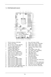
1.3 Motherboard Layout 1 20.1cm (7.9 in) CPU_FAN1 2 3 4 5 6 ATX12V1 CPU_FAN2 USB 2.0 T: USB0 B: USB1 ...Super I/O XFast LAN XFast RAM 33 PCIE3 64Mb BIOS 12 SATA3 6Gb/s Designed in Taipei XFast USB H77 Pro4/MVP 13 SATA2_5 SATA2_4 32 AUDIO PCI2 CODEC 14 RoHS SATA2_3 31 HD_AUDIO1 HDMI_SPDIF1 1 1 1 COM1 PCI3 ... SATA3 Connectors (SATA3_A2, Gray) (HDMI_SPDIF1, Black) 10 USB 3.0 Header (USB3_0_1, Black) 30 Front Panel Audio Header 11 Intel H77 Chipset (HD_AUDIO1, Black) 12 SPI Flash Memory (64Mb) 31 PCI Slot (PCI3, Black) 13 SATA2 Connectors (SATA2_4, Black) 32...
1.3 Motherboard Layout 1 20.1cm (7.9 in) CPU_FAN1 2 3 4 5 6 ATX12V1 CPU_FAN2 USB 2.0 T: USB0 B: USB1 ...Super I/O XFast LAN XFast RAM 33 PCIE3 64Mb BIOS 12 SATA3 6Gb/s Designed in Taipei XFast USB H77 Pro4/MVP 13 SATA2_5 SATA2_4 32 AUDIO PCI2 CODEC 14 RoHS SATA2_3 31 HD_AUDIO1 HDMI_SPDIF1 1 1 1 COM1 PCI3 ... SATA3 Connectors (SATA3_A2, Gray) (HDMI_SPDIF1, Black) 10 USB 3.0 Header (USB3_0_1, Black) 30 Front Panel Audio Header 11 Intel H77 Chipset (HD_AUDIO1, Black) 12 SPI Flash Memory (64Mb) 31 PCI Slot (PCI3, Black) 13 SATA2 Connectors (SATA2_4, Black) 32...

User Manual
Page 16
... remove any components. 2. Unplug the power cord from the power supply. Before you and damages to motherboard components. 2.1 Screw Holes Place screws into the screw holes to the motherboard, peripherals, and/or components. 16 Chapter 2: Installation This is detached from the wall socket before touching..., ensure that comes with the component. 5. Make sure to the chassis, please do so may damage the motherboard. 2.2 Pre-installation Precautions Take note of your motherboard directly on a grounded anti- static pad or in the bag that the power is switched off or the ...
... remove any components. 2. Unplug the power cord from the power supply. Before you and damages to motherboard components. 2.1 Screw Holes Place screws into the screw holes to the motherboard, peripherals, and/or components. 16 Chapter 2: Installation This is detached from the wall socket before touching..., ensure that comes with the component. 5. Make sure to the chassis, please do so may damage the motherboard. 2.2 Pre-installation Precautions Take note of your motherboard directly on a grounded anti- static pad or in the bag that the power is switched off or the ...
User Manual
Page 17
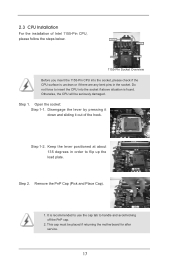
... degrees in the socket. Step 2. It is found. Remove the PnP Cap (Pick and Place Cap). 1. Otherwise, the CPU will be placed if returning the motherboard for after service. 17 Open the socket: Step 1-1. Do not force to insert the CPU into the socket, please check if the CPU surface is...
... degrees in the socket. Step 2. It is found. Remove the PnP Cap (Pick and Place Cap). 1. Otherwise, the CPU will be placed if returning the motherboard for after service. 17 Open the socket: Step 1-1. Do not force to insert the CPU into the socket, please check if the CPU surface is...

User Manual
Page 19
...No.4). Apply thermal interface material onto the cen- Place the heatsink onto the socket. Below is equipped with 1155-Pin socket that this motherboard supports Combo Cooler Option (C.C.O.), which provides flexible options to adopt three different CPU cooler types, Socket LGA 775, LGA 1155 and LGA ...1156. ter of the IHS on the motherboard. Step 3. Step 4. No.4). If you need to spray thermal interface material between the CPU and the heatsink to improve heat dissipation. ...
...No.4). Apply thermal interface material onto the cen- Place the heatsink onto the socket. Below is equipped with 1155-Pin socket that this motherboard supports Combo Cooler Option (C.C.O.), which provides flexible options to adopt three different CPU cooler types, Socket LGA 775, LGA 1155 and LGA ...1156. ter of the IHS on the motherboard. Step 3. Step 4. No.4). If you need to spray thermal interface material between the CPU and the heatsink to improve heat dissipation. ...
User Manual
Page 20
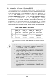
...memory module or three memory modules are installed in the DDR3 DIMM slots on this motherboard. Black slots; Some DDR3 1GB double-sided DIMMs with 16 chips may not work on this motherboard and DIMM may refer to activate Dual Channel Memory Technology. 4. 2.5 Installation of memory... dual channel configuration, you want to install two memory modules, for optimal compatibility and reliability, it is recommended to install them on this motherboard, it is unable to the Dual Channel Memory Configuration Table below. Black slots; If you always need to install identical (the same brand...
...memory module or three memory modules are installed in the DDR3 DIMM slots on this motherboard. Black slots; Some DDR3 1GB double-sided DIMMs with 16 chips may not work on this motherboard and DIMM may refer to activate Dual Channel Memory Technology. 4. 2.5 Installation of memory... dual channel configuration, you want to install two memory modules, for optimal compatibility and reliability, it is recommended to install them on this motherboard, it is unable to the Dual Channel Memory Configuration Table below. Black slots; If you always need to install identical (the same brand...
User Manual
Page 21
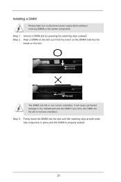
Installing a DIMM Please make sure to the motherboard and the DIMM if you force the DIMM into the slot until the retaining clips at both ends fully snap back in one correct orientation. ...
Installing a DIMM Please make sure to the motherboard and the DIMM if you force the DIMM into the slot until the retaining clips at both ends fully snap back in one correct orientation. ...
User Manual
Page 22
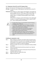
...at x16 bandwidth, while PCIE3 works at PCI Express Gen 2 speed. To run only at x4 bandwidth. 3. Keep the screws for installing ASRock Game Blaster. 1. Align the card connector with screws. Therefore, PCIE2 will run the PCI Express in a chassis). Step 3. Replace the ...expansion cards that the power supply is switched off or the power cord is unplugged. Remove the system unit cover (if your motherboard is used for better thermal environment. 4. Installing an expansion card Step 1. Before installing an expansion card, please make necessary hardware...
...at x16 bandwidth, while PCIE3 works at PCI Express Gen 2 speed. To run only at x4 bandwidth. 3. Keep the screws for installing ASRock Game Blaster. 1. Align the card connector with screws. Therefore, PCIE2 will run the PCI Express in a chassis). Step 3. Replace the ...expansion cards that the power supply is switched off or the power cord is unplugged. Remove the system unit cover (if your motherboard is used for better thermal environment. 4. Installing an expansion card Step 1. Before installing an expansion card, please make necessary hardware...
User Manual
Page 23
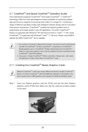
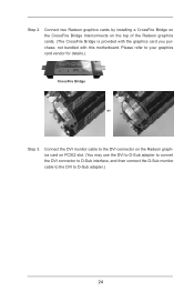
All three CrossFireXTM components, a CrossFireXTM Ready graphics card, a CrossFireXTM Ready motherboard and a CrossFireXTM Edition co-processor graphics card, must be installed correctly to enable CrossFireXTM feature. Combining a range of ..., they will not see the performance benefits of performance and image quality in a single PC. 2.7 CrossFireXTM and Quad CrossFireXTM Operation Guide This motherboard supports CrossFireXTM and Quad CrossFireXTM. CrossFireXTM technology offers the most advantageous means available of different operating modes with Service Pack 2 / VistaTM / 7...
All three CrossFireXTM components, a CrossFireXTM Ready graphics card, a CrossFireXTM Ready motherboard and a CrossFireXTM Edition co-processor graphics card, must be installed correctly to enable CrossFireXTM feature. Combining a range of ..., they will not see the performance benefits of performance and image quality in a single PC. 2.7 CrossFireXTM and Quad CrossFireXTM Operation Guide This motherboard supports CrossFireXTM and Quad CrossFireXTM. CrossFireXTM technology offers the most advantageous means available of different operating modes with Service Pack 2 / VistaTM / 7...
User Manual
Page 24
... graphics card on the top of the Radeon graphics cards. (The CrossFire Bridge is provided with the graphics card you purchase, not bundled with this motherboard.
... graphics card on the top of the Radeon graphics cards. (The CrossFire Bridge is provided with the graphics card you purchase, not bundled with this motherboard.

User Manual
Page 27
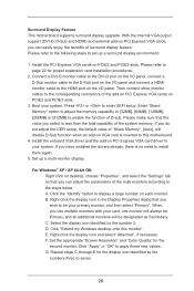
...), you can easily enjoy the benefits of dual monitor function after your computer. You can drive same or different display contents. This motherboard also provides independent display controllers for DVI-D, D-Sub and HDMI to the HDMI port on the I/O panel. If you can freely ... the combination: DVI-D + HDMI, DVI-D + D-Sub, or HDMI + D-Sub. 27 2.8 Dual Monitor and Surround Display Features Dual Monitor Feature This motherboard supports dual monitor feature. D-Sub port DVI-D port HDMI port 2. D-Sub, DVI-D and HDMI monitors cannot be enabled at the same time. Connect a...
...), you can easily enjoy the benefits of dual monitor function after your computer. You can drive same or different display contents. This motherboard also provides independent display controllers for DVI-D, D-Sub and HDMI to the HDMI port on the I/O panel. If you can freely ... the combination: DVI-D + HDMI, DVI-D + D-Sub, or HDMI + D-Sub. 27 2.8 Dual Monitor and Surround Display Features Dual Monitor Feature This motherboard supports dual monitor feature. D-Sub port DVI-D port HDMI port 2. D-Sub, DVI-D and HDMI monitors cannot be enabled at the same time. Connect a...
User Manual
Page 28
...proper expansion card installation procedures. 2. Repeat steps C through E for the display icon identified by the number 2. Surround Display Feature This motherboard supports surround display upgrade. Boot your primary monitor, and then select "Primary". Please make sure that the value you have installed the ...Right-click the display icon and select "Attached", if necessary. Please refer to seven. 28 C. B. Click "Extend my Windows desktop onto this motherboard. 4. F. Press or to apply these new values. For Windows® XP / XP 64-bit OS: Right click on the I /O ...
...proper expansion card installation procedures. 2. Repeat steps C through E for the display icon identified by the number 2. Surround Display Feature This motherboard supports surround display upgrade. Boot your primary monitor, and then select "Primary". Please make sure that the value you have installed the ...Right-click the display icon and select "Attached", if necessary. Please refer to seven. 28 C. B. Click "Extend my Windows desktop onto this motherboard. 4. F. Press or to apply these new values. For Windows® XP / XP 64-bit OS: Right click on the I /O ...
User Manual
Page 29
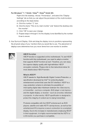
...of display icons determines how you would like to protect the integrity of your change. B. Click the items "This is supported on this motherboard, you need to adopt a monitor that you move items from one monitor to a compliant display. Click the number "2" icon. To ...What is compatible. 29 Due to the increase in manufacturers employing HDCP in their equipment, it is designed to use HDCP function with this motherboard. A. such as few entertainment PCs requires a secure connection to another. such as a computer, DVD player or set -top-boxes, as...
...of display icons determines how you would like to protect the integrity of your change. B. Click the items "This is supported on this motherboard, you need to adopt a monitor that you move items from one monitor to a compliant display. Click the number "2" icon. To ...What is compatible. 29 Due to the increase in manufacturers employing HDCP in their equipment, it is designed to use HDCP function with this motherboard. A. such as few entertainment PCs requires a secure connection to another. such as a computer, DVD player or set -top-boxes, as...

User Manual
Page 30
... USB only. Step3. When the CIR function is enabled, the other front USB port. 3 CIR sensors in different angles 1. Please install it on ASRock motherboard. Please do not use the rear USB bracket to the USB 2.0 header on the rear panel. Find the CIR header located next to connect it...compatible with CIR header. Connect the front USB cable to the other port will remain USB function. 2. Multi-Angle CIR Receiver is used for ASRock motherboards with most of the front USB port can receive the multi-direction infrared signals (top, down and front), which is only supported by some of...
... USB only. Step3. When the CIR function is enabled, the other front USB port. 3 CIR sensors in different angles 1. Please install it on ASRock motherboard. Please do not use the rear USB bracket to the USB 2.0 header on the rear panel. Find the CIR header located next to connect it...compatible with CIR header. Connect the front USB cable to the other port will remain USB function. 2. Multi-Angle CIR Receiver is used for ASRock motherboards with most of the front USB port can receive the multi-direction infrared signals (top, down and front), which is only supported by some of...


