
User Manual
Page 1
All rights reserved. 1 H67M-ITX/HT H67M-ITX User Manual Version 1.0 Published January 2011 Copyright©2011 ASRock INC.
All rights reserved. 1 H67M-ITX/HT H67M-ITX User Manual Version 1.0 Published January 2011 Copyright©2011 ASRock INC.

User Manual
Page 2
... the FCC Rules. "Perchlorate Material-special handling may cause undesired operation. With respect to the implied warranties or conditions of ASRock Inc. CALIFORNIA, USA ONLY The Lithium battery adopted on this manual, ASRock does not provide warranty of any defect or error in this device must accept any interference received, including interference that...
... the FCC Rules. "Perchlorate Material-special handling may cause undesired operation. With respect to the implied warranties or conditions of ASRock Inc. CALIFORNIA, USA ONLY The Lithium battery adopted on this manual, ASRock does not provide warranty of any defect or error in this device must accept any interference received, including interference that...

User Manual
Page 5
... as well. Chapter 3 and 4 contain the configuration guide to the "User Manual" in our support CD for purchasing ASRock H67M-ITX/HT / H67M-ITX motherboard, a reliable motherboard produced under ASRock's consistently stringent quality control. For the BIOS setup, please refer to BIOS setup and information of this motherboard, please visit our website for specifi...
... as well. Chapter 3 and 4 contain the configuration guide to the "User Manual" in our support CD for purchasing ASRock H67M-ITX/HT / H67M-ITX motherboard, a reliable motherboard produced under ASRock's consistently stringent quality control. For the BIOS setup, please refer to BIOS setup and information of this motherboard, please visit our website for specifi...
User Manual
Page 22
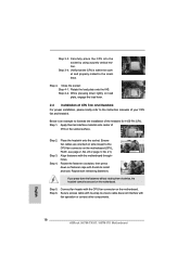
... equipped with remaining fasteners. Step 1. Step 4. Repeat with 1155-Pin socket that the CPU and the heatsink are oriented on side closest to the instruction manuals of your CPU fan and heatsink. Connect fan header with thumb to the CPU_FAN connector (CPU_FAN1, see page 12, No. 23 or page 13, No...
... equipped with remaining fasteners. Step 1. Step 4. Repeat with 1155-Pin socket that the CPU and the heatsink are oriented on side closest to the instruction manuals of your CPU fan and heatsink. Connect fan header with thumb to the CPU_FAN connector (CPU_FAN1, see page 12, No. 23 or page 13, No...

User Manual
Page 31
... J_SENSE OUT2_R MIC2_R MIC2_L This is in S1 sleep state. B. Connect Audio_R (RIN) to OUT2_R and Audio_L (LIN) to the "FrontMic" Tab in our manual and chassis manual to the front panel audio header as below . Connect the power switch, reset switch and system status indicator on the chassis front panel. Please...
... J_SENSE OUT2_R MIC2_R MIC2_L This is in S1 sleep state. B. Connect Audio_R (RIN) to OUT2_R and Audio_L (LIN) to the "FrontMic" Tab in our manual and chassis manual to the front panel audio header as below . Connect the power switch, reset switch and system status indicator on the chassis front panel. Please...

User Manual
Page 36
... connector interfaces, the IDE 1x4-pin conventional power connector interface is installed into system properly. Points of our motherboard is available on our website: www.asrock.com 2. SATA power cable with SATA 15-pin power connector interface A. 2.15 SATA / SATAII / SATA3 HDD Hot Plug Feature and Operation Guide ... or data loss. 36 Make sure your SATA / SATAII / SATA3 HDD can support Hot Plug function from your dealer or HDD user manual. Without SATA 15-pin power connector interface, the SATA / SATAII / SATA3 Hot Plug cannot be damaged under the Hot Plug operation. 3.
... connector interfaces, the IDE 1x4-pin conventional power connector interface is installed into system properly. Points of our motherboard is available on our website: www.asrock.com 2. SATA power cable with SATA 15-pin power connector interface A. 2.15 SATA / SATAII / SATA3 HDD Hot Plug Feature and Operation Guide ... or data loss. 36 Make sure your SATA / SATAII / SATA3 HDD can support Hot Plug function from your dealer or HDD user manual. Without SATA 15-pin power connector interface, the SATA / SATAII / SATA3 Hot Plug cannot be damaged under the Hot Plug operation. 3.

User Manual
Page 44
... item to adjust Turbo Boost power limit. The default is [Auto]. Refresh Cyle Time (tRFC) Use this item to change Command Rate (CR) Auto/Manual setting. The default is [Auto]. The default is [Auto]. 44 CAS# Latency (tCL) Use this item to change CAS# Latency (tCL) Auto... assigns appropriate frequency automatically. Core Current Limit Use this item to change RAS# Active Time (tRAS) Auto/Manual setting. RAS# Active Time (tRAS) Use this item to change Write Recovery Time (tWR) Auto/Manual setting. The default is in Turbo mode. The default is [Auto]. Write to Read Delay (tWTR) ...
... item to adjust Turbo Boost power limit. The default is [Auto]. Refresh Cyle Time (tRFC) Use this item to change Command Rate (CR) Auto/Manual setting. The default is [Auto]. The default is [Auto]. 44 CAS# Latency (tCL) Use this item to change CAS# Latency (tCL) Auto... assigns appropriate frequency automatically. Core Current Limit Use this item to change RAS# Active Time (tRAS) Auto/Manual setting. RAS# Active Time (tRAS) Use this item to change Write Recovery Time (tWR) Auto/Manual setting. The default is in Turbo mode. The default is [Auto]. Write to Read Delay (tWTR) ...

User Manual
Page 45
Four Activate Window (tFAW) Use this item to [1.107V]. Configuration options: [Auto], [0.925V] to change Four Activate Window (tFAW) Auto/Manual setting. Configuration options: [Auto], [Slow] and [Fast]. Configuration options: [Auto], [1.05V] to [1.800V]. The default value is [Auto]. Configuration options: [Auto], [1....
Four Activate Window (tFAW) Use this item to [1.107V]. Configuration options: [Auto], [0.925V] to change Four Activate Window (tFAW) Auto/Manual setting. Configuration options: [Auto], [Slow] and [Fast]. Configuration options: [Auto], [1.05V] to [1.800V]. The default value is [Auto]. Configuration options: [Auto], [1....

Quick Installation Guide
Page 9
... Thank you for specific information about the model you require technical support related to this manual occur, the updated version will be found in the user manual presented in our support CD for details. 9 ASRock H67M-ITX/HT / H67M-ITX Motherboard English Because the motherboard specifications and the BIOS software might be updated, the...
... Thank you for specific information about the model you require technical support related to this manual occur, the updated version will be found in the user manual presented in our support CD for details. 9 ASRock H67M-ITX/HT / H67M-ITX Motherboard English Because the motherboard specifications and the BIOS software might be updated, the...

Quick Installation Guide
Page 13
About the setting of "Hyper Threading Technology", please check page 47 of "User Manual" in EDID. Please check Intel® website for the operation procedures of the four monitors only. You can choose to get the same OC settings. D-... support CD. 2. Please check the table on page 19 for proper connection. 8. Your friends then can save your OC settings as HDMIport. 6. ASRock website: http://www.asrock.com 13 ASRock H67M-ITX/HT / H67M-ITX Motherboard English For audio output, this motherboard supports both stereo and mono modes. In Hardware Monitor, it shows the fan speed and...
About the setting of "Hyper Threading Technology", please check page 47 of "User Manual" in EDID. Please check Intel® website for the operation procedures of the four monitors only. You can choose to get the same OC settings. D-... support CD. 2. Please check the table on page 19 for proper connection. 8. Your friends then can save your OC settings as HDMIport. 6. ASRock website: http://www.asrock.com 13 ASRock H67M-ITX/HT / H67M-ITX Motherboard English For audio output, this motherboard supports both stereo and mono modes. In Hardware Monitor, it shows the fan speed and...
Quick Installation Guide
Page 18
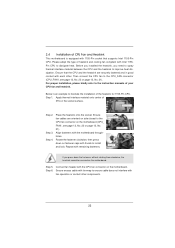
... lightly on the motherboard. Carefully place the CPU into the socket by using a purely vertical motion. Step 4-2. Step 5. English 18 ASRock H67M-ITX/HT / H67M-ITX Motherboard Step 3-3. Step 3-4. Rotate the load plate onto the IHS. While pressing down the fasteners without rotating them clockwise, the heatsink ...and Heatsink For proper installation, please kindly refer to the orient keys. Below is within the socket and properly mated to the instruction manuals of IHS on the motherboard (CPU_ FAN1, see page 2, No. 23 or page 3, No. 21). Apply thermal interface material ...
... lightly on the motherboard. Carefully place the CPU into the socket by using a purely vertical motion. Step 4-2. Step 5. English 18 ASRock H67M-ITX/HT / H67M-ITX Motherboard Step 3-3. Step 3-4. Rotate the load plate onto the IHS. While pressing down the fasteners without rotating them clockwise, the heatsink ...and Heatsink For proper installation, please kindly refer to the orient keys. Below is within the socket and properly mated to the instruction manuals of IHS on the motherboard (CPU_ FAN1, see page 2, No. 23 or page 3, No. 21). Apply thermal interface material ...

Quick Installation Guide
Page 27
...Then click "FrontMic". Adjust "Recording Volume". You may configure the way to OUT2_L. The LED is off (S5). 27 ASRock H67M-ITX/HT / H67M-ITX Motherboard MIC_RET and OUT_RET are for AC'97 audio panel. Select "Recorder". High Definition Audio supports Jack Sensing, but the panel... PANEL1) (see p.2 No. 20 or p.3 No. 18) GND PRESENCE# MIC_RET OUT_RET 1 OUT2_L J_SENSE OUT2_R MIC2_R MIC2_L This is in our manual and chassis manual to connect them for HD audio panel only. Connect Mic_IN (MIC) to the reset switch on the chassis front panel. C. D. Front Panel...
...Then click "FrontMic". Adjust "Recording Volume". You may configure the way to OUT2_L. The LED is off (S5). 27 ASRock H67M-ITX/HT / H67M-ITX Motherboard MIC_RET and OUT_RET are for AC'97 audio panel. Select "Recorder". High Definition Audio supports Jack Sensing, but the panel... PANEL1) (see p.2 No. 20 or p.3 No. 18) GND PRESENCE# MIC_RET OUT_RET 1 OUT2_L J_SENSE OUT2_R MIC2_R MIC2_L This is in our manual and chassis manual to connect them for HD audio panel only. Connect Mic_IN (MIC) to the reset switch on the chassis front panel. C. D. Front Panel...

Quick Installation Guide
Page 32
...utility; If you start up the computer, please press or during the Power-On-Self-Test (POST) to display the menus. 32 ASRock H67M-ITX/HT / H67M-ITX Motherboard English The BIOS Setup program is a menu-driven program, which allows you to scroll through its test routines. For the detailed information... on the system chassis. It will enhance motherboard features. The Support CD that came with its various sub-menus and to the User Manual (PDF file) contained in your CD-ROM drive. otherwise, POST continues with the motherboard contains necessary drivers and useful utilities that...
...utility; If you start up the computer, please press or during the Power-On-Self-Test (POST) to display the menus. 32 ASRock H67M-ITX/HT / H67M-ITX Motherboard English The BIOS Setup program is a menu-driven program, which allows you to scroll through its test routines. For the detailed information... on the system chassis. It will enhance motherboard features. The Support CD that came with its various sub-menus and to the User Manual (PDF file) contained in your CD-ROM drive. otherwise, POST continues with the motherboard contains necessary drivers and useful utilities that...

RAID Installation Guide
Page 2
This section will guide you how to create RAID on this guide carefully. 1. You may install SATA hard disks on SATA ports. 2 Guide to Serial ATA (SATA) Hard Disks Installation of "User Manual" in this motherboard for internal storage devices. Please read the RAID configurations in the support CD. For SATA installation guide, please refer to SATA Hard Disks Installation 1.1 Serial ATA (SATA) Hard Disks Installation Intel H67 chipset supports Serial ATA (SATA) hard disks with RAID functions, including RAID 0, RAID 1, RAID 10, RAID 5, and Intel Rapid Storage.
This section will guide you how to create RAID on this guide carefully. 1. You may install SATA hard disks on SATA ports. 2 Guide to Serial ATA (SATA) Hard Disks Installation of "User Manual" in this motherboard for internal storage devices. Please read the RAID configurations in the support CD. For SATA installation guide, please refer to SATA Hard Disks Installation 1.1 Serial ATA (SATA) Hard Disks Installation Intel H67 chipset supports Serial ATA (SATA) hard disks with RAID functions, including RAID 0, RAID 1, RAID 10, RAID 5, and Intel Rapid Storage.
