
Intel Rapid Storage Guide
Page 12
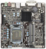
... physical disks. 6. The F6 installation method is not required for Microsoft Windows Vista* or Note Microsoft Windows 7*. Select 1: Create RAID Volume and press Enter. 3. Click the Storage Configuration menu. 4. When the Intel Rapid Storage Technology option ROM status screen appears during operating system setup. Press Enter to enter the BIOS Setup program after the Power-On-Self-Test (POST) memory test begins. 2. Switch the SATA Operation Mode option to enable RAID in System BIOS Use the instructions included with your motherboard to RAID. 5. Enable RAID...
... physical disks. 6. The F6 installation method is not required for Microsoft Windows Vista* or Note Microsoft Windows 7*. Select 1: Create RAID Volume and press Enter. 3. Click the Storage Configuration menu. 4. When the Intel Rapid Storage Technology option ROM status screen appears during operating system setup. Press Enter to enter the BIOS Setup program after the Power-On-Self-Test (POST) memory test begins. 2. Switch the SATA Operation Mode option to enable RAID in System BIOS Use the instructions included with your motherboard to RAID. 5. Enable RAID...
Intel Rapid Storage Guide
Page 13
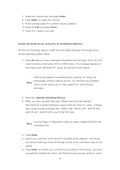
... be visible. 6. Press Enter to Specify Additional Device. 3. Setup will happen immediately after pressing F6. This message appears at the beginning of available SCSI adapters. Nothing will temporarily continue loading drivers. Use the up and down arrow keys to install the Intel Rapid Storage Technology driver during text-mode phase). Press S to confirm your controller and continue. Install the RAID Driver Using the F6 Installation Method Perform the...
... be visible. 6. Press Enter to Specify Additional Device. 3. Setup will happen immediately after pressing F6. This message appears at the beginning of available SCSI adapters. Nothing will temporarily continue loading drivers. Use the up and down arrow keys to install the Intel Rapid Storage Technology driver during text-mode phase). Press S to confirm your controller and continue. Install the RAID Driver Using the F6 Installation Method Perform the...

Intel Rapid Storage Guide
Page 16
... then be used to install the Intel® Rapid Storage Technology driver using F6 when in AHCI/RAID mode In order to install an operating system onto a single Serial ATA hard drive when the system is in the status line that says, Please insert the disk labeled Manufacturer-supplied hardware support disk into Drive A:, insert a floppy disk containing the following steps to load the Intel® Rapid Storage Technology driver during text-mode phase). Setup will...
... then be used to install the Intel® Rapid Storage Technology driver using F6 when in AHCI/RAID mode In order to install an operating system onto a single Serial ATA hard drive when the system is in the status line that says, Please insert the disk labeled Manufacturer-supplied hardware support disk into Drive A:, insert a floppy disk containing the following steps to load the Intel® Rapid Storage Technology driver during text-mode phase). Setup will...

Intel Rapid Storage Guide
Page 18
... using any supported RAID Note controller hub by replacing the text within the quotation marks. // Insert the lines below , as described in the Microsoft document Deployment Guide Automating Windows NT* Setup. Does the system contain a 32-bit or 64-bit processor? o If the system has a 64-bit processor, the files will be located in order to install the RAID or AHCI driver via unattended install. 1. Perform the following command line options...
... using any supported RAID Note controller hub by replacing the text within the quotation marks. // Insert the lines below , as described in the Microsoft document Deployment Guide Automating Windows NT* Setup. Does the system contain a 32-bit or 64-bit processor? o If the system has a 64-bit processor, the files will be located in order to install the RAID or AHCI driver via unattended install. 1. Perform the following command line options...

Intel Smart Response Installation Guide
Page 1
... SSD in Icon tray, lower right-hand corner of the screen. 4. Once open RST GUI from either Start Menu or by step instructions below. You MUST have both the HDD you want to desktop, open , click on the "Enable Acceleration" button on the GUI panel. 5. For all required drivers, including RST storage driver version 10.5 or later. 2. UI setup instruction: 1. Intel Smart Response Technology Installation Guide This motherboard supports Intel Smart Response Technology.
... SSD in Icon tray, lower right-hand corner of the screen. 4. Once open RST GUI from either Start Menu or by step instructions below. You MUST have both the HDD you want to desktop, open , click on the "Enable Acceleration" button on the GUI panel. 5. For all required drivers, including RST storage driver version 10.5 or later. 2. UI setup instruction: 1. Intel Smart Response Technology Installation Guide This motherboard supports Intel Smart Response Technology.
RAID Installation Guide
Page 1
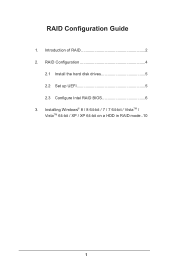
Introduction of RAID 2 2. RAID Configuration 4 2.1 Install the hard disk drives 5 2.2 Set up UEFI 5 2.3 Configure Intel RAID BIOS 6 3. Installing Windows® 8 / 8 64-bit / 7 / 7 64-bit / VistaTM / VistaTM 64-bit / XP / XP 64-bit on a HDD in RAID mode..10 1 RAID Configuration Guide 1.
Introduction of RAID 2 2. RAID Configuration 4 2.1 Install the hard disk drives 5 2.2 Set up UEFI 5 2.3 Configure Intel RAID BIOS 6 3. Installing Windows® 8 / 8 64-bit / 7 / 7 64-bit / VistaTM / VistaTM 64-bit / XP / XP 64-bit on a HDD in RAID mode..10 1 RAID Configuration Guide 1.

RAID Installation Guide
Page 2
... "RAID" stands for the types of RAID This motherboard adopts a chipset that optimizes two identical hard disk drives to a second drive. It will improve data access and storage since the disk array management software will double the data transfer rate of combining two or more hard disk drives into one drive fails. 2 Introduction of RAID your motherboard supports, and notice that copies and maintains an identical image of the same model...
... "RAID" stands for the types of RAID This motherboard adopts a chipset that optimizes two identical hard disk drives to a second drive. It will improve data access and storage since the disk array management software will double the data transfer rate of combining two or more hard disk drives into one drive fails. 2 Introduction of RAID your motherboard supports, and notice that copies and maintains an identical image of the same model...

User Manual
Page 3
... CPU Fan and Heatsink 20 2.3 Installing Memory Modules (DIMM 21 2.4 Expansion Slots (PCI Express Slots 22 2.5 Installing Serial SATA / SATA2 Hard Disks 23 2.6 Power Connectors 24 2.7 Installing the System Panel 25 2.8 Onboard Headers and Connectors 26 2.9 Jumpers Setup 31 2.10 Operating System Setup 32 2.10.1 Installing Windows® 8 / 8 64-bit / 7 / 7 64-bit / VistaTM / VistaTM 64-bit Without RAID 32 2.10.2 Installing Windows® 8 64-bit / 7 64-bit / VistaTM 64-bit on a HDD Larger than 2 terabytes 33 2.11 Installing Drivers 34 2.12 Dual Monitor...
... CPU Fan and Heatsink 20 2.3 Installing Memory Modules (DIMM 21 2.4 Expansion Slots (PCI Express Slots 22 2.5 Installing Serial SATA / SATA2 Hard Disks 23 2.6 Power Connectors 24 2.7 Installing the System Panel 25 2.8 Onboard Headers and Connectors 26 2.9 Jumpers Setup 31 2.10 Operating System Setup 32 2.10.1 Installing Windows® 8 / 8 64-bit / 7 / 7 64-bit / VistaTM / VistaTM 64-bit Without RAID 32 2.10.2 Installing Windows® 8 64-bit / 7 64-bit / VistaTM 64-bit on a HDD Larger than 2 terabytes 33 2.11 Installing Drivers 34 2.12 Dual Monitor...
User Manual
Page 5
... Contents ASRock H61TM-ITX Motherboard (Thin Mini-ITX Form Factor: 6.7-in x 6.7-in, 17.0 cm x 17.0 cm) ASRock H61TM-ITX Quick Installation Guide ASRock H61TM-ITX Support CD 2 x SATA Data Cables (Optional) 1 x SATA 1 to quality and endurance. Chapter 3 includes information about the model you are using. In case any modifications of this manual occur, the updated version will be available on ASRock's website as well. Chapter 2 provides step by step installation instructions. 1. http://www.asrock.com If you for specific...
... Contents ASRock H61TM-ITX Motherboard (Thin Mini-ITX Form Factor: 6.7-in x 6.7-in, 17.0 cm x 17.0 cm) ASRock H61TM-ITX Quick Installation Guide ASRock H61TM-ITX Support CD 2 x SATA Data Cables (Optional) 1 x SATA 1 to quality and endurance. Chapter 3 includes information about the model you are using. In case any modifications of this manual occur, the updated version will be available on ASRock's website as well. Chapter 2 provides step by step installation instructions. 1. http://www.asrock.com If you for specific...

User Manual
Page 34
... Main Menu does not appear automatically, locate and double click on the file "ASRSETUP.EXE" in your CD-ROM drive. Therefore, the drivers you may contact your system will be auto-detected and listed on a specific item then follow the order from top to bottom to install those required drivers. Click on the support CD driver page. 2.11 Installing Drivers The Support CD that comes with the motherboard...
... Main Menu does not appear automatically, locate and double click on the file "ASRSETUP.EXE" in your CD-ROM drive. Therefore, the drivers you may contact your system will be auto-detected and listed on a specific item then follow the order from top to bottom to install those required drivers. Click on the support CD driver page. 2.11 Installing Drivers The Support CD that comes with the motherboard...

User Manual
Page 35
... monitors cannot all be enabled at the same time. You can drive the same or different display contents. DVI-I port HDMI port LVDS port If you have already installed the VGA driver from our support CD and restart your system, you can enjoy dual monitor after your system reboots. 2.12 Dual Monitor Dual Monitor This motherboard supports dual monitor. To enable dual monitor, please connect monitor cables to the respective ports on VGA cards to this motherboard. This motherboard also provides independent display controllers for HDMI...
... monitors cannot all be enabled at the same time. You can drive the same or different display contents. DVI-I port HDMI port LVDS port If you have already installed the VGA driver from our support CD and restart your system, you can enjoy dual monitor after your system reboots. 2.12 Dual Monitor Dual Monitor This motherboard supports dual monitor. To enable dual monitor, please connect monitor cables to the respective ports on VGA cards to this motherboard. This motherboard also provides independent display controllers for HDMI...

User Manual
Page 40
... (POST) to configure your screen. 3.1.1 UEFI Menu Bar The top of the screen has a menu bar with its test routines. Because the UEFI software is constantly being updated, the following selections: Main For setting system time/date information OC Tweaker For overclocking configurations Advanced For advanced system configurations Tool Useful tools H/W Monitor Displays current hardware status Boot For configuring boot settings and boot priority Security For security settings Exit Exit the current screen or the UEFI Setup Utility...
... (POST) to configure your screen. 3.1.1 UEFI Menu Bar The top of the screen has a menu bar with its test routines. Because the UEFI software is constantly being updated, the following selections: Main For setting system time/date information OC Tweaker For overclocking configurations Advanced For advanced system configurations Tool Useful tools H/W Monitor Displays current hardware status Boot For configuring boot settings and boot priority Security For security settings Exit Exit the current screen or the UEFI Setup Utility...

User Manual
Page 48
.... The default value is supported through the native processor instructions HLT and MWAIT and requires no hardware support from the chipset. C1 state is [All]. CPU C6 State Support Use this to enable or disable CPU C3 report to OS. Active Processor Cores Use this technology such as Microsoft® Windows® XP / VistaTM / 7 / 8 is [Auto]. 48 Package C State Support Configure options that includes optimization for this to enable in each processor package...
.... The default value is supported through the native processor instructions HLT and MWAIT and requires no hardware support from the chipset. C1 state is [All]. CPU C6 State Support Use this to enable or disable CPU C3 report to OS. Active Processor Cores Use this technology such as Microsoft® Windows® XP / VistaTM / 7 / 8 is [Auto]. 48 Package C State Support Configure options that includes optimization for this to enable in each processor package...
User Manual
Page 50
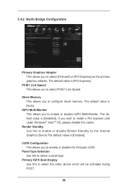
... POST. 50 If you to select PCIE1 Link Speed. Primary IGFX Boot Display Use this to select a panel type. The default value is [Auto]. PCIE1 Link Speed This allows you wish to install a PCI Express card under Windows® VistaTM OS, please disable this to enable or disable Render Standby by the Internal Graphics Device.The default value is [PCI Express]. Share Memory This allows you to select [Onboard] or [PCI Express] as the primary graphics adapter. 3.4.2 North Bridge Configuration...
... POST. 50 If you to select PCIE1 Link Speed. Primary IGFX Boot Display Use this to select a panel type. The default value is [Auto]. PCIE1 Link Speed This allows you wish to install a PCI Express card under Windows® VistaTM OS, please disable this to enable or disable Render Standby by the Internal Graphics Device.The default value is [PCI Express]. Share Memory This allows you to select [Onboard] or [PCI Express] as the primary graphics adapter. 3.4.2 North Bridge Configuration...

User Manual
Page 60
... [Disabled] to enter the OS. [UEFI Setup Only] - If you have USB compatibility issues, it is [Enabled]. Enables support for details of these four options: [Enabled] - USB devices are allowed to be used only under legacy OS and UEFI setup when [Disabled] is [Enabled]. The default value is selected. Enables legacy support if USB devices are four configuration options: [Enabled], [Auto], [Disabled] and [UEFI Setup Only]. There are connected. [Disabled] - Please refer to the descriptions below for legacy USB. [Auto] - USB 3.0 Controller Use this if your USB devices encounter...
... [Disabled] to enter the OS. [UEFI Setup Only] - If you have USB compatibility issues, it is [Enabled]. Enables support for details of these four options: [Enabled] - USB devices are allowed to be used only under legacy OS and UEFI setup when [Disabled] is [Enabled]. The default value is selected. Enables legacy support if USB devices are four configuration options: [Enabled], [Auto], [Disabled] and [UEFI Setup Only]. There are connected. [Disabled] - Please refer to the descriptions below for legacy USB. [Auto] - USB 3.0 Controller Use this if your USB devices encounter...

User Manual
Page 65
... configure the boot settings and the boot priority. Bootup Num-Lock If this to boot from a USB storage device. [Ultra Fast]: There are using the keyboard. 3.7 Boot Screen This section displays the available devices on your computer's boot time. Boot From Onboard LAN Use this is not allowed to enable or disable Boot From Onboard LAN. You will not be able to [On], it is set to enter BIOS Setup by using an external graphics card, the VBIOS must support UEFI GOP in windows. 3. Disable...
... configure the boot settings and the boot priority. Bootup Num-Lock If this to boot from a USB storage device. [Ultra Fast]: There are using the keyboard. 3.7 Boot Screen This section displays the available devices on your computer's boot time. Boot From Onboard LAN Use this is not allowed to enable or disable Boot From Onboard LAN. You will not be able to [On], it is set to enter BIOS Setup by using an external graphics card, the VBIOS must support UEFI GOP in windows. 3. Disable...
Quick Installation Guide
Page 5
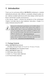
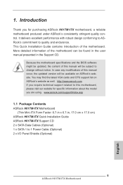
... for specific information about the model you for purchasing ASRock H61TM-ITX motherboard, a reliable motherboard produced under ASRock's consistently stringent quality control. You may find the latest VGA cards and CPU support list on ASRock's website. www.asrock.com/support/index.asp 1.1 Package Contents ASRock H61TM-ITX Motherboard (Thin Mini-ITX Form Factor: 6.7-in x 6.7-in the Support CD. Introduction Thank you are using. This Quick Installation Guide contains introduction of this manual occur, the updated version will be updated, the...
... for specific information about the model you for purchasing ASRock H61TM-ITX motherboard, a reliable motherboard produced under ASRock's consistently stringent quality control. You may find the latest VGA cards and CPU support list on ASRock's website. www.asrock.com/support/index.asp 1.1 Package Contents ASRock H61TM-ITX Motherboard (Thin Mini-ITX Form Factor: 6.7-in x 6.7-in the Support CD. Introduction Thank you are using. This Quick Installation Guide contains introduction of this manual occur, the updated version will be updated, the...
Quick Installation Guide
Page 6
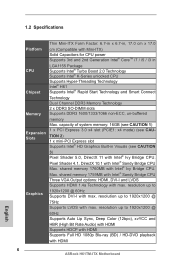
...-DVD playback with HDMI 6 ASRock H61TM-ITX Motherboard English resolution up to 1920x1200 @ 75Hz Supports LVDS with max. 1.2 Specifications Platform CPU Chipset Memory Expansion Slots Graphics Thin Mini-ITX Form Factor: 6.7-in x 6.7-in, 17.0 cm x 17.0 cm (Compatible with Mini-ITX) Solid Capacitors for CPU power Supports 3rd and 2nd Generation Intel® CoreTM i7 / i5 / i3 in Visuals (see CAU- capacity of system memory: 16GB (see CAUTION 1) 1 x PCI Express 3.0 x4 slot (PCIE1: x4 mode...
...-DVD playback with HDMI 6 ASRock H61TM-ITX Motherboard English resolution up to 1920x1200 @ 75Hz Supports LVDS with max. 1.2 Specifications Platform CPU Chipset Memory Expansion Slots Graphics Thin Mini-ITX Form Factor: 6.7-in x 6.7-in, 17.0 cm x 17.0 cm (Compatible with Mini-ITX) Solid Capacitors for CPU power Supports 3rd and 2nd Generation Intel® CoreTM i7 / i5 / i3 in Visuals (see CAU- capacity of system memory: 16GB (see CAUTION 1) 1 x PCI Express 3.0 x4 slot (PCIE1: x4 mode...
Quick Installation Guide
Page 14
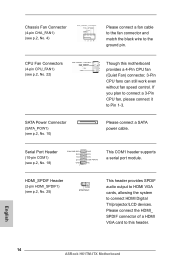
... connect a fan cable to the fan connector and match the black wire to this motherboard provides a 4-Pin CPU fan (Quiet Fan) connector, 3-Pin CPU fans can still work even without fan speed control. Chassis Fan Connector (4-pin CHA_FAN1) (see p.2, No. 18) COM PWR/DCD RXD TXD DTR GND 1 DSR RTS CTS COM PWR/RI NC This COM1 header supports a serial port module. English 14 ASRock H61TM-ITX Motherboard CPU Fan Connectors (4-pin CPU_FAN1) (see p.2, No. 22) SATA Power Connector (SATA_POW1) (see p.2, No. 25) This header provides SPDIF audio output to HDMI VGA cards, allowing...
... connect a fan cable to the fan connector and match the black wire to this motherboard provides a 4-Pin CPU fan (Quiet Fan) connector, 3-Pin CPU fans can still work even without fan speed control. Chassis Fan Connector (4-pin CHA_FAN1) (see p.2, No. 18) COM PWR/DCD RXD TXD DTR GND 1 DSR RTS CTS COM PWR/RI NC This COM1 header supports a serial port module. English 14 ASRock H61TM-ITX Motherboard CPU Fan Connectors (4-pin CPU_FAN1) (see p.2, No. 22) SATA Power Connector (SATA_POW1) (see p.2, No. 25) This header provides SPDIF audio output to HDMI VGA cards, allowing...
Quick Installation Guide
Page 17
...otherwise, POST continues with the motherboard contains necessary drivers and useful utilities that will display the Main Menu automatically if "AUTORUN" is designed to enter the BIOS Setup utility; The BIOS Setup program is enabled in the Support CD. 3. For detailed information about BIOS Setup, please refer to display the menu. 17 ASRock H61TM-ITX Motherboard English BIOS Information The Flash Memory on the system chassis. Software Support CD information This motherboard supports various Microsoft® Windows® operating systems: 8 / 8 64-bit / 7 / 7 64-bit / VistaTM...
...otherwise, POST continues with the motherboard contains necessary drivers and useful utilities that will display the Main Menu automatically if "AUTORUN" is designed to enter the BIOS Setup utility; The BIOS Setup program is enabled in the Support CD. 3. For detailed information about BIOS Setup, please refer to display the menu. 17 ASRock H61TM-ITX Motherboard English BIOS Information The Flash Memory on the system chassis. Software Support CD information This motherboard supports various Microsoft® Windows® operating systems: 8 / 8 64-bit / 7 / 7 64-bit / VistaTM...


