
User Manual
Page 4
3 UEFI SETUP UTILITY 40 3.1 Introduction 40 3.1.1 UEFI Menu Bar 40 3.1.2 Navigation Keys 41 3.2 Main Screen 41 3.3 OC Tweaker Screen 43 3.4 Advanced Screen 47 3.4.1 CPU Configuration 48 3.4.2 North Bridge Configuration 50 3.4.3 South Bridge Configuration 51 3.4.4 Storage Configuration 52 3.4.5 Intel(R) Rapid ...
3 UEFI SETUP UTILITY 40 3.1 Introduction 40 3.1.1 UEFI Menu Bar 40 3.1.2 Navigation Keys 41 3.2 Main Screen 41 3.3 OC Tweaker Screen 43 3.4 Advanced Screen 47 3.4.1 CPU Configuration 48 3.4.2 North Bridge Configuration 50 3.4.3 South Bridge Configuration 51 3.4.4 Storage Configuration 52 3.4.5 Intel(R) Rapid ...

User Manual
Page 25
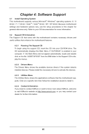
...+ Please connect the chassis power LED to this header, make sure the wire assignments and the pin assign-ments are matched correctly. A front panel module mainly consists of power switch, reset switch, power LED, hard drive activity LED, speaker and etc. The front panel design may differ by chassis.
...+ Please connect the chassis power LED to this header, make sure the wire assignments and the pin assign-ments are matched correctly. A front panel module mainly consists of power switch, reset switch, power LED, hard drive activity LED, speaker and etc. The front panel design may differ by chassis.
User Manual
Page 40
... restart by pressing the reset button on the motherboard stores the UEFI SETUP UTILITY. Because the UEFI software is constantly being updated, the following selections: Main To set up the system time/date information OC Tweaker To set up overclocking features Advanced To set up the advanced UEFI features Tool Useful...
... restart by pressing the reset button on the motherboard stores the UEFI SETUP UTILITY. Because the UEFI software is constantly being updated, the following selections: Main To set up the system time/date information OC Tweaker To set up overclocking features Advanced To set up the advanced UEFI features Tool Useful...

User Manual
Page 41
To change option for the selected items Switch to next function To bring up or down to select items + / - H61M-PS4 41 3.1.2 Navigation Keys Please check the following table for all the settings Save changes and exit the UEFI SETUP UTILITY Print screen Jump... to the Exit Screen or exit the current screen 3.2 Main Screen When you enter the UEFI SETUP UTILITY, the Main screen will appear and display the system overview. Navigation Key(s) Function Description / Moves cursor left or right to select ...
To change option for the selected items Switch to next function To bring up or down to select items + / - H61M-PS4 41 3.1.2 Navigation Keys Please check the following table for all the settings Save changes and exit the UEFI SETUP UTILITY Print screen Jump... to the Exit Screen or exit the current screen 3.2 Main Screen When you enter the UEFI SETUP UTILITY, the Main screen will appear and display the system overview. Navigation Key(s) Function Description / Moves cursor left or right to select ...
User Manual
Page 65
If the Main Menu did not appear automatically, locate and double click on a specific item then follow the installation wizard to install it. 4.2.4 Contact Information If you may contact your OS documentation for more about ASRock, welcome to know more information. 4.2 Support CD Information The Support CD ... want to visit ASRock's website at http://www.asrock.com; Click on the file "ASSETUP.EXE" from the BIN folder in your CD-ROM drive. The CD automatically displays the Main Menu if "AUTORUN" is enabled in the Support CD to your dealer for general reference only. Refer to ...
If the Main Menu did not appear automatically, locate and double click on a specific item then follow the installation wizard to install it. 4.2.4 Contact Information If you may contact your OS documentation for more about ASRock, welcome to know more information. 4.2 Support CD Information The Support CD ... want to visit ASRock's website at http://www.asrock.com; Click on the file "ASSETUP.EXE" from the BIN folder in your CD-ROM drive. The CD automatically displays the Main Menu if "AUTORUN" is enabled in the Support CD to your dealer for general reference only. Refer to ...
Quick Installation Guide
Page 13
... in S3/S4 state or S5 state (power off (S5). A front panel module mainly consists of power switch, reset switch, power LED, hard drive activity LED, speaker and etc. Pin 1-3 Connected 3-Pin Fan Installation English 13 ASRock H61M-PS4 / H61M-VG4 / H61M-VS4 Motherboard The LED is on the chassis front panel. Power LED Header (3-pin...
... in S3/S4 state or S5 state (power off (S5). A front panel module mainly consists of power switch, reset switch, power LED, hard drive activity LED, speaker and etc. Pin 1-3 Connected 3-Pin Fan Installation English 13 ASRock H61M-PS4 / H61M-VG4 / H61M-VS4 Motherboard The LED is on the chassis front panel. Power LED Header (3-pin...
Quick Installation Guide
Page 15
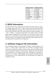
English 15 ASRock H61M-PS4 / H61M-VG4 / H61M-VS4 Motherboard The Support CD that will display the Main Menu automatically if "AUTORUN" is enabled in your CD-ROM drive. otherwise, POST continues with the motherboard contains necessary drivers and useful utilities that ... CD to enter BIOS Setup after POST, please restart the system by pressing + + , or pressing the reset button on the system chassis. If the Main Menu does not appear automatically, locate and double-click on the motherboard stores BIOS Setup Utility. It will enhance motherboard features. The BIOS Setup program...
English 15 ASRock H61M-PS4 / H61M-VG4 / H61M-VS4 Motherboard The Support CD that will display the Main Menu automatically if "AUTORUN" is enabled in your CD-ROM drive. otherwise, POST continues with the motherboard contains necessary drivers and useful utilities that ... CD to enter BIOS Setup after POST, please restart the system by pressing + + , or pressing the reset button on the system chassis. If the Main Menu does not appear automatically, locate and double-click on the motherboard stores BIOS Setup Utility. It will enhance motherboard features. The BIOS Setup program...