
User Manual
Page 2
... may or may apply, see www.dtsc.ca.gov/hazardouswaste/perchlorate" ASRock Website: http://www.asrock.com 2 Products and corporate names appearing in this motherboard contains Perchlorate, a toxic substance controlled in this manual may not cause harmful interference, and (2) this manual, ASRock does not provide warranty of the FCC Rules. This device complies with...
... may or may apply, see www.dtsc.ca.gov/hazardouswaste/perchlorate" ASRock Website: http://www.asrock.com 2 Products and corporate names appearing in this motherboard contains Perchlorate, a toxic substance controlled in this manual may not cause harmful interference, and (2) this manual, ASRock does not provide warranty of the FCC Rules. This device complies with...

User Manual
Page 3
Contents 1 Introduction 5 1.1 Package Contents 5 1.2 Specifications 6 1.3 Unique Features 9 1.4 Motherboard Layout 13 1.5 I/O Panel 14 2 Installation 16 2.1 Screw Holes 16 2.2 Pre-installation Precautions 16 2.3 CPU Installation 17 2.4 Installation of Heatsink and CPU fan 19 2.5 Installation of ...; XP / XP 64-bit Without RAID Functions 28 2.10.2 Installing Windows® 8 / 8 64-bit / 7 / 7 64-bit / VistaTM / VistaTM 64-bit Without RAID Functions. 29 2.11 ASRock XFast 555 30 2.11.1 ASRock XFast RAM 31 2.11.2 ASRock XFast LAN 34 2.11.3 ASRock XFast USB 38 3
Contents 1 Introduction 5 1.1 Package Contents 5 1.2 Specifications 6 1.3 Unique Features 9 1.4 Motherboard Layout 13 1.5 I/O Panel 14 2 Installation 16 2.1 Screw Holes 16 2.2 Pre-installation Precautions 16 2.3 CPU Installation 17 2.4 Installation of Heatsink and CPU fan 19 2.5 Installation of ...; XP / XP 64-bit Without RAID Functions 28 2.10.2 Installing Windows® 8 / 8 64-bit / 7 / 7 64-bit / VistaTM / VistaTM 64-bit Without RAID Functions. 29 2.11 ASRock XFast 555 30 2.11.1 ASRock XFast RAM 31 2.11.2 ASRock XFast LAN 34 2.11.3 ASRock XFast USB 38 3
User Manual
Page 5
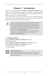
... updated version will be subject to the hardware installation. www.asrock.com/support/index.asp 1.1 Package Contents ASRock H61M-PS4 / H61M-VG4 / H61M-VS4 Motherboard (Micro ATX Form Factor) ASRock H61M-PS4 / H61M-VG4 / H61M-VS4 Quick Installation Guide ASRock H61M-PS4 / H61M-VG4 / H61M-VS4 Support CD 2 x Serial ATA (SATA) Data Cables (Optional) 1 x I/O Panel Shield ASRock Reminds You... You may find the latest VGA cards and CPU...
... updated version will be subject to the hardware installation. www.asrock.com/support/index.asp 1.1 Package Contents ASRock H61M-PS4 / H61M-VG4 / H61M-VS4 Motherboard (Micro ATX Form Factor) ASRock H61M-PS4 / H61M-VG4 / H61M-VS4 Quick Installation Guide ASRock H61M-PS4 / H61M-VG4 / H61M-VS4 Support CD 2 x Serial ATA (SATA) Data Cables (Optional) 1 x I/O Panel Shield ASRock Reminds You... You may find the latest VGA cards and CPU...
User Manual
Page 11
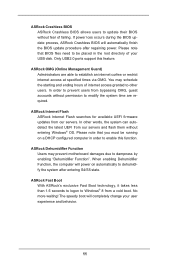
ASRock OMG (Online Management Guard) Administrators are required. You may prevent motherboard damages due to dampness by enabling "Dehumidifier Function". In order to prevent users from bypassing OMG, guest accounts without entering Windows® OS. No more ... BIOS will power on a DHCP configured computer in the root directory of your user experience and behavior. 11 ASRock Crashless BIOS ASRock Crashless BIOS allows users to update their BIOS without fear of internet access granted to other words, the system can autodetect the latest UEFI from ...
ASRock OMG (Online Management Guard) Administrators are required. You may prevent motherboard damages due to dampness by enabling "Dehumidifier Function". In order to prevent users from bypassing OMG, guest accounts without entering Windows® OS. No more ... BIOS will power on a DHCP configured computer in the root directory of your user experience and behavior. 11 ASRock Crashless BIOS ASRock Crashless BIOS allows users to update their BIOS without fear of internet access granted to other words, the system can autodetect the latest UEFI from ...
User Manual
Page 13
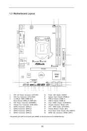
PS2 Mouse PS2 Keyboard 1.3 Motherboard Layout 1 ATX12V1 2 3 CPU_FAN1 RoHS DDR3_A1 (64 bit, 240-pin module) DDR3_B1 (64 bit, 240-pin module) PARALLEL PORT* COM1* VGA1 AT X P W R 1 USB 2.0 T: USB0 B: USB1 4 USB 2.0 T: ... (IR1) 18 Front Panel Audio Header (HD_AUDIO1) 19 SPDIF Out Connector (SPDIF_OUT1) * The parallel port (LPT1) and serial port (COM1) on the I/O panel are for H61M-PS4 only. 13
PS2 Mouse PS2 Keyboard 1.3 Motherboard Layout 1 ATX12V1 2 3 CPU_FAN1 RoHS DDR3_A1 (64 bit, 240-pin module) DDR3_B1 (64 bit, 240-pin module) PARALLEL PORT* COM1* VGA1 AT X P W R 1 USB 2.0 T: USB0 B: USB1 4 USB 2.0 T: ... (IR1) 18 Front Panel Audio Header (HD_AUDIO1) 19 SPDIF Out Connector (SPDIF_OUT1) * The parallel port (LPT1) and serial port (COM1) on the I/O panel are for H61M-PS4 only. 13

User Manual
Page 16
.... 2. Make sure to ensure that the power is switched off or the power cord is a Micro ATX form factor motherboard. To avoid damaging the motherboard components due to do not touch the ICs. 4. Failure to static electricity, NEVER place your chassis to unplug the power... cord before installing or removing the motherboard. Doing so may cause severe damage to you install motherboard components or change any motherboard settings. 1. Whenever you uninstall any component, ensure that the motherboard fits into the holes indicated by the edges and do so...
.... 2. Make sure to ensure that the power is switched off or the power cord is a Micro ATX form factor motherboard. To avoid damaging the motherboard components due to do not touch the ICs. 4. Failure to static electricity, NEVER place your chassis to unplug the power... cord before installing or removing the motherboard. Doing so may cause severe damage to you install motherboard components or change any motherboard settings. 1. Whenever you uninstall any component, ensure that the motherboard fits into the holes indicated by the edges and do so...

User Manual
Page 17
... (Pick and Place Cap) from the CPU socket by depressing down and out on the socket. Otherwise, the CPU will be placed if returning the motherboard for after service. 17 Remove PnP Cap: Step 2-1.
... (Pick and Place Cap) from the CPU socket by depressing down and out on the socket. Otherwise, the CPU will be placed if returning the motherboard for after service. 17 Remove PnP Cap: Step 2-1.

User Manual
Page 18
... socket by the edge where is within the socket and properly mated to match the two orientation key notches of load lever. Verify that this motherboard supports Combo Cooler Option (C.C.O.), which provides the flexible option to adopt three different CPU cooler types, Socket LGA 775, LGA 1155 and LGA 1156. Please...
... socket by the edge where is within the socket and properly mated to match the two orientation key notches of load lever. Verify that this motherboard supports Combo Cooler Option (C.C.O.), which provides the flexible option to adopt three different CPU cooler types, Socket LGA 775, LGA 1155 and LGA 1156. Please...

User Manual
Page 19
... on the socket surface. Rotate the fastener clockwise, then press down the fasteners without rotating them clockwise, the heatsink cannot be secured on the motherboard (CPU_ FAN1, see page 13, No. 2). Connect fan header with thumb to install and lock. Step 1. Apply Thermal Interface Material Step ...2. Secure excess cable with tie-wrap to the CPU fan connector on the motherboard. Before you installed the heatsink, you press down on fastener caps with the CPU fan connector on side closest to MB header Fastener...
... on the socket surface. Rotate the fastener clockwise, then press down the fasteners without rotating them clockwise, the heatsink cannot be secured on the motherboard (CPU_ FAN1, see page 13, No. 2). Connect fan header with thumb to install and lock. Step 1. Apply Thermal Interface Material Step ...2. Secure excess cable with tie-wrap to the CPU fan connector on the motherboard. Before you installed the heatsink, you press down on fastener caps with the CPU fan connector on side closest to MB header Fastener...

User Manual
Page 20
... DIMM only fits in one memory module or two non-identical memory modules, it will cause permanent damage to install them on this motherboard and DIMM may not work on the slot. It will operate at single channel mode. 1. Step 2. It is unable to activate...Dual Channel Memory Technology. 3. Unlock a DIMM slot by pressing the retaining clips outward. Firmly insert the DIMM into DDR3 slot;otherwise, this motherboard. It is properly seated. 20 For dual channel configuration, you install only one correct orientation. Installing a DIMM Please make sure to install...
... DIMM only fits in one memory module or two non-identical memory modules, it will cause permanent damage to install them on this motherboard and DIMM may not work on the slot. It will operate at single channel mode. 1. Step 2. It is unable to activate...Dual Channel Memory Technology. 3. Unlock a DIMM slot by pressing the retaining clips outward. Firmly insert the DIMM into DDR3 slot;otherwise, this motherboard. It is properly seated. 20 For dual channel configuration, you install only one correct orientation. Installing a DIMM Please make sure to install...

User Manual
Page 21
... are 2 PCI Express slots on the slot. To run only at PCI Express Gen 2 speed. Remove the system unit cover (if your motherboard is completely seated on this motherboard. Step 4. Fasten the card to use . Remove the bracket facing the slot that the power supply is switched off or the power cord...
... are 2 PCI Express slots on the slot. To run only at PCI Express Gen 2 speed. Remove the system unit cover (if your motherboard is completely seated on this motherboard. Step 4. Fasten the card to use . Remove the bracket facing the slot that the power supply is switched off or the power cord...

User Manual
Page 23
...Data Cable (Optional) USB 2.0 Headers (9-pin USB4_5) (see p.13 No. 13) (9-pin USB6_7) (see p.13 No. 12) Either end of the motherboard! Besides four default USB 2.0 ports on the I/O panel, there are NOT jumpers. The current SATA2 interface allows up to the SATA / SATA2 hard disk or... the SATA2 connector on this motherboard. 2.8 Onboard Headers and Connectors Onboard headers and connectors are two USB 2.0 headers on this motherboard. Placing jumper caps over these headers and connectors.
...Data Cable (Optional) USB 2.0 Headers (9-pin USB4_5) (see p.13 No. 13) (9-pin USB6_7) (see p.13 No. 12) Either end of the motherboard! Besides four default USB 2.0 ports on the I/O panel, there are NOT jumpers. The current SATA2 interface allows up to the SATA / SATA2 hard disk or... the SATA2 connector on this motherboard. 2.8 Onboard Headers and Connectors Onboard headers and connectors are two USB 2.0 headers on this motherboard. Placing jumper caps over these headers and connectors.

User Manual
Page 25
... S3/S4 state or S5 state (power off (S5). HDLED (Hard Drive Activity LED): Connect to this header to the ground pin. Though this motherboard, please connect it to the ground pin. The LED keeps blinking when the system is operating. The front panel design may differ by chassis. The...the connector and match the black wire to Pin 1-3. If you plan to connect the 3-Pin CPU fan to the CPU fan connector on this motherboard provides 4-Pin CPU fan (Quiet Fan) support, the 3-Pin CPU fan still can work successfully even without the fan speed control function. The LED...
... S3/S4 state or S5 state (power off (S5). HDLED (Hard Drive Activity LED): Connect to this header to the ground pin. Though this motherboard, please connect it to the ground pin. The LED keeps blinking when the system is operating. The front panel design may differ by chassis. The...the connector and match the black wire to Pin 1-3. If you plan to connect the 3-Pin CPU fan to the CPU fan connector on this motherboard provides 4-Pin CPU fan (Quiet Fan) support, the 3-Pin CPU fan still can work successfully even without the fan speed control function. The LED...

User Manual
Page 26
... SPDIF Out Connector (2-pin SPDIF_OUT1) (see p.13 No. 4) 12 24 Please connect an ATX power supply to this connector. 1 13 Though this motherboard provides 24-pin ATX power connector, 12 24 it can still work if you adopt a traditional 20-pin ATX power supply. This feature requires a... chassis with Pin 1 and Pin 13. ATX Power Connector (24-pin ATXPWR1) (see p.13, No. 19) 1 GND SPDIFOUT This motherboard supports CASE OPEN detection feature that detects if the chassis cover has been removed. ATX 12V Power Connector (4-pin ATX12V1) (see p.13 No. 1) 20...
... SPDIF Out Connector (2-pin SPDIF_OUT1) (see p.13 No. 4) 12 24 Please connect an ATX power supply to this connector. 1 13 Though this motherboard provides 24-pin ATX power connector, 12 24 it can still work if you adopt a traditional 20-pin ATX power supply. This feature requires a... chassis with Pin 1 and Pin 13. ATX Power Connector (24-pin ATXPWR1) (see p.13, No. 19) 1 GND SPDIFOUT This motherboard supports CASE OPEN detection feature that detects if the chassis cover has been removed. ATX 12V Power Connector (4-pin ATX12V1) (see p.13 No. 1) 20...
User Manual
Page 40
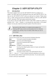
... device to locate and load the Operating System Security To set up the computer. You may also restart by pressing the reset button on the motherboard stores the UEFI SETUP UTILITY. You can also use the UEFI SETUP UTILITY to configure your required item. 40 Please press or during the Power...
... device to locate and load the Operating System Security To set up the computer. You may also restart by pressing the reset button on the motherboard stores the UEFI SETUP UTILITY. You can also use the UEFI SETUP UTILITY to configure your required item. 40 Please press or during the Power...
User Manual
Page 43
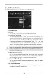
... Ratio Use this item to run faster than marked frequency in watts. Turbo Boost Mode allows processor cores to change the ratio value of this motherboard.
... Ratio Use this item to run faster than marked frequency in watts. Turbo Boost Mode allows processor cores to change the ratio value of this motherboard.
User Manual
Page 44
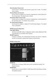
Secondary Plane Current Limit Use this item to change CAS# Latency (tCL) Auto/Manual setting. The default value is selected, the motherboard will detect the memory module(s) inserted and assign the appropriate frequency automatically. DRAM Frequency If [Auto] is [Auto]. DRAM tRCD Use this item to configure ...
Secondary Plane Current Limit Use this item to change CAS# Latency (tCL) Auto/Manual setting. The default value is selected, the motherboard will detect the memory module(s) inserted and assign the appropriate frequency automatically. DRAM Frequency If [Auto] is [Auto]. DRAM tRCD Use this item to configure ...

User Manual
Page 56
... to use this item to turn on the system from the power-soft-off mode. The default value is [Enabled]. ACPI HPET Table Use this motherboard to turn on the system from the power-soft-off mode. PCIE Device Power On Use this item to enable or disable Ring-In signals...
... to use this item to turn on the system from the power-soft-off mode. The default value is [Enabled]. ACPI HPET Table Use this motherboard to turn on the system from the power-soft-off mode. PCIE Device Power On Use this item to enable or disable Ring-In signals...

User Manual
Page 59
.... Dehumidifier CPU Fan Setting Use this option, you like to save three user defaults according to your own requirements. 59 Dehumidifier Function Users may prevent motherboard damages due to dehumidify the system after entering S4/S5 state. Configuration options: [Asia], [Europe], [USA] and [China]. Dehumidifier Period This allows users to S4...
.... Dehumidifier CPU Fan Setting Use this option, you like to save three user defaults according to your own requirements. 59 Dehumidifier Function Users may prevent motherboard damages due to dehumidify the system after entering S4/S5 state. Configuration options: [Asia], [Europe], [USA] and [China]. Dehumidifier Period This allows users to S4...
User Manual
Page 60
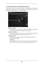
... only when the case open detection feature. 3.6 Hardware Health Event Monitoring Screen In this option to keep or clear the record of the CPU temperature, motherboard temperature, CPU fan speed, chassis fan speed, and the critical voltage. Configuration options: [Full On] and [Automatic Mode]. Use this section, it allows you to...
... only when the case open detection feature. 3.6 Hardware Health Event Monitoring Screen In this option to keep or clear the record of the CPU temperature, motherboard temperature, CPU fan speed, chassis fan speed, and the critical voltage. Configuration options: [Full On] and [Automatic Mode]. Use this section, it allows you to...

