
User Manual
Page 2
...be registered trademarks or copyrights of their respective companies, and are furnished for informational use only and subject to infringe. ASRock assumes no event shall ASRock, its directors, officers, employees, or agents be liable for any indirect, special, incidental, or consequential...the purchaser for backup purpose, without written consent of the FCC Rules. Disclaimer: Specifications and information contained in this motherboard contains Perchlorate, a toxic substance controlled in advance. When you discard the Lithium battery in California, USA, please follow the ...
...be registered trademarks or copyrights of their respective companies, and are furnished for informational use only and subject to infringe. ASRock assumes no event shall ASRock, its directors, officers, employees, or agents be liable for any indirect, special, incidental, or consequential...the purchaser for backup purpose, without written consent of the FCC Rules. Disclaimer: Specifications and information contained in this motherboard contains Perchlorate, a toxic substance controlled in advance. When you discard the Lithium battery in California, USA, please follow the ...

User Manual
Page 3
Contents 1 Introduction...5 1.1 1.2 1.3 1.4 1.5 2.1 2.2 2.3 2.4 2.5 2.6 Package Contents ...Specifications...Motherboard Layout (H61M-HVGS / H61M-HVS) ...I/O Panel (H61M-HVGS) ...I/O Panel (H61M-HVS) ...Screw Holes...Pre-installation Precautions ...CPU Installation ...Installation of Heatsink and CPU fan ...Installation of Memory Modules (DIMM) ...Expansion Slots (PCI Express Slots)...5 6 12 ...
Contents 1 Introduction...5 1.1 1.2 1.3 1.4 1.5 2.1 2.2 2.3 2.4 2.5 2.6 Package Contents ...Specifications...Motherboard Layout (H61M-HVGS / H61M-HVS) ...I/O Panel (H61M-HVGS) ...I/O Panel (H61M-HVS) ...Screw Holes...Pre-installation Precautions ...CPU Installation ...Installation of Heatsink and CPU fan ...Installation of Memory Modules (DIMM) ...Expansion Slots (PCI Express Slots)...5 6 12 ...

User Manual
Page 5
... well. You may find the latest VGA cards and CPU support lists on ASRock website without notice. www.asrock.com/support/index.asp 1.1 Package Contents ASRock H61M-HVGS / H61M-HVS Motherboard (Micro ATX Form Factor: 8.9-in x 6.8-in, 22.6 cm x 17.3 cm) ASRock H61M-HVGS / H61M-HVS Quick Installation Guide ASRock H61M-HVGS / H61M-HVS Support CD 2 x Serial ATA (SATA) Data Cables (Optional) 1 x I/O Panel Shield...
... well. You may find the latest VGA cards and CPU support lists on ASRock website without notice. www.asrock.com/support/index.asp 1.1 Package Contents ASRock H61M-HVGS / H61M-HVS Motherboard (Micro ATX Form Factor: 8.9-in x 6.8-in, 22.6 cm x 17.3 cm) ASRock H61M-HVGS / H61M-HVS Quick Installation Guide ASRock H61M-HVGS / H61M-HVS Support CD 2 x Serial ATA (SATA) Data Cables (Optional) 1 x I/O Panel Shield...

User Manual
Page 9
...drive, floppy disk or hard drive, then you to access ASRock Instant Flash. In Hardware Monitor, it shows the fan speed and temperature for proper installation. ASRock website: http://www.asrock.com ASRock Instant Flash is no such limitation. Just launch this utility, you to... Please check Intel® website for the operation procedures of ASRock Extreme Tuning Utility (AXTU). ASRock Extreme Tuning Utility (AXTU) is an all-in Flash ROM. About the setting of your friends. This motherboard supports Dual Channel Memory Technology. The maximum shared memory size is...
...drive, floppy disk or hard drive, then you to access ASRock Instant Flash. In Hardware Monitor, it shows the fan speed and temperature for proper installation. ASRock website: http://www.asrock.com ASRock Instant Flash is no such limitation. Just launch this utility, you to... Please check Intel® website for the operation procedures of ASRock Extreme Tuning Utility (AXTU). ASRock Extreme Tuning Utility (AXTU) is an all-in Flash ROM. About the setting of your friends. This motherboard supports Dual Channel Memory Technology. The maximum shared memory size is...

User Manual
Page 10
... friends and your computer and up to RAM (S3), hibernation mode (S4) or power off (S5). The performance may depend on the motherboard functions properly and unplug the power cord, then plug it makes your iPhone charged much quickly from your real-time newsfeed into Standby mode (S1...), Suspend to 40% faster than ever. Before you - ASRock motherboards are exclusively equipped with the SmartView utility that not all the 775 and 1156 CPU Fan can boost USB storage device performance. If you desire...
... friends and your computer and up to RAM (S3), hibernation mode (S4) or power off (S5). The performance may depend on the motherboard functions properly and unplug the power cord, then plug it makes your iPhone charged much quickly from your real-time newsfeed into Standby mode (S1...), Suspend to 40% faster than ever. Before you - ASRock motherboards are exclusively equipped with the SmartView utility that not all the 775 and 1156 CPU Fan can boost USB storage device performance. If you desire...

User Manual
Page 11
... higher than 50% under 1.00W in off mode condition. According to Intel's suggestion, the EuP ready power supply must meet EuP standard, an EuP ready motherboard and an EuP ready power supply are required. According to define the power consumption for more details. 11 For EuP ready power supply...
... higher than 50% under 1.00W in off mode condition. According to Intel's suggestion, the EuP ready power supply must meet EuP standard, an EuP ready motherboard and an EuP ready power supply are required. According to define the power consumption for more details. 11 For EuP ready power supply...

User Manual
Page 12
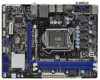
1.3 Motherboard Layout (H61M-HVGS / H61M-HVS) 1 2 3 17.3cm (6.8 in) DX10.1 HDMI 1.4a CPU_FAN1 ErP/EuP Ready ATX12V1 RoHS Designed in Taipei DDR3_B1 (64 bit, 240-pin module) DDR3 USB 2.0 T: USB0 B: ...
1.3 Motherboard Layout (H61M-HVGS / H61M-HVS) 1 2 3 17.3cm (6.8 in) DX10.1 HDMI 1.4a CPU_FAN1 ErP/EuP Ready ATX12V1 RoHS Designed in Taipei DDR3_B1 (64 bit, 240-pin module) DDR3 USB 2.0 T: USB0 B: ...

User Manual
Page 15
...;ts into the holes indicated by the edges and do so may cause severe damage to you uninstall any motherboard settings. 1. To avoid damaging the motherboard components due to static electricity, NEVER place your chassis to use a grounded wrist strap or touch a safety grounded object before touching any component..., ensure that the power is switched off or the power cord is a Micro ATX form factor (8.9" x 6.8", 22.6 x 17.3 cm) motherboard. Also remember to ensure that comes with the component. Failure to the chassis. Hold components by circles to secure the...
...;ts into the holes indicated by the edges and do so may cause severe damage to you uninstall any motherboard settings. 1. To avoid damaging the motherboard components due to static electricity, NEVER place your chassis to use a grounded wrist strap or touch a safety grounded object before touching any component..., ensure that the power is switched off or the power cord is a Micro ATX form factor (8.9" x 6.8", 22.6 x 17.3 cm) motherboard. Also remember to ensure that comes with the component. Failure to the chassis. Hold components by circles to secure the...

User Manual
Page 16
Rotate the load plate to fully open position at approximately 100 degrees. Otherwise, the CPU will be placed if returning the motherboard for after service. 16 Rotate the load lever to insert the CPU into the socket, please check if the CPU surface is unclean or if ...
Rotate the load plate to fully open position at approximately 100 degrees. Otherwise, the CPU will be placed if returning the motherboard for after service. 16 Rotate the load lever to insert the CPU into the socket, please check if the CPU surface is unclean or if ...

User Manual
Page 18
...to dissipate heat. Rotate the fastener clockwise, then press down the fasteners without rotating them clockwise, the heatsink cannot be noticed that this motherboard supports Combo Cooler Option (C.C.O.), which provides the flexible option to adopt three different CPU cooler types, Socket LGA 775, LGA ... page 12, No. 3). Below is equipped with fan operation or contact other . Step 3. 2.4 Installation of CPU Fan and Heatsink This motherboard is an example to illustrate the installation of the heatsink for Socket LGA 1155/1156 CPU fan. 18 Please adopt the type of your CPU...
...to dissipate heat. Rotate the fastener clockwise, then press down the fasteners without rotating them clockwise, the heatsink cannot be noticed that this motherboard supports Combo Cooler Option (C.C.O.), which provides the flexible option to adopt three different CPU cooler types, Socket LGA 775, LGA ... page 12, No. 3). Below is equipped with fan operation or contact other . Step 3. 2.4 Installation of CPU Fan and Heatsink This motherboard is an example to illustrate the installation of the heatsink for Socket LGA 1155/1156 CPU fan. 18 Please adopt the type of your CPU...

User Manual
Page 19
... Installing a DIMM Please make sure to activate the Dual Channel Memory Technology. Step 1. Otherwise, it will cause permanent damage to the motherboard and the DIMM if you always need to install two identical (the same brand, speed, size and chiptype) memory modules in one ...memory module into the slot at incorrect orientation. Step 3. For dual channel configuration, you force the DIMM into DDR3 slot;otherwise, this motherboard. Step 2. It is unable to disconnect power supply before adding or removing DIMMs or the system components. It is properly seated. 19...
... Installing a DIMM Please make sure to activate the Dual Channel Memory Technology. Step 1. Otherwise, it will cause permanent damage to the motherboard and the DIMM if you always need to install two identical (the same brand, speed, size and chiptype) memory modules in one ...memory module into the slot at incorrect orientation. Step 3. For dual channel configuration, you force the DIMM into DDR3 slot;otherwise, this motherboard. Step 2. It is unable to disconnect power supply before adding or removing DIMMs or the system components. It is properly seated. 19...

User Manual
Page 20
... use . Installing an expansion card Step 1. Fasten the card to use . Step 5. PCIE2 (PCIE x1 slot; Remove the system unit cover (if your motherboard is completely seated on this motherboard. Step 6. 20 Keep the screws for PCI Express x16 lane width graphics cards. Step 2. 2.6 Expansion Slots (PCI Express Slots) There are 2 PCI...
... use . Installing an expansion card Step 1. Fasten the card to use . Step 5. PCIE2 (PCIE x1 slot; Remove the system unit cover (if your motherboard is completely seated on this motherboard. Step 6. 20 Keep the screws for PCI Express x16 lane width graphics cards. Step 2. 2.6 Expansion Slots (PCI Express Slots) There are 2 PCI...

User Manual
Page 21
.... To enable dual monitor feature, please follow the below steps: 1. If you have installed onboard VGA driver from our support CD to this motherboard. If you haven't installed onboard VGA driver yet, please install onboard VGA driver from our support CD to support dual VGA output so that ...VGA/D-Sub port on VGA card to your system and restart your system boots. 2.7 Dual Monitor and Surround Display Features Dual Monitor Feature This motherboard supports dual monitor feature. VGA/D-Sub port VGA/HDMI port 2. With the internal VGA output support (HDMI and D-Sub), you can drive ...
.... To enable dual monitor feature, please follow the below steps: 1. If you have installed onboard VGA driver from our support CD to this motherboard. If you haven't installed onboard VGA driver yet, please install onboard VGA driver from our support CD to support dual VGA output so that ...VGA/D-Sub port on VGA card to your system and restart your system boots. 2.7 Dual Monitor and Surround Display Features Dual Monitor Feature This motherboard supports dual monitor feature. VGA/D-Sub port VGA/HDMI port 2. With the internal VGA output support (HDMI and D-Sub), you can drive ...

User Manual
Page 22
...add-on the I/O panel. A. When you use multiple monitors with your primary monitor, and then select "Primary". Click "Extend my Windows desktop onto this motherboard. 4. Connect HDMI monitor cable to VGA/HDMI port on each monitor. Press or to display a large number on the I/O panel, and connect D-Sub monitor... "Attached", if necessary. Please make sure that the value you can adjust the parameters of the system memory. C. G. Surround Display Feature This motherboard supports surround display upgrade. Please refer to the following steps to apply these new values.
...add-on the I/O panel. A. When you use multiple monitors with your primary monitor, and then select "Primary". Click "Extend my Windows desktop onto this motherboard. 4. Connect HDMI monitor cable to VGA/HDMI port on each monitor. Press or to display a large number on the I/O panel, and connect D-Sub monitor... "Attached", if necessary. Please make sure that the value you can adjust the parameters of the system memory. C. G. Surround Display Feature This motherboard supports surround display upgrade. Please refer to the following steps to apply these new values.

User Manual
Page 23
... is my main monitor" and "Extend the desktop onto this monitor". such as few entertainment PCs requires a secure connection to use HDCP function with this motherboard. Products compatible with the HDCP scheme such as DVD players, satellite and cable HDTV set -top box and the digital display, or receiver - Click the... -top-boxes, as well as a monitor, television or projector. Due to the increase in manufacturers employing HDCP in their equipment, it is supported on this motherboard, you move items from one monitor to save your monitors that you would like to a compliant display.
... is my main monitor" and "Extend the desktop onto this monitor". such as few entertainment PCs requires a secure connection to use HDCP function with this motherboard. Products compatible with the HDCP scheme such as DVD players, satellite and cable HDTV set -top box and the digital display, or receiver - Click the... -top-boxes, as well as a monitor, television or projector. Due to the increase in manufacturers employing HDCP in their equipment, it is supported on this motherboard, you move items from one monitor to save your monitors that you would like to a compliant display.

User Manual
Page 25
... six default USB 2.0 ports on the I/O panel, there are NOT jumpers. 2.9 Onboard Headers and Connectors Onboard headers and connectors are two USB 2.0 headers on this motherboard. Serial ATA (SATA) Data Cable (Optional) USB 2.0 Headers (9-pin USB6_7) (see p.12 No. 18) 1 AFD# ERROR# PINIT# SLIN# GND SPD7 SPD6 ACK# SPD5 ...convenient connection of printer devices. 25 The current SATAII interface allows up to the SATA / SATAII hard disk or the SATAII connector on this motherboard. Either end of the motherboard! Each USB 2.0 header can be connected to 3.0 Gb/s data transfer rate.
... six default USB 2.0 ports on the I/O panel, there are NOT jumpers. 2.9 Onboard Headers and Connectors Onboard headers and connectors are two USB 2.0 headers on this motherboard. Serial ATA (SATA) Data Cable (Optional) USB 2.0 Headers (9-pin USB6_7) (see p.12 No. 18) 1 AFD# ERROR# PINIT# SLIN# GND SPD7 SPD6 ACK# SPD5 ...convenient connection of printer devices. 25 The current SATAII interface allows up to the SATA / SATAII hard disk or the SATAII connector on this motherboard. Either end of the motherboard! Each USB 2.0 header can be connected to 3.0 Gb/s data transfer rate.

User Manual
Page 27
... to this header. Chassis Speaker Header (4-pin SPEAKER 1) (see p.12 No. 4) 12 24 Please connect an ATX power supply to this connector. 1 13 Though this motherboard provides 24-pin ATX power connector, it can work if you plan to connect the 3-Pin CPU fan to the CPU fan connector on this... motherboard, please connect it to this motherboard provides 4-Pin CPU fan (Quiet Fan) support, the 3-Pin CPU fan still can still work successfully even without the fan speed control...
... to this header. Chassis Speaker Header (4-pin SPEAKER 1) (see p.12 No. 4) 12 24 Please connect an ATX power supply to this connector. 1 13 Though this motherboard provides 24-pin ATX power connector, it can work if you plan to connect the 3-Pin CPU fan to the CPU fan connector on this... motherboard, please connect it to this motherboard provides 4-Pin CPU fan (Quiet Fan) support, the 3-Pin CPU fan still can still work successfully even without the fan speed control...

User Manual
Page 29
...other end of the SATA data cable to insert and remove the SATA / SATAII HDDs while the system is still power-on this motherboard for SATA host controllers developed thru a joint industry effort. Intel® H61 chipset provides hardware support for Advanced Host controller Interface (...hard disk. 2.11 Hot Plug Function for SATA / SATAII HDDs This motherboard supports Hot Plug function for the action to the motherboard's SATAII connector. 2.10 Serial ATA (SATA) / Serial ATAII (SATAII) Hard Disks Installation This motherboard adopts Intel® H61 chipset that it is called "Hot Plug"...
...other end of the SATA data cable to insert and remove the SATA / SATAII HDDs while the system is still power-on this motherboard for SATA host controllers developed thru a joint industry effort. Intel® H61 chipset provides hardware support for Advanced Host controller Interface (...hard disk. 2.11 Hot Plug Function for SATA / SATAII HDDs This motherboard supports Hot Plug function for the action to the motherboard's SATAII connector. 2.10 Serial ATA (SATA) / Serial ATAII (SATAII) Hard Disks Installation This motherboard adopts Intel® H61 chipset that it is called "Hot Plug"...

User Manual
Page 30
...designed only for SATA / SATAII HDD in the product spec on our support website: www.asrock.com 4. 2.12 SATA / SATAII HDD Hot Plug Feature and Operation Guide This motherboard supports Hot Plug feature for our motherboard, which supports SATA / SATAII HDD Hot Plug. * The SATA / SATAII Hot Plug... our website: www.asrock.com 2. Please read below instructions step by the chipset because of its limitation, the SATA / SATAII Hot Plug support information of attention, before you process the SATA / SATAII HDD Hot Plug, please check below cable accessories from the motherboard gift box pack....
...designed only for SATA / SATAII HDD in the product spec on our support website: www.asrock.com 4. 2.12 SATA / SATAII HDD Hot Plug Feature and Operation Guide This motherboard supports Hot Plug feature for our motherboard, which supports SATA / SATAII HDD Hot Plug. * The SATA / SATAII Hot Plug... our website: www.asrock.com 2. Please read below instructions step by the chipset because of its limitation, the SATA / SATAII Hot Plug support information of attention, before you process the SATA / SATAII HDD Hot Plug, please check below cable accessories from the motherboard gift box pack....

User Manual
Page 31
... SATA / SATAII HDD side. 31 SATA power cable 1x4-pin power connector (White) Step 3 Connect SATA 15-pin power cable connector (Black) end to the motherboard's SATAII connector. Step 1 Please connect SATA power cable 1x4-pin end Step 2 (White) to the SATA / SATAII HDD. Step 2 Unplug SATA 15-pin power cable...
... SATA / SATAII HDD side. 31 SATA power cable 1x4-pin power connector (White) Step 3 Connect SATA 15-pin power cable connector (Black) end to the motherboard's SATAII connector. Step 1 Please connect SATA power cable 1x4-pin end Step 2 (White) to the SATA / SATAII HDD. Step 2 Unplug SATA 15-pin power cable...

