
User Manual
Page 10
...spray thermal grease between the CPU and the heatsink when you can easily enjoy the marvelous charging experience than before. 8. If you - ASRock APP Charger. ASRock XFast USB can be used. 10 To improve heat dissipation, remember to adopt three different CPU cooler types, Socket LGA 775, LGA... 1155 and LGA 1156. Please be noticed that helps you keep in touch with friends on the motherboard functions properly and unplug the ...
...spray thermal grease between the CPU and the heatsink when you can easily enjoy the marvelous charging experience than before. 8. If you - ASRock APP Charger. ASRock XFast USB can be used. 10 To improve heat dissipation, remember to adopt three different CPU cooler types, Socket LGA 775, LGA... 1155 and LGA 1156. Please be noticed that helps you keep in touch with friends on the motherboard functions properly and unplug the ...

User Manual
Page 12
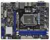
1.3 Motherboard Layout (H61M-HVGS / H61M-HVS) 1 2 3 17.3cm (6.8 in) DX10.1 HDMI 1.4a CPU_FAN1 ErP/EuP Ready ATX12V1 RoHS Designed in Taipei DDR3_B1 (64 bit, 240-pin module) DDR3 USB 2.0 T: USB0 B: ... SATA2_1 CHA_FAN1 COM1 1 USB6_7 PLED PWRBTN 8 1 LPT1 1 1 1 HDLED RESET PANEL1 SATA2_2 SATA2_0 19 18 17 16 15 14 13 12 11 10 9 1 2 3 4 5 6 7 8 9 10 11 12 1155-Pin CPU Socket ATX 12V Power Connector (ATX12V1) CPU Fan Connector (CPU_FAN1) ATX Power Connector (ATXPWR1) 2 x 240-pin DDR3 DIMM Slots (Dual Channel: DDR3_A1, DDR3_B1...
1.3 Motherboard Layout (H61M-HVGS / H61M-HVS) 1 2 3 17.3cm (6.8 in) DX10.1 HDMI 1.4a CPU_FAN1 ErP/EuP Ready ATX12V1 RoHS Designed in Taipei DDR3_B1 (64 bit, 240-pin module) DDR3 USB 2.0 T: USB0 B: ... SATA2_1 CHA_FAN1 COM1 1 USB6_7 PLED PWRBTN 8 1 LPT1 1 1 1 HDLED RESET PANEL1 SATA2_2 SATA2_0 19 18 17 16 15 14 13 12 11 10 9 1 2 3 4 5 6 7 8 9 10 11 12 1155-Pin CPU Socket ATX 12V Power Connector (ATX12V1) CPU Fan Connector (CPU_FAN1) ATX Power Connector (ATXPWR1) 2 x 240-pin DDR3 DIMM Slots (Dual Channel: DDR3_A1, DDR3_B1...

User Manual
Page 16
Load Plate Load Lever Contact Array Socket Body 1155-Pin Socket Overview Before you insert the 1155-Pin CPU into the socket if above situation is recommended to use the cap tab to fully open position at approximately 135 degrees. Open the ... load lever to handle and avoid kicking off the PnP cap. 2. Remove PnP Cap (Pick and Place Cap). 1. 2.3 CPU Installation For the installation of Intel 1155-Pin CPU, please follow the steps below. Step 2. Step 1-3. Step 1. Disengaging the lever by depressing down and out on the socket. Do not force to...
Load Plate Load Lever Contact Array Socket Body 1155-Pin Socket Overview Before you insert the 1155-Pin CPU into the socket if above situation is recommended to use the cap tab to fully open position at approximately 135 degrees. Open the ... load lever to handle and avoid kicking off the PnP cap. 2. Remove PnP Cap (Pick and Place Cap). 1. 2.3 CPU Installation For the installation of Intel 1155-Pin CPU, please follow the steps below. Step 2. Step 1-3. Step 1. Disengaging the lever by depressing down and out on the socket. Do not force to...

User Manual
Page 17
... onto the IHS. Locate Pin1 and the two orientation key notches. Step 4-2. orientation key notch Pin1 alignment key Pin1 alignment key orientation key notch 1155-Pin CPU 1155-Pin Socket For proper inserting, please ensure to the orient keys. Verify that the CPU is marked with the two alignment keys of the... properly mated to match the two orientation key notches of the socket. Orient the CPU with IHS (Integrated Heat Sink) up. Step 3-3. Step 3. Insert the 1155-Pin CPU: Step 3-1.
... onto the IHS. Locate Pin1 and the two orientation key notches. Step 4-2. orientation key notch Pin1 alignment key Pin1 alignment key orientation key notch 1155-Pin CPU 1155-Pin Socket For proper inserting, please ensure to the orient keys. Verify that the CPU is marked with the two alignment keys of the... properly mated to match the two orientation key notches of the socket. Orient the CPU with IHS (Integrated Heat Sink) up. Step 3-3. Step 3. Insert the 1155-Pin CPU: Step 3-1.

User Manual
Page 18
... clockwise, then press down the fasteners without rotating them clockwise, the heatsink cannot be noticed that the CPU and the heatsink are for 1155-Pin CPU. Repeat with the CPU fan connector on the motherboard. Place the heatsink onto the socket. Step 6. Ensure that this motherboard... Please be secured on the motherboard. Align fasteners with Intel 1155Pin CPU to adopt three different CPU cooler types, Socket LGA 775, LGA 1155 and LGA 1156. 2.4 Installation of CPU Fan and Heatsink This motherboard is an example to MB header Fastener slots pointing straight out Press ...
... clockwise, then press down the fasteners without rotating them clockwise, the heatsink cannot be noticed that the CPU and the heatsink are for 1155-Pin CPU. Repeat with the CPU fan connector on the motherboard. Place the heatsink onto the socket. Step 6. Ensure that this motherboard... Please be secured on the motherboard. Align fasteners with Intel 1155Pin CPU to adopt three different CPU cooler types, Socket LGA 775, LGA 1155 and LGA 1156. 2.4 Installation of CPU Fan and Heatsink This motherboard is an example to MB header Fastener slots pointing straight out Press ...

Quick Installation Guide
Page 2
Motherboard Layout (H61M-HVGS / H61M-HVS) PS2 Mouse PS2 Keyboard 1 17.3cm (6.8 in) 23 HDMI 1.4a CPU_FAN1 ATX12V1 RoHS VGA1 AT X P W R 1 22... SATA2_1 SPEAKER1 1 CHA_FAN1 8 COM1 USB6_7 PLED PWRBTN 1 1 1 HDLED RESET PANEL1 SATA2_2 SATA2_0 19 18 17 16 15 14 13 12 11 10 9 1 1155-Pin CPU Socket 2 ATX 12V Power Connector (ATX12V1) 3 CPU Fan Connector (CPU_FAN1) 4 ATX Power Connector (ATXPWR1) 5 2 x 240-pin DDR3 DIMM Slots... 21 Clear CMOS Jumper (CLRCMOS1) 22 PCI Express 2.0 x16 Slot (PCIE1, Blue) 23 Power Fan Connector (PWR_FAN1) 2 ASRock H61M-HVGS / H61M-HVS Motherboard English
Motherboard Layout (H61M-HVGS / H61M-HVS) PS2 Mouse PS2 Keyboard 1 17.3cm (6.8 in) 23 HDMI 1.4a CPU_FAN1 ATX12V1 RoHS VGA1 AT X P W R 1 22... SATA2_1 SPEAKER1 1 CHA_FAN1 8 COM1 USB6_7 PLED PWRBTN 1 1 1 HDLED RESET PANEL1 SATA2_2 SATA2_0 19 18 17 16 15 14 13 12 11 10 9 1 1155-Pin CPU Socket 2 ATX 12V Power Connector (ATX12V1) 3 CPU Fan Connector (CPU_FAN1) 4 ATX Power Connector (ATXPWR1) 5 2 x 240-pin DDR3 DIMM Slots... 21 Clear CMOS Jumper (CLRCMOS1) 22 PCI Express 2.0 x16 Slot (PCIE1, Blue) 23 Power Fan Connector (PWR_FAN1) 2 ASRock H61M-HVGS / H61M-HVS Motherboard English

Quick Installation Guide
Page 10
... history, your Facebook friends and your computer and up to 40% faster than ever. ASRock APP Charger. Please be used. 10 ASRock H61M-HVGS / H61M-HVS Motherboard English If you can easily enjoy the marvelous charging experience than before. With... APP Charger driver installed, you desire a faster, less restricted way of the device. 11. To improve heat dissipation, remember to adopt three different CPU cooler types, Socket LGA 775, LGA 1155 and LGA 1156. ASRock...
... history, your Facebook friends and your computer and up to 40% faster than ever. ASRock APP Charger. Please be used. 10 ASRock H61M-HVGS / H61M-HVS Motherboard English If you can easily enjoy the marvelous charging experience than before. With... APP Charger driver installed, you desire a faster, less restricted way of the device. 11. To improve heat dissipation, remember to adopt three different CPU cooler types, Socket LGA 775, LGA 1155 and LGA 1156. ASRock...

Quick Installation Guide
Page 12
...avoid damaging the motherboard components due to secure the moth- Hold components by the edges and do not over-tighten the screws! English 12 ASRock H61M-HVGS / H61M-HVS Motherboard Do not force to insert the CPU into the screw holes to static electricity, NEVER place your motherboard directly on a grounded... antstatic pad or in the bag that comes with the component. 5. Whenever you insert the 1155-Pin CPU into the socket, please check if the CPU surface is unclean or if there is found. Load Plate Contact Array Load Lever...
...avoid damaging the motherboard components due to secure the moth- Hold components by the edges and do not over-tighten the screws! English 12 ASRock H61M-HVGS / H61M-HVS Motherboard Do not force to insert the CPU into the screw holes to static electricity, NEVER place your motherboard directly on a grounded... antstatic pad or in the bag that comes with the component. 5. Whenever you insert the 1155-Pin CPU into the socket, please check if the CPU surface is unclean or if there is found. Load Plate Contact Array Load Lever...

Quick Installation Guide
Page 13
... service. black line Step 3-2. orientation key notch alignment key Pin1 Pin1 orientation key notch 1155-Pin CPU alignment key 1155-Pin Socket For proper inserting, please ensure to handle and avoid kicking off the PnP cap... Rotate the load plate to clear retention tab. Remove PnP Cap (Pick and Place Cap). 1. Insert the 1155-Pin CPU: Step 3-1. Orient the CPU with the two alignment keys of the CPU with IHS (Integrated Heat...orientation key notches of the socket. 13 ASRock H61M-HVGS / H61M-HVS Motherboard English Step 3. Open the socket: Step 1-1. Step 1.
... service. black line Step 3-2. orientation key notch alignment key Pin1 Pin1 orientation key notch 1155-Pin CPU alignment key 1155-Pin Socket For proper inserting, please ensure to handle and avoid kicking off the PnP cap... Rotate the load plate to clear retention tab. Remove PnP Cap (Pick and Place Cap). 1. Insert the 1155-Pin CPU: Step 3-1. Orient the CPU with the two alignment keys of the CPU with IHS (Integrated Heat...orientation key notches of the socket. 13 ASRock H61M-HVGS / H61M-HVS Motherboard English Step 3. Open the socket: Step 1-1. Step 1.

Quick Installation Guide
Page 14
... with the CPU fan connector on the motherboard. Repeat with thumb to adopt three different CPU cooler types, Socket LGA 775, LGA 1155 and LGA 1156. Secure excess cable with fan operation or contact other components. Step 3-4. Step 4-2. Step 6. The white throughholes are...refer to ensure cable does not interfere with tie-wrap to the instruction manuals of the heatsink for Socket LGA 1155/1156 CPU fan. 14 ASRock H61M-HVGS / H61M-HVS Motherboard English Fastener slots pointing straight out Step 4. Rotate the fastener clockwise, then press down the fasteners ...
... with the CPU fan connector on the motherboard. Repeat with thumb to adopt three different CPU cooler types, Socket LGA 775, LGA 1155 and LGA 1156. Secure excess cable with fan operation or contact other components. Step 3-4. Step 4-2. Step 6. The white throughholes are...refer to ensure cable does not interfere with tie-wrap to the instruction manuals of the heatsink for Socket LGA 1155/1156 CPU fan. 14 ASRock H61M-HVGS / H61M-HVS Motherboard English Fastener slots pointing straight out Step 4. Rotate the fastener clockwise, then press down the fasteners ...