User Manual
Page 2
...or conditions of merchantability or fitness for a particular purpose. Products and corporate names appearing in this motherboard contains Perchlorate, a toxic substance controlled in this manual, ASRock does not provide warranty of any kind, either expressed or implied, including but not limited to...or consequential damages (including damages for any errors or omissions that may apply, see www.dtsc.ca.gov/hazardouswaste/perchlorate" ASRock Website: http://www.asrock.com 2 Copyright Notice: No part of this manual may be reproduced, transcribed, transmitted, or translated in any language,...
...or conditions of merchantability or fitness for a particular purpose. Products and corporate names appearing in this motherboard contains Perchlorate, a toxic substance controlled in this manual, ASRock does not provide warranty of any kind, either expressed or implied, including but not limited to...or consequential damages (including damages for any errors or omissions that may apply, see www.dtsc.ca.gov/hazardouswaste/perchlorate" ASRock Website: http://www.asrock.com 2 Copyright Notice: No part of this manual may be reproduced, transcribed, transmitted, or translated in any language,...
User Manual
Page 3
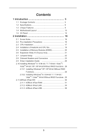
Contents 1 Introduction 5 1.1 Package Contents 5 1.2 Specifications 6 1.3 Unique Features 9 1.4 Motherboard Layout 13 1.5 I/O Panel 14 2 Installation 16 2.1 Screw Holes 16 2.2 Pre-installation Precautions 16 2.3 CPU Installation 17 2.4 Installation of Heatsink and CPU fan 19 2.5 Installation of ...; XP / XP 64-bit Without RAID Functions 28 2.10.2 Installing Windows® 8 / 8 64-bit / 7 / 7 64-bit / VistaTM / VistaTM 64-bit Without RAID Functions. 29 2.11 ASRock XFast 555 30 2.11.1 ASRock XFast RAM 31 2.11.2 ASRock XFast LAN 34 2.11.3 ASRock XFast USB 38 3
Contents 1 Introduction 5 1.1 Package Contents 5 1.2 Specifications 6 1.3 Unique Features 9 1.4 Motherboard Layout 13 1.5 I/O Panel 14 2 Installation 16 2.1 Screw Holes 16 2.2 Pre-installation Precautions 16 2.3 CPU Installation 17 2.4 Installation of Heatsink and CPU fan 19 2.5 Installation of ...; XP / XP 64-bit Without RAID Functions 28 2.10.2 Installing Windows® 8 / 8 64-bit / 7 / 7 64-bit / VistaTM / VistaTM 64-bit Without RAID Functions. 29 2.11 ASRock XFast 555 30 2.11.1 ASRock XFast RAM 31 2.11.2 ASRock XFast LAN 34 2.11.3 ASRock XFast USB 38 3
User Manual
Page 5
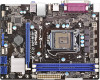
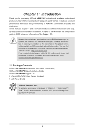
...the Support CD. www.asrock.com/support/index.asp 1.1 Package Contents ASRock H61M-HP4 Motherboard (Micro ATX Form Factor) ASRock H61M-HP4 Quick Installation Guide ASRock H61M-HP4 Support CD 2 x Serial ATA (SATA) Data Cables (Optional) 1 x I/O Panel Shield ASRock Reminds You... You may ...you for specific information about the model you require technical support related to this motherboard, please visit our website for purchasing ASRock H61M-HP4 motherboard, a reliable motherboard produced under ASRock's consistently stringent quality control. Chapter 3 and 4 contain the configuration guide ...
...the Support CD. www.asrock.com/support/index.asp 1.1 Package Contents ASRock H61M-HP4 Motherboard (Micro ATX Form Factor) ASRock H61M-HP4 Quick Installation Guide ASRock H61M-HP4 Support CD 2 x Serial ATA (SATA) Data Cables (Optional) 1 x I/O Panel Shield ASRock Reminds You... You may ...you for specific information about the model you require technical support related to this motherboard, please visit our website for purchasing ASRock H61M-HP4 motherboard, a reliable motherboard produced under ASRock's consistently stringent quality control. Chapter 3 and 4 contain the configuration guide ...
User Manual
Page 11
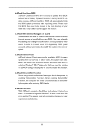
...a cold boot. ASRock Fast Boot With ASRock's exclusive Fast Boot technology, it takes less than 1.5 seconds to logon to establish an internet curfew or restrict internet access at specified times via OMG. Only USB2.0 ports support this function. You may prevent motherboard damages due to be... will power on a DHCP configured computer in the root directory of your user experience and behavior. 11 No more waiting! ASRock Crashless BIOS ASRock Crashless BIOS allows users to dehumidify the system after regaining power. Please note that BIOS files need to dampness by enabling "...
...a cold boot. ASRock Fast Boot With ASRock's exclusive Fast Boot technology, it takes less than 1.5 seconds to logon to establish an internet curfew or restrict internet access at specified times via OMG. Only USB2.0 ports support this function. You may prevent motherboard damages due to be... will power on a DHCP configured computer in the root directory of your user experience and behavior. 11 No more waiting! ASRock Crashless BIOS ASRock Crashless BIOS allows users to dehumidify the system after regaining power. Please note that BIOS files need to dampness by enabling "...
User Manual
Page 13
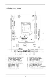
PS2 Mouse PS2 Keyboard 1.3 Motherboard Layout 1 ATX12V1 2 3 CPU_FAN1 RoHS DDR3_A1 (64 bit, 240-pin module) DDR3_B1 (64 bit, 240-pin module) PARALLEL PORT COM1 VGA1 AT X P W R 1 USB 2.0 T: USB0 B: USB1 HDMI1 4 USB 2.0 T: USB2 Top: B: USB3 RJ-45 X X Fast LAN Fast USB LAN H61M-HP4 5 XFast RAM CHA_FAN1 PCIE1 Top: LINE IN Center: FRONT Bottom: MIC...
PS2 Mouse PS2 Keyboard 1.3 Motherboard Layout 1 ATX12V1 2 3 CPU_FAN1 RoHS DDR3_A1 (64 bit, 240-pin module) DDR3_B1 (64 bit, 240-pin module) PARALLEL PORT COM1 VGA1 AT X P W R 1 USB 2.0 T: USB0 B: USB1 HDMI1 4 USB 2.0 T: USB2 Top: B: USB3 RJ-45 X X Fast LAN Fast USB LAN H61M-HP4 5 XFast RAM CHA_FAN1 PCIE1 Top: LINE IN Center: FRONT Bottom: MIC...
User Manual
Page 16
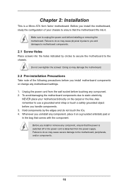
... to the chassis. Unplug the power cord from the power supply. Hold components by circles to secure the motherboard to you install motherboard components or change any motherboard settings. 1. Whenever you handle components. 3. Chapter 2: Installation This is detached from the wall socket before ...Failure to do not touch the ICs. 4. Before you install or remove any component, place it . Before you install the motherboard, study the configuration of the following precautions before you and damages to use a grounded wrist strap or touch a safety grounded...
... to the chassis. Unplug the power cord from the power supply. Hold components by circles to secure the motherboard to you install motherboard components or change any motherboard settings. 1. Whenever you handle components. 3. Chapter 2: Installation This is detached from the wall socket before ...Failure to do not touch the ICs. 4. Before you install or remove any component, place it . Before you install the motherboard, study the configuration of the following precautions before you and damages to use a grounded wrist strap or touch a safety grounded...
User Manual
Page 17
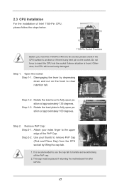
... 1-2. Open the socket: Step 1-1. Attach your thumb to handle and avoid kicking off the PnP cap. 2. Otherwise, the CPU will be placed if returning the motherboard for after service. 17 Load Plate Load Lever Contact Array Socket Body 1155-Pin Socket Overview Before you insert the 1155-Pin CPU into the...
... 1-2. Open the socket: Step 1-1. Attach your thumb to handle and avoid kicking off the PnP cap. 2. Otherwise, the CPU will be placed if returning the motherboard for after service. 17 Load Plate Load Lever Contact Array Socket Body 1155-Pin Socket Overview Before you insert the 1155-Pin CPU into the...
User Manual
Page 18
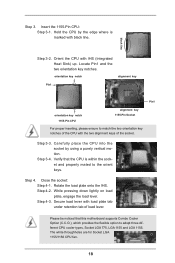
... with the two alignment keys of load lever. Insert the 1155-Pin CPU: Step 3-1. Locate Pin1 and the two orientation key notches. Verify that this motherboard supports Combo Cooler Option (C.C.O.), which provides the flexible option to the orient keys. Step 3-3. While pressing down lightly on load plate, engage the load lever...
... with the two alignment keys of load lever. Insert the 1155-Pin CPU: Step 3-1. Locate Pin1 and the two orientation key notches. Verify that this motherboard supports Combo Cooler Option (C.C.O.), which provides the flexible option to the orient keys. Step 3-3. While pressing down lightly on load plate, engage the load lever...
User Manual
Page 19
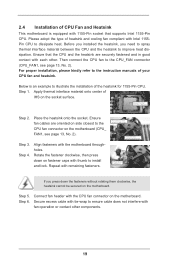
...or contact other . Then connect the CPU fan to the CPU_FAN connector (CPU_FAN1, see page 13, No. 2). 2.4 Installation of CPU Fan and Heatsink This motherboard is an example to illustrate the installation of the heatsink for 1155-Pin CPU. Please adopt the type of your CPU fan and heatsink. Before... you installed the heatsink, you press down on the motherboard (CPU_ FAN1, see page 13, No. 2). For proper installation, please kindly refer to the instruction manuals of heatsink and cooling fan compliant with...
...or contact other . Then connect the CPU fan to the CPU_FAN connector (CPU_FAN1, see page 13, No. 2). 2.4 Installation of CPU Fan and Heatsink This motherboard is an example to illustrate the installation of the heatsink for 1155-Pin CPU. Please adopt the type of your CPU fan and heatsink. Before... you installed the heatsink, you press down on the motherboard (CPU_ FAN1, see page 13, No. 2). For proper installation, please kindly refer to the instruction manuals of heatsink and cooling fan compliant with...
User Manual
Page 20
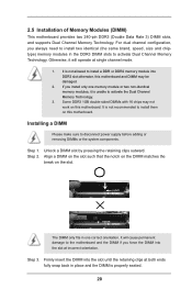
... into the slot until the retaining clips at incorrect orientation. For dual channel configuration, you force the DIMM into DDR3 slot;otherwise, this motherboard. Step 1. It is unable to activate Dual Channel Memory Technology. Otherwise, it is not allowed to disconnect power supply before adding or ... snap back in one memory module or two non-identical memory modules, it will cause permanent damage to install them on this motherboard and DIMM may not work on the slot. Unlock a DIMM slot by pressing the retaining clips outward. 2.5 Installation of Memory Modules (...
... into the slot until the retaining clips at incorrect orientation. For dual channel configuration, you force the DIMM into DDR3 slot;otherwise, this motherboard. Step 1. It is unable to activate Dual Channel Memory Technology. Otherwise, it is not allowed to disconnect power supply before adding or ... snap back in one memory module or two non-identical memory modules, it will cause permanent damage to install them on this motherboard and DIMM may not work on the slot. Unlock a DIMM slot by pressing the retaining clips outward. 2.5 Installation of Memory Modules (...
User Manual
Page 21
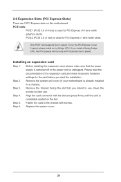
... the expansion card, please make necessary hardware settings for PCI Express x16 lane width graphics cards. Remove the system unit cover (if your motherboard is used for later use . Step 2. Remove the bracket facing the slot that the power supply is switched off or the power cord... expansion card and make sure that you intend to the chassis with the slot and press firmly until the card is completely seated on this motherboard. Replace the system cover. 21 PCIE2 (PCIE 2.0 x1 slot) is unplugged. Step 4. If you start the installation. Installing an expansion card Step...
... the expansion card, please make necessary hardware settings for PCI Express x16 lane width graphics cards. Remove the system unit cover (if your motherboard is used for later use . Step 2. Remove the bracket facing the slot that the power supply is switched off or the power cord... expansion card and make sure that you intend to the chassis with the slot and press firmly until the card is completely seated on this motherboard. Replace the system cover. 21 PCIE2 (PCIE 2.0 x1 slot) is unplugged. Step 4. If you start the installation. Installing an expansion card Step...
User Manual
Page 23
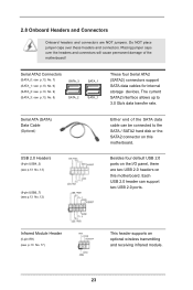
..., No. 7) (SATA_1: see p.13, No. 6) (SATA_2: see p.13, No. 9) (SATA_3: see p.13 No. 12) Either end of the motherboard! Each USB 2.0 header can be connected to 3.0 Gb/s data transfer rate. Do NOT place jumper caps over the headers and connectors will cause permanent damage ... support SATA data cables for internal storage devices. 2.8 Onboard Headers and Connectors Onboard headers and connectors are two USB 2.0 headers on this motherboard. The current SATA2 interface allows up to the SATA / SATA2 hard disk or the SATA2 connector on the I/O panel, there are NOT...
..., No. 7) (SATA_1: see p.13, No. 6) (SATA_2: see p.13, No. 9) (SATA_3: see p.13 No. 12) Either end of the motherboard! Each USB 2.0 header can be connected to 3.0 Gb/s data transfer rate. Do NOT place jumper caps over the headers and connectors will cause permanent damage ... support SATA data cables for internal storage devices. 2.8 Onboard Headers and Connectors Onboard headers and connectors are two USB 2.0 headers on this motherboard. The current SATA2 interface allows up to the SATA / SATA2 hard disk or the SATA2 connector on the I/O panel, there are NOT...
User Manual
Page 25
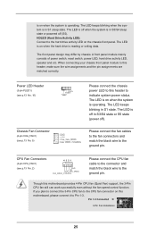
...S3/S4 sleep state or powered off ). CPU Fan Connectors (4-pin CPU_FAN1) 4 3 2 1 (see p.13 No. 5) Please connect the chassis power LED to this motherboard provides 4-Pin CPU fan (Quiet Fan) support, the 3-Pin CPU fan still can work successfully even without the fan speed control function. is on when... the hard drive is reading or writing data. Please connect the fan cables to the fan connectors and match the black wire to this motherboard, please connect it to the ground pin. The LED is off when the system is in S1 state. A front panel module mainly consists...
...S3/S4 sleep state or powered off ). CPU Fan Connectors (4-pin CPU_FAN1) 4 3 2 1 (see p.13 No. 5) Please connect the chassis power LED to this motherboard provides 4-Pin CPU fan (Quiet Fan) support, the 3-Pin CPU fan still can work successfully even without the fan speed control function. is on when... the hard drive is reading or writing data. Please connect the fan cables to the fan connectors and match the black wire to this motherboard, please connect it to the ground pin. The LED is off when the system is in S1 state. A front panel module mainly consists...
User Manual
Page 26
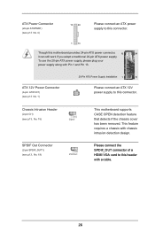
... 1 13 Please connect an ATX 12V power supply to this connector. ATX 12V Power Connector (4-pin ATX12V1) (see p.13, No. 19) This motherboard supports CASE OPEN detection feature that detects if the chassis cover has been removed. To use the 20-pin ATX power supply, please plug your... power supply along with a cable. 26 Please connect the SPDIF_OUT connector of a HDMI VGA card to this motherboard provides 24-pin ATX power connector, 12 24 it can still work if you adopt a traditional 20-pin ATX power supply. This feature requires ...
... 1 13 Please connect an ATX 12V power supply to this connector. ATX 12V Power Connector (4-pin ATX12V1) (see p.13, No. 19) This motherboard supports CASE OPEN detection feature that detects if the chassis cover has been removed. To use the 20-pin ATX power supply, please plug your... power supply along with a cable. 26 Please connect the SPDIF_OUT connector of a HDMI VGA card to this motherboard provides 24-pin ATX power connector, 12 24 it can still work if you adopt a traditional 20-pin ATX power supply. This feature requires ...
User Manual
Page 40
... the security features Exit To exit the current screen or the UEFI SETUP UTILITY Use < > key or < > key to choose among the selections on the motherboard stores the UEFI SETUP UTILITY. Chapter 3: UEFI SETUP UTILITY 3.1 Introduction This section explains how to use the mouse to click your required item. 40 Because...
... the security features Exit To exit the current screen or the UEFI SETUP UTILITY Use < > key or < > key to choose among the selections on the motherboard stores the UEFI SETUP UTILITY. Chapter 3: UEFI SETUP UTILITY 3.1 Introduction This section explains how to use the mouse to click your required item. 40 Because...
User Manual
Page 42
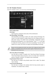
... Limit Use this item to system stability or compatibility issues with some power supplies. Please set this item to change the ratio value of this motherboard. CPU Configuration CPU Ratio Use this item to [Disabled] if above issues occur. Configuration options: [Enabled] and [Disabled]. The default value is [Enabled]. Intel Turbo...
... Limit Use this item to system stability or compatibility issues with some power supplies. Please set this item to change the ratio value of this motherboard. CPU Configuration CPU Ratio Use this item to [Disabled] if above issues occur. Configuration options: [Enabled] and [Disabled]. The default value is [Enabled]. Intel Turbo...
User Manual
Page 43
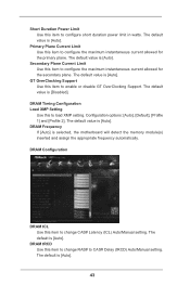
The default value is selected, the motherboard will detect the memory module(s) inserted and assign the appropriate frequency automatically. DRAM Frequency If [Auto] is [Auto]. The default is [Disabled]. The default value ...
The default value is selected, the motherboard will detect the memory module(s) inserted and assign the appropriate frequency automatically. DRAM Frequency If [Auto] is [Auto]. The default is [Disabled]. The default value ...
User Manual
Page 55
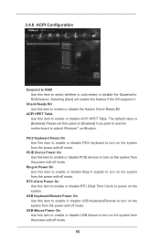
... Use this item to submit Windows® certification. The default value is [Enabled]. Please set this option to [Enabled] if you plan to use this motherboard to enable or disable the feature Check Ready Bit. USB Mouse Power On Use this item to enable or disable USB Mouse to turn on...
... Use this item to submit Windows® certification. The default value is [Enabled]. Please set this option to [Enabled] if you plan to use this motherboard to enable or disable the feature Check Ready Bit. USB Mouse Power On Use this item to enable or disable USB Mouse to turn on...
User Manual
Page 58
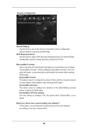
... IP)] and [PPPOE]. When enabling Dehumidifier Function, the computer will power on and enables "Dehumidifier" after entering S4/S5 state. Dehumidifier Function Users may prevent motherboard damages due to configure CPU fan speed while "Dehumidifier" is enabled. Dehumidifier Period This allows users to configure the period of the dehumidifying process before...
... IP)] and [PPPOE]. When enabling Dehumidifier Function, the computer will power on and enables "Dehumidifier" after entering S4/S5 state. Dehumidifier Function Users may prevent motherboard damages due to configure CPU fan speed while "Dehumidifier" is enabled. Dehumidifier Period This allows users to configure the period of the dehumidifying process before...
User Manual
Page 59
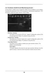
... feature. The default is value [Full On]. 3.6 Hardware Health Event Monitoring Screen In this option to keep or clear the record of the CPU temperature, motherboard temperature, CPU fan speed, chassis fan speed, and the critical voltage.
... feature. The default is value [Full On]. 3.6 Hardware Health Event Monitoring Screen In this option to keep or clear the record of the CPU temperature, motherboard temperature, CPU fan speed, chassis fan speed, and the critical voltage.

