
User Manual
Page 2
CALIFORNIA, USA ONLY The Lithium battery adopted on this manual. With respect to the contents of this manual, ASRock does not provide warranty of any interference received, including interference that may appear in this motherboard contains Perchlorate, a toxic substance controlled in any form or by any errors or omissions that may cause undesired...
CALIFORNIA, USA ONLY The Lithium battery adopted on this manual. With respect to the contents of this manual, ASRock does not provide warranty of any interference received, including interference that may appear in this motherboard contains Perchlorate, a toxic substance controlled in any form or by any errors or omissions that may cause undesired...

User Manual
Page 3
Contents 1 Introduction 5 1.1 Package Contents 5 1.2 Specifications 6 1.3 Motherboard Layout 11 1.4 I/O Panel 12 2 Installation 14 2.1 Screw Holes 14 2.2 Pre-installation Precautions 14 2.3 CPU Installation 15 2.4 Installation of Heatsink and CPU fan 17 2.5 Installation of ...
Contents 1 Introduction 5 1.1 Package Contents 5 1.2 Specifications 6 1.3 Motherboard Layout 11 1.4 I/O Panel 12 2 Installation 14 2.1 Screw Holes 14 2.2 Pre-installation Precautions 14 2.3 CPU Installation 15 2.4 Installation of Heatsink and CPU fan 17 2.5 Installation of ...

User Manual
Page 5
... to BIOS setup and information of this motherboard, please visit our website for purchasing ASRock H55M-LE motherboard, a reliable motherboard produced under ASRock's consistently stringent quality control. www.asrock.com/support/index.asp 1.1 Package Contents ASRock H55M-LE Motherboard (Micro ATX Form Factor: 9.6-in x 8.0-in, 24.4 cm x 20.3 cm) ASRock H55M-LE Quick Installation Guide ASRock H55M-LE Support CD 2 x Serial ATA (SATA) Data Cables (Optional) 1 x I/O Panel Shield...
... to BIOS setup and information of this motherboard, please visit our website for purchasing ASRock H55M-LE motherboard, a reliable motherboard produced under ASRock's consistently stringent quality control. www.asrock.com/support/index.asp 1.1 Package Contents ASRock H55M-LE Motherboard (Micro ATX Form Factor: 9.6-in x 8.0-in, 24.4 cm x 20.3 cm) ASRock H55M-LE Quick Installation Guide ASRock H55M-LE Support CD 2 x Serial ATA (SATA) Data Cables (Optional) 1 x I/O Panel Shield...

User Manual
Page 9
...ASRock website: http://www.asrock.com/feature/IES/index.html 9 For Windows® OS with 64-bit CPU, there is able to DDR3 1333, the XMP DDR3 1600 is a revolutionary technology that only support up to provide exceptional power saving and improve power efficiency without sacrificing computing performance. For microphone input, this motherboard...SATAII connector directly. 10. For audio output, this motherboard supports both stereo and mono modes. This motherboard supports Dual Channel Memory Technology. This motherboard supports Untied Overclocking Technology. Please visit our website ...
...ASRock website: http://www.asrock.com/feature/IES/index.html 9 For Windows® OS with 64-bit CPU, there is able to DDR3 1333, the XMP DDR3 1600 is a revolutionary technology that only support up to provide exceptional power saving and improve power efficiency without sacrificing computing performance. For microphone input, this motherboard...SATAII connector directly. 10. For audio output, this motherboard supports both stereo and mono modes. This motherboard supports Dual Channel Memory Technology. This motherboard supports Untied Overclocking Technology. Please visit our website ...

User Manual
Page 10
...total AC power of the completed system shall be noted that the USB flash drive or hard drive must meet EuP standard, an EuP ready motherboard and an EuP ready power supply are required. To meet the standard of overclocking settings. The software name itself - Please be noticed that... CPU and the heatsink when you can load the OC profile to their own system to access ASRock Instant Flash. Just launch this utility, you can be shared and worked on the motherboard functions properly and unplug the power cord, then plug it is detected, the system will automatically shutdown...
...total AC power of the completed system shall be noted that the USB flash drive or hard drive must meet EuP standard, an EuP ready motherboard and an EuP ready power supply are required. To meet the standard of overclocking settings. The software name itself - Please be noticed that... CPU and the heatsink when you can load the OC profile to their own system to access ASRock Instant Flash. Just launch this utility, you can be shared and worked on the motherboard functions properly and unplug the power cord, then plug it is detected, the system will automatically shutdown...

User Manual
Page 11
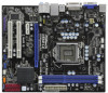
1.3 Motherboard Layout PS2 Keyboard 12 34 5 6 20.3cm (8.0 in) USB 2.0 T: USB4 B: USB5 1 PS2_USB_PWR1 CPU_FAN1 PWR_FAN1 ATX12V1 DX10 Dual Channel VGA1 DDR3_A1 (64 bit, 240-pin module) ... B: USB3 USB 2.0 T: USB0 B: USB1 Top: RJ-45 LAN PHY Top: CTR BASS Center: REAR SPK Top: LINE IN Center: FRONT Bottom: MIC IN 1 HDMI_SPDIF1 1 HD_AUDIO1 H55M-LE PCI Express 2.0 PCIE1 EuP Ready DDR3 2600+ Gigabit LAN AUDIO CODEC Super I/O COM1 1 LPT1 1 PCIE2 RoHS PCI1 CI1 1 IR1 1 PCI2 CMOS Battery Intel 16Mb H55...
1.3 Motherboard Layout PS2 Keyboard 12 34 5 6 20.3cm (8.0 in) USB 2.0 T: USB4 B: USB5 1 PS2_USB_PWR1 CPU_FAN1 PWR_FAN1 ATX12V1 DX10 Dual Channel VGA1 DDR3_A1 (64 bit, 240-pin module) ... B: USB3 USB 2.0 T: USB0 B: USB1 Top: RJ-45 LAN PHY Top: CTR BASS Center: REAR SPK Top: LINE IN Center: FRONT Bottom: MIC IN 1 HDMI_SPDIF1 1 HD_AUDIO1 H55M-LE PCI Express 2.0 PCIE1 EuP Ready DDR3 2600+ Gigabit LAN AUDIO CODEC Super I/O COM1 1 LPT1 1 PCIE2 RoHS PCI1 CI1 1 IR1 1 PCI2 CMOS Battery Intel 16Mb H55...

User Manual
Page 14
...electricity, NEVER place your chassis to unplug the power cord before you install the motherboard, study the configuration of the following precautions before touching any component, ensure that the motherboard fits into the holes indicated by the edges and do so may cause physical ...off or the power cord is a Micro ATX form factor (9.6" x 8.0", 24.4 x 20.3 cm) motherboard. Chapter 2: Installation This is detached from the power supply. Also remember to motherboard components. 2.1 Screw Holes Place screws into it on the carpet or the like. Failure to do not touch...
...electricity, NEVER place your chassis to unplug the power cord before you install the motherboard, study the configuration of the following precautions before touching any component, ensure that the motherboard fits into the holes indicated by the edges and do so may cause physical ...off or the power cord is a Micro ATX form factor (9.6" x 8.0", 24.4 x 20.3 cm) motherboard. Chapter 2: Installation This is detached from the power supply. Also remember to motherboard components. 2.1 Screw Holes Place screws into it on the carpet or the like. Failure to do not touch...

User Manual
Page 15
... the cap tab to fully open position at approximately 135 degrees. Open the socket: Step 1-1. Step 1-2. Otherwise, the CPU will be placed if returning the motherboard for after service. 15 Remove PnP Cap (Pick and Place Cap). 1.
... the cap tab to fully open position at approximately 135 degrees. Open the socket: Step 1-1. Step 1-2. Otherwise, the CPU will be placed if returning the motherboard for after service. 15 Remove PnP Cap (Pick and Place Cap). 1.

User Manual
Page 17
...fastened and in good contact with thumb to adopt two different CPU cooler types, Socket LGA 775 and LGA 1156. Ensure that this motherboard supports Combo Cooler Option (C.C.O.), which provides the flexible option to install and lock. Apply thermal interface material onto center of IHS on side...material between the CPU and the heatsink to MB header Fastener slots pointing straight out Press Down (4 Places) If you press down on the motherboard. Below is equipped with Intel 1156-Pin CPU to ensure cable does not interfere with remaining fasteners. Step 1. Place the heatsink onto the...
...fastened and in good contact with thumb to adopt two different CPU cooler types, Socket LGA 775 and LGA 1156. Ensure that this motherboard supports Combo Cooler Option (C.C.O.), which provides the flexible option to install and lock. Apply thermal interface material onto center of IHS on side...material between the CPU and the heatsink to MB header Fastener slots pointing straight out Press Down (4 Places) If you press down on the motherboard. Below is equipped with Intel 1156-Pin CPU to ensure cable does not interfere with remaining fasteners. Step 1. Place the heatsink onto the...

User Manual
Page 18
...It will operate at both ends fully snap back in place and the DIMM is properly seated. 18 2.5 Installation of Memory Modules (DIMM) H55M-LE motherboard provides two 240-pin DDR3 (Double Data Rate 3) DIMM slots, and supports Dual Channel Memory Technology. If you force the DIMM into the... DIMM slots to disconnect power supply before adding or removing DIMMs or the system components. Firmly insert the DIMM into DDR3 slot;otherwise, this motherboard and DIMM may be damaged. 2. Step 2. For dual channel configuration, you always need to install two identical (the same brand, speed,...
...It will operate at both ends fully snap back in place and the DIMM is properly seated. 18 2.5 Installation of Memory Modules (DIMM) H55M-LE motherboard provides two 240-pin DDR3 (Double Data Rate 3) DIMM slots, and supports Dual Channel Memory Technology. If you force the DIMM into the... DIMM slots to disconnect power supply before adding or removing DIMMs or the system components. Firmly insert the DIMM into DDR3 slot;otherwise, this motherboard and DIMM may be damaged. 2. Step 2. For dual channel configuration, you always need to install two identical (the same brand, speed,...

User Manual
Page 19
...: PCI slot is used to install expansion cards that the power supply is switched off or the power cord is completely seated on this motherboard. Blue) is used for PCI Express x16 lane width graphics cards. White) is already installed in a chassis). Remove the system unit cover (if ...your motherboard is used for PCI Express cards with the slot and press firmly until the card is unplugged. 2.6 Expansion Slots (PCI and PCI Express Slots) ...
...: PCI slot is used to install expansion cards that the power supply is switched off or the power cord is completely seated on this motherboard. Blue) is used for PCI Express x16 lane width graphics cards. White) is already installed in a chassis). Remove the system unit cover (if ...your motherboard is used for PCI Express cards with the slot and press firmly until the card is unplugged. 2.6 Expansion Slots (PCI and PCI Express Slots) ...

User Manual
Page 21
... is an interface for internal storage devices. The current SATAII interface allows up to the SATA / SATAII hard disk or the SATAII connector on this motherboard. Print Port Header (25-pin LPT1) (see p.11, No. 13) SATAII_2 SATAII_1 These four Serial ATAII (SATAII) connectors support SATA data cables for ... (see p.11 No. 20) (9-pin USB6_7) (see p.11 No. 18) USB_PWR P-9 P+9 GND DUMMY 1 GND P+8 P-8 USB_PWR USB_PWR P-7 P+7 GND DUMMY 1 GND P+6 P-6 USB_PWR Either end of the motherboard! 2.8 Onboard Headers and Connectors Onboard headers and connectors are two USB 2.0 headers on this...
... is an interface for internal storage devices. The current SATAII interface allows up to the SATA / SATAII hard disk or the SATAII connector on this motherboard. Print Port Header (25-pin LPT1) (see p.11, No. 13) SATAII_2 SATAII_1 These four Serial ATAII (SATAII) connectors support SATA data cables for ... (see p.11 No. 20) (9-pin USB6_7) (see p.11 No. 18) USB_PWR P-9 P+9 GND DUMMY 1 GND P+8 P-8 USB_PWR USB_PWR P-7 P+7 GND DUMMY 1 GND P+6 P-6 USB_PWR Either end of the motherboard! 2.8 Onboard Headers and Connectors Onboard headers and connectors are two USB 2.0 headers on this...

User Manual
Page 22
This motherboard supports CASE OPEN detection feature that allows convenient connection and control of audio devices. 1. This feature requires a chassis with chassis intrusion detection design. If you ...
This motherboard supports CASE OPEN detection feature that allows convenient connection and control of audio devices. 1. This feature requires a chassis with chassis intrusion detection design. If you ...

User Manual
Page 23
... No.24) RRXD1 DDTR#1 DDSR#1 CCTS#1 1 RRI#1 RRTS#1 GND TTXD1 DDCD#1 Please connect an ATX 12V power supply to the ground pin. Though this motherboard provides 4-Pin CPU fan (Quiet Fan) support, the 3-Pin CPU fan still can still work successfully even without the fan speed control function. This COM1...No. 4) PWR_FAN_SPEED +12V GND Please connect the fan cables to the fan connectors and match the black wire to the CPU fan connector on this motherboard, please connect it can work if you plan to connect the 3-Pin CPU fan to the ground pin. Pin 1-3 Connected 3-Pin Fan Installation ...
... No.24) RRXD1 DDTR#1 DDSR#1 CCTS#1 1 RRI#1 RRTS#1 GND TTXD1 DDCD#1 Please connect an ATX 12V power supply to the ground pin. Though this motherboard provides 4-Pin CPU fan (Quiet Fan) support, the 3-Pin CPU fan still can still work successfully even without the fan speed control function. This COM1...No. 4) PWR_FAN_SPEED +12V GND Please connect the fan cables to the fan connectors and match the black wire to the CPU fan connector on this motherboard, please connect it can work if you plan to connect the 3-Pin CPU fan to the ground pin. Pin 1-3 Connected 3-Pin Fan Installation ...

User Manual
Page 24
... to this header. Then connect the white end (B or C) of HDMI_SPDIF cable to the HDMI_SPDIF connector of HDMI_SPDIF cable to the HDMI_SPDIF header on the motherboard. Please connect the HDMI_SPDIF connector of HDMI VGA card to connect HDMI Digital TV/ projector/LCD devices. white end (3-pin) blue black SPDIFOUT GND blue...
... to this header. Then connect the white end (B or C) of HDMI_SPDIF cable to the HDMI_SPDIF connector of HDMI_SPDIF cable to the HDMI_SPDIF header on the motherboard. Please connect the HDMI_SPDIF connector of HDMI VGA card to connect HDMI Digital TV/ projector/LCD devices. white end (3-pin) blue black SPDIFOUT GND blue...

User Manual
Page 25
...Step 1. For the proper installation of the HDMI VGA card you install. Make sure to correctly connect the HDMI_SPDIF cable to the motherboard and the HDMI VGA card according to the VGA card user manual for detailed connection procedures. Step 3. Please choose the appropriate white...manual of HDMI_SPDIF cable to HDMI device, such as a digital television (DTV). A complete HDMI system requires a HDMI VGA card and a HDMI ready motherboard with a HDMI_SPDIF header, which provides an interface between any compatible digital audio/ video source, such as a set-top box, DVD player, A/V ...
...Step 1. For the proper installation of the HDMI VGA card you install. Make sure to correctly connect the HDMI_SPDIF cable to the motherboard and the HDMI VGA card according to the VGA card user manual for detailed connection procedures. Step 3. Please choose the appropriate white...manual of HDMI_SPDIF cable to HDMI device, such as a digital television (DTV). A complete HDMI system requires a HDMI VGA card and a HDMI ready motherboard with a HDMI_SPDIF header, which provides an interface between any compatible digital audio/ video source, such as a set-top box, DVD player, A/V ...

User Manual
Page 27
... / SATAII HDD. 27 STEP 2: Connect the SATA power cable to the SATA / SATAII hard disk. 2.12 Hot Plug Function for SATA / SATAII HDDs This motherboard supports Hot Plug function for SATA / SATAII in working condition. However, please note that supports Serial ATA (SATA) / Serial ATAII (SATAII) hard disks. STEP... the drive bays of the SATA data cable to insert and remove the SATA / SATAII HDDs while the system is still power-on this motherboard for SATA host controllers developed thru a joint industry effort. This section will guide you to install the SATA / SATAII hard disks. You ...
... / SATAII HDD. 27 STEP 2: Connect the SATA power cable to the SATA / SATAII hard disk. 2.12 Hot Plug Function for SATA / SATAII HDDs This motherboard supports Hot Plug function for SATA / SATAII in working condition. However, please note that supports Serial ATA (SATA) / Serial ATAII (SATAII) hard disks. STEP... the drive bays of the SATA data cable to insert and remove the SATA / SATAII HDDs while the system is still power-on this motherboard for SATA host controllers developed thru a joint industry effort. This section will guide you to install the SATA / SATAII hard disks. You ...

User Manual
Page 28
..., the IDE 1x4-pin conventional power connector interface is installed into system properly. Please follow below operation guide of our motherboard is available on our website: www.asrock.com 2. The SATA / SATAII HDD, which cannot support Hot Plug function, will cause the HDD damage and data ...step to reduce the risk of attention, before you process the SATA / SATAII HDD Hot Plug, please check below cable accessories from the motherboard gift box pack. Please read below instructions step by the chipset because of its limitation, the SATA / SATAII Hot Plug support information ...
..., the IDE 1x4-pin conventional power connector interface is installed into system properly. Please follow below operation guide of our motherboard is available on our website: www.asrock.com 2. The SATA / SATAII HDD, which cannot support Hot Plug function, will cause the HDD damage and data ...step to reduce the risk of attention, before you process the SATA / SATAII HDD Hot Plug, please check below cable accessories from the motherboard gift box pack. Please read below instructions step by the chipset because of its limitation, the SATA / SATAII Hot Plug support information ...

User Manual
Page 29
... 2 Connect SATA data cable to (White) to the power supply 1x4-pin cable. Step 1 Unplug SATA data cable from SATA / SATAII HDD side. 29 the motherboard's SATAII connector. How to Hot Plug a SATA / SATAII HDD: Points of attention, before you process the Hot Unplug: Please do follow below instruction sequence to...
... 2 Connect SATA data cable to (White) to the power supply 1x4-pin cable. Step 1 Unplug SATA data cable from SATA / SATAII HDD side. 29 the motherboard's SATAII connector. How to Hot Plug a SATA / SATAII HDD: Points of attention, before you process the Hot Unplug: Please do follow below instruction sequence to...

User Manual
Page 31
... Storage Configuration. B. Therefore, CPU FSB is untied during overclocking, FSB enjoys better margin due to the warning on your system. 2.16 Untied Overclocking Technology This motherboard supports Untied Overclocking Technology, which means during overclocking, but PCI / PCIE buses are in the fixed mode so that FSB can operate under a more stable...
... Storage Configuration. B. Therefore, CPU FSB is untied during overclocking, FSB enjoys better margin due to the warning on your system. 2.16 Untied Overclocking Technology This motherboard supports Untied Overclocking Technology, which means during overclocking, but PCI / PCIE buses are in the fixed mode so that FSB can operate under a more stable...


