
User Manual
Page 4
... 38 3.1 Introduction 38 3.1.1 BIOS Menu Bar 38 3.1.2 Navigation Keys 39 3.2 Main Screen 39 3.3 OC Tweaker Screen 40 3.4 Advanced Screen 44 3.4.1 CPU Configuration 45 3.4.2 Chipset Configuration 47 3.4.3 ACPI Configuration 49 3.4.4 ...
... 38 3.1 Introduction 38 3.1.1 BIOS Menu Bar 38 3.1.2 Navigation Keys 39 3.2 Main Screen 39 3.3 OC Tweaker Screen 40 3.4 Advanced Screen 44 3.4.1 CPU Configuration 45 3.4.2 Chipset Configuration 47 3.4.3 ACPI Configuration 49 3.4.4 ...

User Manual
Page 5
... step-by-step guide to quality and endurance. ASRock website http://www.asrock.com If you require technical support related to BIOS setup and information of this motherboard, please visit our website for specific information about the model you for purchasing ASRock H55 Extreme3 motherboard, a reliable motherboard produced under ASRock's consistently stringent quality control. You may find...
... step-by-step guide to quality and endurance. ASRock website http://www.asrock.com If you require technical support related to BIOS setup and information of this motherboard, please visit our website for specific information about the model you for purchasing ASRock H55 Extreme3 motherboard, a reliable motherboard produced under ASRock's consistently stringent quality control. You may find...

User Manual
Page 8
... ASRock Instant Flash (see CAUTION 13) - CPU Frequency Stepless Control (see CAUTION 15) - Good Night LED - CPU/Chassis/Power Fan Tachometer - CPU Quiet Fan - SMBIOS 2.3.1 Support - Turbo 50 / Turbo 100 GPU Overclocking (Requires Processor with LED BIOS Feature - 64Mb AMI Legal BIOS...Boot Failure Guard (B.F.G.) - Combo Cooler Option (C.C.O.) (see CAUTION 19) * For detailed product information, please visit our website: http://www.asrock.com 8 CPU/Chassis Fan Multi-Speed Control - CASE OPEN detection - Voltage Monitoring: +12V, +5V, +3.3V, CPU Vcore OS ...
... ASRock Instant Flash (see CAUTION 13) - CPU Frequency Stepless Control (see CAUTION 15) - Good Night LED - CPU/Chassis/Power Fan Tachometer - CPU Quiet Fan - SMBIOS 2.3.1 Support - Turbo 50 / Turbo 100 GPU Overclocking (Requires Processor with LED BIOS Feature - 64Mb AMI Legal BIOS...Boot Failure Guard (B.F.G.) - Combo Cooler Option (C.C.O.) (see CAUTION 19) * For detailed product information, please visit our website: http://www.asrock.com 8 CPU/Chassis Fan Multi-Speed Control - CASE OPEN detection - Voltage Monitoring: +12V, +5V, +3.3V, CPU Vcore OS ...

User Manual
Page 9
...risk involved with overclocking, including adjusting the setting in EDID. You can support the same features as HDMI port. 9. ASRock website: http://www.asrock.com/feature/OCTuner/index.htm 9 The maximum shared memory size is defined by the chipset vendor and is supported under Windows... cannot be enabled only if the display supports 12bpc in the BIOS, applying Untied Overclocking Technology, or using the thirdparty overclocking tools. Besides, with 64-bit CPU, there is a user-friendly ASRock overclocking tool which allows you implement Dual Channel Memory Technology, make...
...risk involved with overclocking, including adjusting the setting in EDID. You can support the same features as HDMI port. 9. ASRock website: http://www.asrock.com/feature/OCTuner/index.htm 9 The maximum shared memory size is defined by the chipset vendor and is supported under Windows... cannot be enabled only if the display supports 12bpc in the BIOS, applying Untied Overclocking Technology, or using the thirdparty overclocking tools. Besides, with 64-bit CPU, there is a user-friendly ASRock overclocking tool which allows you implement Dual Channel Memory Technology, make...

User Manual
Page 10
...Please be noted that the OC profile can press key during the POST or press key to BIOS setup menu to adopt two different CPU cooler types, Socket LGA 775 and LGA 1156. ASRock Instant Flash is capable of the completed system shall be shared and worked on the motherboard functions... properly and unplug the power cord, then plug it is a BIOS flash utility embedded in off mode condition. OC DNA, an ...
...Please be noted that the OC profile can press key during the POST or press key to BIOS setup menu to adopt two different CPU cooler types, Socket LGA 775 and LGA 1156. ASRock Instant Flash is capable of the completed system shall be shared and worked on the motherboard functions... properly and unplug the power cord, then plug it is a BIOS flash utility embedded in off mode condition. OC DNA, an ...

User Manual
Page 11
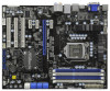
... DX10 Top: LINE IN Center: FRONT Bottom: MIC IN PCI Express 2.0 USB 3.0 SATA3 6Gb/s 40 PCIE1 H55 Extreme3 39 FRESCO FL1000G PCIE2 RoHS SATA3_1_2 SATAII_4_5 SATAII_2_3 SATAII_0_1 38 37 36 PCIE3 Super I/O PCIE4 PCI1 ErP/EuP Ready Design in Taipei ...Intel H55 Marvell 9123/ 9120 clr CMOS AUDIO CODEC HD_AUDIO1 1 HDMI_SPDIF1 1 COM1 1 PCI2 PCI3 CHA_FAN3 1 IR1 FRONT_1394 1 VIA VT6308S 1394a CMOS 64Mb BIOS RSTBTN Battery CLRCMOS1 1 CI1 1 PWRBTN USB_PWR3 SPEAKER1 1 USB7_8 1 USB9_10 1 ...
... DX10 Top: LINE IN Center: FRONT Bottom: MIC IN PCI Express 2.0 USB 3.0 SATA3 6Gb/s 40 PCIE1 H55 Extreme3 39 FRESCO FL1000G PCIE2 RoHS SATA3_1_2 SATAII_4_5 SATAII_2_3 SATAII_0_1 38 37 36 PCIE3 Super I/O PCIE4 PCI1 ErP/EuP Ready Design in Taipei ...Intel H55 Marvell 9123/ 9120 clr CMOS AUDIO CODEC HD_AUDIO1 1 HDMI_SPDIF1 1 COM1 1 PCI2 PCI3 CHA_FAN3 1 IR1 FRONT_1394 1 VIA VT6308S 1394a CMOS 64Mb BIOS RSTBTN Battery CLRCMOS1 1 CI1 1 PWRBTN USB_PWR3 SPEAKER1 1 USB7_8 1 USB9_10 1 ...

User Manual
Page 21
...". Jumper Setting PS2_USB_PWR1 1_2 2_3 Short pin2, pin3 to enable (see p.11, No. 23) 1_2 2_3 Default Clear CMOS Note: CLRCMOS1 allows you update the BIOS. Clear CMOS Jumper (CLRCMOS1) (see p.11, No. 1) +5V +5VSB +5VSB (standby) for USB23/45 +5V +5V_DUAL wake up the system under S3 (... for +5V +5VSB USB7_8/9_10/11_12 wake up events. USB_PWR2 1_2 Short pin2, pin3 to clear the CMOS when you just finish updating the BIOS, you must boot up the system first, and then shut it requires 2 Amp and higher standby current provided by power supply. Note: To select...
...". Jumper Setting PS2_USB_PWR1 1_2 2_3 Short pin2, pin3 to enable (see p.11, No. 23) 1_2 2_3 Default Clear CMOS Note: CLRCMOS1 allows you update the BIOS. Clear CMOS Jumper (CLRCMOS1) (see p.11, No. 1) +5V +5VSB +5VSB (standby) for USB23/45 +5V +5V_DUAL wake up the system under S3 (... for +5V +5VSB USB7_8/9_10/11_12 wake up events. USB_PWR2 1_2 Short pin2, pin3 to clear the CMOS when you just finish updating the BIOS, you must boot up the system first, and then shut it requires 2 Amp and higher standby current provided by power supply. Note: To select...

User Manual
Page 22
... internal storage devices. Placing jumper caps over these headers and connectors. The current SATA3 interface allows up to 3.0 Gb/s data transfer rate. Please adjust the BIOS option "Clear Status" to clear the record of the SATA data cable can be detected. Either end of previous chassis intrusion status. 2.8 Onboard Headers and...
... internal storage devices. Placing jumper caps over these headers and connectors. The current SATA3 interface allows up to 3.0 Gb/s data transfer rate. Please adjust the BIOS option "Clear Status" to clear the record of the SATA data cable can be detected. Either end of previous chassis intrusion status. 2.8 Onboard Headers and...

User Manual
Page 24
... Configuration. Chassis Speaker Header (4-pin SPEAKER 1) (see p.11 No. 21) Power LED Header (3-pin PLED1) (see p.11 No. 24) 1 SPEAKER DUMMY DUMMY +5V 1 PLED- Enter BIOS Setup Utility. Please connect the chassis power LED to this header.
... Configuration. Chassis Speaker Header (4-pin SPEAKER 1) (see p.11 No. 21) Power LED Header (3-pin PLED1) (see p.11 No. 24) 1 SPEAKER DUMMY DUMMY +5V 1 PLED- Enter BIOS Setup Utility. Please connect the chassis power LED to this header.

User Manual
Page 28
... Set stack. Store the Uncompressed pointer for reading the Dr. Debug codes. Verify that may occur during the bootblock initialization portion of the BIOS: Checkpoint Before D1 D1 D0 D2 D3 D4 D5 D6 D7 D8 D9 DA Description Early chipset initialization is used to lower system memory and... control is disabled. CPUID information is enabled. Leaves all RAM below for future use in memory. If BIOS recovery is available. The Bootblock initialization code sets up from ROM to provide code information, which makes troubleshooting even easier...
... Set stack. Store the Uncompressed pointer for reading the Dr. Debug codes. Verify that may occur during the bootblock initialization portion of the BIOS: Checkpoint Before D1 D1 D0 D2 D3 D4 D5 D6 D7 D8 D9 DA Description Early chipset initialization is used to lower system memory and... control is disabled. CPUID information is enabled. Leaves all RAM below for future use in memory. If BIOS recovery is available. The Bootblock initialization code sets up from ROM to provide code information, which makes troubleshooting even easier...

User Manual
Page 29
...control for more information. See DIM Code Checkpoints section of checkpoints that have optional ROMs. Initializes all available language, BIOS logo, and Silent logo modules. Initialized CMOS as system timer. Initializes the CPU. Init Local APIC Set up boot... the Kernel Variable "wCMOSFlags." Testing and initialization of chipset registers. Initializes different devices. Uncompress and initialize any platform specific BIOS modules. Allocate memory for boot strap proccessor Early CPU Init Exit Initializes the 8042 compatible Key Board Controller. Disable Cache ...
...control for more information. See DIM Code Checkpoints section of checkpoints that have optional ROMs. Initializes all available language, BIOS logo, and Silent logo modules. Initialized CMOS as system timer. Initializes the CPU. Init Local APIC Set up boot... the Kernel Variable "wCMOSFlags." Testing and initialization of chipset registers. Initializes different devices. Uncompress and initialize any platform specific BIOS modules. Allocate memory for boot strap proccessor Early CPU Init Exit Initializes the 8042 compatible Key Board Controller. Disable Cache ...

User Manual
Page 30
... status and programs the KBD typematic rate. 75 Initialize Int-13 and prepare for IPL detection. 78 Initializes IPL devices controlled by BIOS and option ROMs. 7A Initializes remaining option ROMs. 7C Generate and write contents of chipset registers. 40 Detect different devices (Parallel...module. AA Uninstall POST INT1Ch vector and INT09h vector. A0 Check boot password if installed. AB Prepare BBS for error. 87 Execute BIOS setup if needed / requested. 8C Late POST initialization of chipset registers. 8D Build ACPI tables (if ACPI is supported) 8E Program...
... status and programs the KBD typematic rate. 75 Initialize Int-13 and prepare for IPL detection. 78 Initializes IPL devices controlled by BIOS and option ROMs. 7A Initializes remaining option ROMs. 7C Generate and write contents of chipset registers. 40 Detect different devices (Parallel...module. AA Uninstall POST INT1Ch vector and INT09h vector. A0 Check boot password if installed. AB Prepare BBS for error. 87 Execute BIOS setup if needed / requested. 8C Late POST initialization of chipset registers. 8D Build ACPI tables (if ACPI is supported) 8E Program...

User Manual
Page 36
AHCI mode is not supported under Windows® XP / XP 64-bit OS. Enter BIOS SETUP UTILITY Advanced screen Storage Configuration. B. Therefore, the drivers you install can be auto-detected... OS on your optical drive first. Using SATA / SATAII HDDs with NCQ function (AHCI mode) STEP 1: Set Up BIOS. Enter BIOS SETUP UTILITY Advanced screen Storage Configuration. 2.17 Driver Installation Guide To install the drivers to your system, please insert the ...A. Please follow below steps. Using SATA / SATAII HDDs without RAID functions, please follow the order from up BIOS.
AHCI mode is not supported under Windows® XP / XP 64-bit OS. Enter BIOS SETUP UTILITY Advanced screen Storage Configuration. B. Therefore, the drivers you install can be auto-detected... OS on your optical drive first. Using SATA / SATAII HDDs with NCQ function (AHCI mode) STEP 1: Set Up BIOS. Enter BIOS SETUP UTILITY Advanced screen Storage Configuration. 2.17 Driver Installation Guide To install the drivers to your system, please insert the ...A. Please follow below steps. Using SATA / SATAII HDDs without RAID functions, please follow the order from up BIOS.

User Manual
Page 37
A. Please refer to [IDE]. Enter BIOS SETUP UTILITY Advanced screen Storage Configuration. B. Set the option "SATA Operation Mode" to the warning on your system. 2.19 Untied Overclocking Technology This motherboard supports ...-bit / VistaTM / VistaTM 64-bit OS on page 9 for the possible overclocking risk before you enable Untied Overclocking function, please enter "Overclock Mode" option of BIOS setup to set the selection from [Auto] to fixed PCI / PCIE buses. Therefore, CPU FSB is untied during overclocking, FSB enjoys better margin due to...
A. Please refer to [IDE]. Enter BIOS SETUP UTILITY Advanced screen Storage Configuration. B. Set the option "SATA Operation Mode" to the warning on your system. 2.19 Untied Overclocking Technology This motherboard supports ...-bit / VistaTM / VistaTM 64-bit OS on page 9 for the possible overclocking risk before you enable Untied Overclocking function, please enter "Overclock Mode" option of BIOS setup to set the selection from [Auto] to fixed PCI / PCIE buses. Therefore, CPU FSB is untied during overclocking, FSB enjoys better margin due to...

User Manual
Page 38
... If you start up the security features Exit To exit the current screen or the BIOS SETUP UTILITY Use < > key or < > key to locate and load the Operating System Security To ...set up the computer. Because the BIOS software is constantly being updated, the following selections: Main To set up the system time/date... information OC Tweaker To set up overclocking features Advanced To set up the advanced BIOS features H/W Monitor To display current hardware status Boot To set up the default system device to ...
... If you start up the security features Exit To exit the current screen or the BIOS SETUP UTILITY Use < > key or < > key to locate and load the Operating System Security To ...set up the computer. Because the BIOS software is constantly being updated, the following selections: Main To set up the system time/date... information OC Tweaker To set up overclocking features Advanced To set up the advanced BIOS features H/W Monitor To display current hardware status Boot To set up the default system device to ...

User Manual
Page 39
... Main OC Tweaker Advanced H/W Monitor Boot Security Exit System Overview System Time System Date [14:00:09] [Mon 02/22/2010] BIOS Version : H55 Extreme3 P1.00 Processor Type : Intel (R) Core (TM) i5 CPU 670 @ 3.47GHz (64bit) Processor Speed : 3466MHz Microcode Update : 20652/9 Cache Size : 4096KB Total Memory DDR3_A2 ....54 (C) Copyright 1985-2005, American Megatrends, Inc. 3.1.2Navigation Keys Please check the following table for all the settings To save changes and exit the BIOS SETUP UTILITY To jump to the Exit Screen or exit the current screen 3.2 Main Screen When you enter the...
... Main OC Tweaker Advanced H/W Monitor Boot Security Exit System Overview System Time System Date [14:00:09] [Mon 02/22/2010] BIOS Version : H55 Extreme3 P1.00 Processor Type : Intel (R) Core (TM) i5 CPU 670 @ 3.47GHz (64bit) Processor Speed : 3466MHz Microcode Update : 20652/9 Cache Size : 4096KB Total Memory DDR3_A2 ....54 (C) Copyright 1985-2005, American Megatrends, Inc. 3.1.2Navigation Keys Please check the following table for all the settings To save changes and exit the BIOS SETUP UTILITY To jump to the Exit Screen or exit the current screen 3.2 Main Screen When you enter the...

User Manual
Page 40
... 40 Please note that overclocing may cause damage to your GPU and motherboard. Please note that delivers unparalleled power savings. Besides the BIOS option, you can also choose our Intelligent Energy Saver utility to enable this option to load CPU EZ overclocking setting. The default ... set this item to [Enabled]. The default value is a revolutionary technology that overclocing may cause damage to your CPU and motherboard. BIOS SETUP UTILITY Main OC Tweaker Advanced H/W Monitor Boot Security Exit OC Tweaker Settings Turbo 50 Load CPU EZ OC Setting Load Memory EZ...
... 40 Please note that overclocing may cause damage to your GPU and motherboard. Please note that delivers unparalleled power savings. Besides the BIOS option, you can also choose our Intelligent Energy Saver utility to enable this option to load CPU EZ overclocking setting. The default ... set this item to [Enabled]. The default value is a revolutionary technology that overclocing may cause damage to your CPU and motherboard. BIOS SETUP UTILITY Main OC Tweaker Advanced H/W Monitor Boot Security Exit OC Tweaker Settings Turbo 50 Load CPU EZ OC Setting Load Memory EZ...

User Manual
Page 42
... Timing Control DRAM tCL DRAM tRCD DRAM tRP DRAM tRAS DRAM tRFC DRAM tWR DRAM tWTR DRAM tRRD DRAM tRTP DRAM tFAW DRAM Command Rate BIOS SETUP UTILITY 9 [Auto] 9 [Auto] 9 [Auto] 24 [Auto] 74 [Auto] 10 [Auto] 5 [Auto] 4 [Auto] 5 [Auto] 20 [Auto] [Auto] DRAM tCL Min = 6 Max = 11 +F1 F9 F10...
... Timing Control DRAM tCL DRAM tRCD DRAM tRP DRAM tRAS DRAM tRFC DRAM tWR DRAM tWTR DRAM tRRD DRAM tRTP DRAM tFAW DRAM Command Rate BIOS SETUP UTILITY 9 [Auto] 9 [Auto] 9 [Auto] 24 [Auto] 74 [Auto] 10 [Auto] 5 [Auto] 4 [Auto] 5 [Auto] 20 [Auto] [Auto] DRAM tCL Min = 6 Max = 11 +F1 F9 F10...

User Manual
Page 44
... or hard drive, then you may set the configurations for CPU WARNING : Setting wrong values in this section may cause system to malfunction. ASRock Instant Flash ASRock Instant Flash is a BIOS flash utility embedded in a few clicks without entering operating systems first like MS-DOS or Windows®. 3.4 Advanced Screen In this section...
... or hard drive, then you may set the configurations for CPU WARNING : Setting wrong values in this section may cause system to malfunction. ASRock Instant Flash ASRock Instant Flash is a BIOS flash utility embedded in a few clicks without entering operating systems first like MS-DOS or Windows®. 3.4 Advanced Screen In this section...

User Manual
Page 45
...) can prevent data pages from the chipset. This option will be hidden if the current CPU does not support No-Excute Memory Protection. 3.4.1CPU Configuration BIOS SETUP UTILITY Advanced Configure advanded CPU settings Intel (R) Core (TM) i5 CPU 670 @ 3.47GHz Frequency :3.46GHz Cache L1 :256 KB Cache L2 :1024 KB Cache...
...) can prevent data pages from the chipset. This option will be hidden if the current CPU does not support No-Excute Memory Protection. 3.4.1CPU Configuration BIOS SETUP UTILITY Advanced Configure advanded CPU settings Intel (R) Core (TM) i5 CPU 670 @ 3.47GHz Frequency :3.46GHz Cache L1 :256 KB Cache L2 :1024 KB Cache...


