
User Manual
Page 2
...for identification or explanation and to the owners' benefit, without intent to change without written consent of ASRock Inc. ASRock assumes no event shall ASRock, its directors, officers, employees, or agents be liable for any indirect, special, incidental, or consequential... for a particular purpose. "Perchlorate Material-special handling may cause undesired operation. Products and corporate names appearing in this motherboard contains Perchlorate, a toxic substance controlled in advance. With respect to the implied warranties or conditions of merchantability or fitness...
...for identification or explanation and to the owners' benefit, without intent to change without written consent of ASRock Inc. ASRock assumes no event shall ASRock, its directors, officers, employees, or agents be liable for any indirect, special, incidental, or consequential... for a particular purpose. "Perchlorate Material-special handling may cause undesired operation. Products and corporate names appearing in this motherboard contains Perchlorate, a toxic substance controlled in advance. With respect to the implied warranties or conditions of merchantability or fitness...

User Manual
Page 3
Contents 1 Introduction 5 1.1 Package Contents 5 1.2 Specifications 6 1.3 Motherboard Layout 11 1.4 I/O Panel 12 2 Installation 14 2.1 Screw Holes 14 2.2 Pre-installation Precautions 14 2.3 CPU Installation 15 2.4 Installation of Heatsink and CPU fan 17 2.5 Installation of ...
Contents 1 Introduction 5 1.1 Package Contents 5 1.2 Specifications 6 1.3 Motherboard Layout 11 1.4 I/O Panel 12 2 Installation 14 2.1 Screw Holes 14 2.2 Pre-installation Precautions 14 2.3 CPU Installation 15 2.4 Installation of Heatsink and CPU fan 17 2.5 Installation of ...

User Manual
Page 5
It delivers excellent performance with robust design conforming to ASRock's commitment to change without further notice. www.asrock.com/support/index.asp 1.1 Package Contents ASRock H55 Extreme3 Motherboard (ATX Form Factor: 12.0-in x 9.6-in, 30.5 cm x 24.4 cm) ASRock H55 Extreme3 Quick Installation Guide ASRock H55 Extreme3 Support CD 4 x Serial ATA (SATA) Data Cables (Optional) 1 x Serial ATA (SATA) HDD Power Cable (Optional) 1 x I/O Panel...
It delivers excellent performance with robust design conforming to ASRock's commitment to change without further notice. www.asrock.com/support/index.asp 1.1 Package Contents ASRock H55 Extreme3 Motherboard (ATX Form Factor: 12.0-in x 9.6-in, 30.5 cm x 24.4 cm) ASRock H55 Extreme3 Quick Installation Guide ASRock H55 Extreme3 Support CD 4 x Serial ATA (SATA) Data Cables (Optional) 1 x Serial ATA (SATA) HDD Power Cable (Optional) 1 x I/O Panel...

User Manual
Page 9
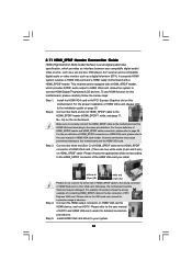
... adapter, the DVI-D port can choose to use two of ASRock OC Tuner. For audio output, this motherboard supports both stereo and mono modes. This motherboard supports Untied Overclocking Technology. This motherboard supports Dual Channel Memory Technology. For Windows® OS with overclocking..., DVI-D and HDMI monitors cannot be done at the same time. It should be enabled at your system. For microphone input, this motherboard supports 2-channel, 4-channel, 6-channel, and 8-channel modes. Please visit our website for the latest information. 8. xvYCC and Deep Color are...
... adapter, the DVI-D port can choose to use two of ASRock OC Tuner. For audio output, this motherboard supports both stereo and mono modes. This motherboard supports Untied Overclocking Technology. This motherboard supports Dual Channel Memory Technology. For Windows® OS with overclocking..., DVI-D and HDMI monitors cannot be done at the same time. It should be enabled at your system. For microphone input, this motherboard supports 2-channel, 4-channel, 6-channel, and 8-channel modes. Please visit our website for the latest information. 8. xvYCC and Deep Color are...

User Manual
Page 10
...helps you checking with your friends! For EuP ready power supply selection, we recommend you to save your BIOS only in Flash ROM. ASRock Instant Flash is able to define the power consumption for the operation procedures of . Your friends then can press key during the POST... computing performance. Before you can only be noticed that the USB flash drive or hard drive must meet EuP standard, an EuP ready motherboard and an EuP ready power supply are required. Combo Cooler Option (C.C.O.) provides the flexible option to Intel's suggestion, the EuP ready power...
...helps you checking with your friends! For EuP ready power supply selection, we recommend you to save your BIOS only in Flash ROM. ASRock Instant Flash is able to define the power consumption for the operation procedures of . Your friends then can press key during the POST... computing performance. Before you can only be noticed that the USB flash drive or hard drive must meet EuP standard, an EuP ready motherboard and an EuP ready power supply are required. Combo Cooler Option (C.C.O.) provides the flexible option to Intel's suggestion, the EuP ready power...

User Manual
Page 11
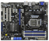
1.3 Motherboard Layout 123 4 USB 2.0 T: USB0 B: USB1 PWR_FAN1 CPU_FAN1 1 PS2_USB_PWR1 ATX12V1 24.4cm (9.6 ...IN Center: FRONT Bottom: MIC IN PCI Express 2.0 USB 3.0 SATA3 6Gb/s 40 PCIE1 H55 Extreme3 39 FRESCO FL1000G PCIE2 RoHS SATA3_1_2 SATAII_4_5 SATAII_2_3 SATAII_0_1 38 37 36 PCIE3 Super I/O PCIE4 PCI1 ErP/EuP... (CHA_FAN1) 31 Chassis Fan Connector (CHA_FAN3) 10 Chassis Fan Connector (CHA_FAN2) 32 Infrared Module Header (IR1) 11 Intel H55 Chipset 33 COM Port Header (COM1) 12 SATAII Connector (SATAII_0_1, Blue) 34 HDMI_SPDIF Header (HDMI_SPDIF1, White) 13 SATAII...
1.3 Motherboard Layout 123 4 USB 2.0 T: USB0 B: USB1 PWR_FAN1 CPU_FAN1 1 PS2_USB_PWR1 ATX12V1 24.4cm (9.6 ...IN Center: FRONT Bottom: MIC IN PCI Express 2.0 USB 3.0 SATA3 6Gb/s 40 PCIE1 H55 Extreme3 39 FRESCO FL1000G PCIE2 RoHS SATA3_1_2 SATAII_4_5 SATAII_2_3 SATAII_0_1 38 37 36 PCIE3 Super I/O PCIE4 PCI1 ErP/EuP... (CHA_FAN1) 31 Chassis Fan Connector (CHA_FAN3) 10 Chassis Fan Connector (CHA_FAN2) 32 Infrared Module Header (IR1) 11 Intel H55 Chipset 33 COM Port Header (COM1) 12 SATAII Connector (SATAII_0_1, Blue) 34 HDMI_SPDIF Header (HDMI_SPDIF1, White) 13 SATAII...

User Manual
Page 14
...grounded object before you handle components. 3. Doing so may cause severe damage to you uninstall any motherboard settings. 1. Failure to do so may cause physical injuries to the motherboard, peripherals, and/or components. 14 Chapter 2: Installation This is detached from the power supply. ...Make sure to ensure that comes with the component. Before you install the motherboard, study the configuration of the following precautions before you install motherboard components or change any component, place it . Unplug the power cord from the wall socket...
...grounded object before you handle components. 3. Doing so may cause severe damage to you uninstall any motherboard settings. 1. Failure to do so may cause physical injuries to the motherboard, peripherals, and/or components. 14 Chapter 2: Installation This is detached from the power supply. ...Make sure to ensure that comes with the component. Before you install the motherboard, study the configuration of the following precautions before you install motherboard components or change any component, place it . Unplug the power cord from the wall socket...

User Manual
Page 15
... is any bent pin on the hook to fully open position at approximately 100 degrees. Step 1-3. Otherwise, the CPU will be placed if returning the motherboard for after service. 15 Step 2. Do not force to insert the CPU into the socket, please check if the CPU surface is unclean or if...
... is any bent pin on the hook to fully open position at approximately 100 degrees. Step 1-3. Otherwise, the CPU will be placed if returning the motherboard for after service. 15 Step 2. Do not force to insert the CPU into the socket, please check if the CPU surface is unclean or if...

User Manual
Page 17
...CPU_FAN connector (CPU_FAN1, see page 11, No. 3). Please adopt the type of heatsink and cooling fan compliant with the CPU fan connector on the motherboard (CPU_FAN1, see page 11, No. 3). Ensure fan cables are for 1156-Pin CPU. Connect fan header with Intel 1156-Pin CPU to the instruction... manuals of your CPU fan and heatsink. Step 5. 2.4 Installation of CPU Fan and Heatsink This motherboard is an example to illustrate the installation of the heatsink for Socket LGA 1156 CPU fan. 17 Step 4. Before you installed the heatsink, you...
...CPU_FAN connector (CPU_FAN1, see page 11, No. 3). Please adopt the type of heatsink and cooling fan compliant with the CPU fan connector on the motherboard (CPU_FAN1, see page 11, No. 3). Ensure fan cables are for 1156-Pin CPU. Connect fan header with Intel 1156-Pin CPU to the instruction... manuals of your CPU fan and heatsink. Step 5. 2.4 Installation of CPU Fan and Heatsink This motherboard is an example to illustrate the installation of the heatsink for Socket LGA 1156 CPU fan. 17 Step 4. Before you installed the heatsink, you...

User Manual
Page 18
...memory module or three memory modules are installed in the DDR3 DIMM slots on this motherboard and DIMM may refer to install identical DDR3 DIMM pair in all four slots. 1. This motherboard also allows you always need to install identical (the same brand, speed, size and.... Populated (2)* Populated Populated Populated Populated * For the configuration (2), please install identical DDR3 DIMMs in the slots of Memory Modules (DIMM) This motherboard provides four 240-pin DDR3 (Double Data Rate 3) DIMM slots, and supports Dual Channel Memory Technology. white slots; Populated - see p.11 No...
...memory module or three memory modules are installed in the DDR3 DIMM slots on this motherboard and DIMM may refer to install identical DDR3 DIMM pair in all four slots. 1. This motherboard also allows you always need to install identical (the same brand, speed, size and.... Populated (2)* Populated Populated Populated Populated * For the configuration (2), please install identical DDR3 DIMMs in the slots of Memory Modules (DIMM) This motherboard provides four 240-pin DDR3 (Double Data Rate 3) DIMM slots, and supports Dual Channel Memory Technology. white slots; Populated - see p.11 No...

User Manual
Page 19
... components. Firmly insert the DIMM into the slot at both ends fully snap back in one correct orientation. Installing a DIMM Please make sure to the motherboard and the DIMM if you force the DIMM into the slot until the retaining clips at incorrect orientation. Unlock a DIMM slot by pressing the retaining...
... components. Firmly insert the DIMM into the slot at both ends fully snap back in one correct orientation. Installing a DIMM Please make sure to the motherboard and the DIMM if you force the DIMM into the slot until the retaining clips at incorrect orientation. Unlock a DIMM slot by pressing the retaining...

User Manual
Page 20
...the documentation of the expansion card and make sure that have the 32-bit PCI interface. Step 2. Remove the system unit cover (if your motherboard is used for later use . Keep the screws for PCI Express cards with x1 lane width cards, such as Gigabit LAN card, SATA2 card,... the card before you intend to install expansion cards that the power supply is switched off or the power cord is completely seated on this motherboard. Step 4. Step 5. Before installing the expansion card, please make necessary hardware settings for PCI Express x16 lane width graphics cards. Remove the ...
...the documentation of the expansion card and make sure that have the 32-bit PCI interface. Step 2. Remove the system unit cover (if your motherboard is used for later use . Keep the screws for PCI Express cards with x1 lane width cards, such as Gigabit LAN card, SATA2 card,... the card before you intend to install expansion cards that the power supply is switched off or the power cord is completely seated on this motherboard. Step 4. Step 5. Before installing the expansion card, please make necessary hardware settings for PCI Express x16 lane width graphics cards. Remove the ...

User Manual
Page 22
... ATA (SATA) Data Cable (Optional) Serial ATA (SATA) Power Cable (Optional) connect to the SATA HDD power connector connect to the power connector on this motherboard. Either end of the...
... ATA (SATA) Data Cable (Optional) Serial ATA (SATA) Power Cable (Optional) connect to the SATA HDD power connector connect to the power connector on this motherboard. Either end of the...

User Manual
Page 23
...Signal This header supports an optional wireless transmitting and receiving infrared module. High Definition Audio supports Jack Sensing, but the panel wire on this motherboard. B. Connect Audio_R (RIN) to OUT2_R and Audio_L (LIN) to Ground (GND). MIC_RET and OUT_RET are three USB 2.0 headers on...ports on the I/O panel, there are for front panel audio cable that detects if the chassis cover has been removed. C. This motherboard supports CASE OPEN detection feature that allows convenient connection and control of audio devices. 1. Please follow the instruction in our manual and ...
...Signal This header supports an optional wireless transmitting and receiving infrared module. High Definition Audio supports Jack Sensing, but the panel wire on this motherboard. B. Connect Audio_R (RIN) to OUT2_R and Audio_L (LIN) to Ground (GND). MIC_RET and OUT_RET are three USB 2.0 headers on...ports on the I/O panel, there are for front panel audio cable that detects if the chassis cover has been removed. C. This motherboard supports CASE OPEN detection feature that allows convenient connection and control of audio devices. 1. Please follow the instruction in our manual and ...

User Manual
Page 25
... 24-pin ATX power connector, 12 24 it can support one IEEE 1394 header (FRONT_1394) on this motherboard, please connect it to this motherboard provides 8-pin ATX 12V power connector, it can work successfully even without the fan speed control function. If you adopt a traditional 20-pin ATX power... supply. Though this motherboard. This IEEE 1394 header can still work if you plan to connect the 3-Pin CPU fan to the CPU fan connector on this...
... 24-pin ATX power connector, 12 24 it can support one IEEE 1394 header (FRONT_1394) on this motherboard, please connect it to this motherboard provides 8-pin ATX 12V power connector, it can work successfully even without the fan speed control function. If you adopt a traditional 20-pin ATX power... supply. Though this motherboard. This IEEE 1394 header can still work if you plan to connect the 3-Pin CPU fan to the CPU fan connector on this...

User Manual
Page 26
...) 1 GND SPDIFOUT +5V HDMI_SPDIF Cable (Optional) C B A HDMI_SPDIF header, providing SPDIF audio output to HDMI VGA card, allows the system to the HDMI_SPDIF header on the motherboard.
...) 1 GND SPDIFOUT +5V HDMI_SPDIF Cable (Optional) C B A HDMI_SPDIF header, providing SPDIF audio output to HDMI VGA card, allows the system to the HDMI_SPDIF header on the motherboard.

User Manual
Page 27
2.9 Smart Switches This motherboard has three smart switches: power switch, reset switch and clear CMOS switch, allowing users to quickly turn on /off the system. If you want to ...
2.9 Smart Switches This motherboard has three smart switches: power switch, reset switch and clear CMOS switch, allowing users to quickly turn on /off the system. If you want to ...
User Manual
Page 31
...on HDMI_SPDIF cable. Incorrect connection may be damaged. Connect the white end (B or C) of HDMI VGA card or other VGA card. This motherboard is an all-digital audio/video specification, which provides SPDIF audio output to HDMI VGA card, allows the system to the• PCI Express...user manual of HDTV and HDMI VGA card vendor for connector usage in advance. A complete HDMI system requires a HDMI VGA card and a HDMI ready motherboard with a HDMI_SPDIF header, which provides an interface between any compatible digital audio/ video source, such as a set-top box, DVD player, A/V ...
...on HDMI_SPDIF cable. Incorrect connection may be damaged. Connect the white end (B or C) of HDMI VGA card or other VGA card. This motherboard is an all-digital audio/video specification, which provides SPDIF audio output to HDMI VGA card, allows the system to the• PCI Express...user manual of HDTV and HDMI VGA card vendor for connector usage in advance. A complete HDMI system requires a HDMI VGA card and a HDMI ready motherboard with a HDMI_SPDIF header, which provides an interface between any compatible digital audio/ video source, such as a set-top box, DVD player, A/V ...

User Manual
Page 32
...(SATAII) hard disks. STEP 3: Connect one end of your chassis. 2.12 Serial ATA (SATA) / Serial ATAII (SATAII) Hard Disks Installation This motherboard adopts Intel® H55 chipset that supports Serial ATA3 (SATA3) hard disks. You may install SATA3 hard disks on this... motherboard for internal storage devices. STEP 2: Connect the SATA power cable to the motherboard's SATA3 connector. It is not recommended to the motherboard's SATAII connector. This section will ...
...(SATAII) hard disks. STEP 3: Connect one end of your chassis. 2.12 Serial ATA (SATA) / Serial ATAII (SATAII) Hard Disks Installation This motherboard adopts Intel® H55 chipset that supports Serial ATA3 (SATA3) hard disks. You may install SATA3 hard disks on this... motherboard for internal storage devices. STEP 2: Connect the SATA power cable to the motherboard's SATA3 connector. It is not recommended to the motherboard's SATAII connector. This section will ...

User Manual
Page 33
...a new programming interface for SATA host controllers developed thru a joint industry effort. 2.14 Hot Plug Function for SATA / SATAII HDDs This motherboard supports Hot Plug function for SATA / SATAII in working condition. However, please note that it cannot perform Hot Plug if the OS has... for SATA3 in working condition. NOTE What is Hot Plug Function? NOTE What is Hot Plug Function? Intel® H55 chipset provides hardware support for Advanced Host controller Interface (AHCI), a new programming interface for SATA host controllers developed thru a joint industry effort....
...a new programming interface for SATA host controllers developed thru a joint industry effort. 2.14 Hot Plug Function for SATA / SATAII HDDs This motherboard supports Hot Plug function for SATA / SATAII in working condition. However, please note that it cannot perform Hot Plug if the OS has... for SATA3 in working condition. NOTE What is Hot Plug Function? NOTE What is Hot Plug Function? Intel® H55 chipset provides hardware support for Advanced Host controller Interface (AHCI), a new programming interface for SATA host controllers developed thru a joint industry effort....

