
User Manual
Page 5
...1 1.2 Specifications 2 1.3 Motherboard Layout 6 1.4 I/O Panel 8 Chapter 2 Installation 10 2.1 Installing the CPU 11 2.2 Installing the CPU Fan and Heatsink 14 2.3 Installing Memory Modules (DIMM) 15 2.4 Expansion Slots (PCI Express Slots) 17 2.5 Jumpers Setup 18 2.6 Onboard Headers and Connectors 19 2.7 M.2_SSD (NGFF) Module Installation Guide (M2_1) 24 Chapter 3 Software and Utilities Operation 28 3.1 Installing Drivers 28 3.2 ASRock Motherboard Utility (A-Tuning) 29 3.2.1 Installing ASRock Motherboard Utility (A-Tuning) 29 3.2.2 Using ASRock Motherboard Utility...
...1 1.2 Specifications 2 1.3 Motherboard Layout 6 1.4 I/O Panel 8 Chapter 2 Installation 10 2.1 Installing the CPU 11 2.2 Installing the CPU Fan and Heatsink 14 2.3 Installing Memory Modules (DIMM) 15 2.4 Expansion Slots (PCI Express Slots) 17 2.5 Jumpers Setup 18 2.6 Onboard Headers and Connectors 19 2.7 M.2_SSD (NGFF) Module Installation Guide (M2_1) 24 Chapter 3 Software and Utilities Operation 28 3.1 Installing Drivers 28 3.2 ASRock Motherboard Utility (A-Tuning) 29 3.2.1 Installing ASRock Motherboard Utility (A-Tuning) 29 3.2.2 Using ASRock Motherboard Utility...

User Manual
Page 7
...for specific information about the model you for M.2 Socket (Optional) • 1 x I/O Panel Shield 1 English H510M-HDV/M.2 Chapter 1 Introduction Thank you are using. ASRock website http://www.asrock.com. 1.1 Package Contents • ASRock H510M-HDV/M.2 Motherboard (Micro ATX Form Factor) • ASRock H510M-HDV/M.2 Quick Installation Guide • ASRock H510M-HDV/M.2 Support CD • 2 x Serial ATA (SATA) Data Cables (Optional) • 1 x Screw for purchasing ASRock H510M-HDV/M.2 motherboard, a reliable motherboard produced under ASRock's consistently stringent quality control...
...for specific information about the model you for M.2 Socket (Optional) • 1 x I/O Panel Shield 1 English H510M-HDV/M.2 Chapter 1 Introduction Thank you are using. ASRock website http://www.asrock.com. 1.1 Package Contents • ASRock H510M-HDV/M.2 Motherboard (Micro ATX Form Factor) • ASRock H510M-HDV/M.2 Quick Installation Guide • ASRock H510M-HDV/M.2 Support CD • 2 x Serial ATA (SATA) Data Cables (Optional) • 1 x Screw for purchasing ASRock H510M-HDV/M.2 motherboard, a reliable motherboard produced under ASRock's consistently stringent quality control...

User Manual
Page 10
... LED and SPEED LED) • HD Audio Jacks: Line in / Front Speaker / Microphone Storage • 4 x SATA3 6.0 Gb/s Connectors, support Intel Rapid Storage Technology 18, NCQ, AHCI and Hot Plug • 1 x Ultra M.2 Socket (M2_1), supports M Key type 2260/2280 M.2 SATA3 6.0 Gb/s module and M.2 PCI Express module up to Gen3 x4 (32 Gb/s)* * Supports NVMe SSD as boot disks * Supports ASRock U.2 Kit Connector • 1 x COM Port Header • 1 x SPI TPM Header • 1 x Chassis Intrusion and Speaker Header • 1 x CPU Fan Connector (4-pin) * The CPU Fan Connector supports the CPU fan...
... LED and SPEED LED) • HD Audio Jacks: Line in / Front Speaker / Microphone Storage • 4 x SATA3 6.0 Gb/s Connectors, support Intel Rapid Storage Technology 18, NCQ, AHCI and Hot Plug • 1 x Ultra M.2 Socket (M2_1), supports M Key type 2260/2280 M.2 SATA3 6.0 Gb/s module and M.2 PCI Express module up to Gen3 x4 (32 Gb/s)* * Supports NVMe SSD as boot disks * Supports ASRock U.2 Kit Connector • 1 x COM Port Header • 1 x SPI TPM Header • 1 x Chassis Intrusion and Speaker Header • 1 x CPU Fan Connector (4-pin) * The CPU Fan Connector supports the CPU fan...
User Manual
Page 11
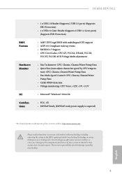
... Core/Cache, CPU GT, VCCSA, DRAM, VCCIO, VCCST, VCCIN AUX Voltage Multi-adjustment • Fan Tachometer: CPU, Chassis, Chassis/Water Pump Fans • Quiet Fan (Auto adjust chassis fan speed by overclocking. We are not responsible for possible damage caused by CPU tempera- H510M-HDV/M.2 BIOS Feature Hardware Monitor OS Certifications • 1 x USB 2.0 Header (Supports 2 USB 2.0 ports) (Supports ESD Protection) • 1 x USB 3.2 Gen1 Header (Supports 2 USB 3.2 Gen1 ports) (Supports ESD Protection) • AMI UEFI Legal BIOS with overclocking, including adjusting the setting...
... Core/Cache, CPU GT, VCCSA, DRAM, VCCIO, VCCST, VCCIN AUX Voltage Multi-adjustment • Fan Tachometer: CPU, Chassis, Chassis/Water Pump Fans • Quiet Fan (Auto adjust chassis fan speed by overclocking. We are not responsible for possible damage caused by CPU tempera- H510M-HDV/M.2 BIOS Feature Hardware Monitor OS Certifications • 1 x USB 2.0 Header (Supports 2 USB 2.0 ports) (Supports ESD Protection) • 1 x USB 3.2 Gen1 Header (Supports 2 USB 3.2 Gen1 ports) (Supports ESD Protection) • AMI UEFI Legal BIOS with overclocking, including adjusting the setting...

User Manual
Page 13
...12V Power Connector (ATX12V1) 2 CPU Fan Connector (CPU_FAN1) 3 2 x 288-pin DDR4 DIMM Slots (DDR4_A1, DDR4_B1) 4 Chassis Fan Connector (CHA_FAN2) 5 ATX Power Connector (ATXPWR1) 6 USB 3.2 Gen1 Header (USB3_3_4) 7 SATA3 Connector (SATA3_1)(Lower) 8 SATA3 Connector (SATA3_0)(Upper) 9 System Panel Header (PANEL1) 10 SATA3 Connector (SATA3_3) 11 SATA3 Connector (SATA3_2) 12 Clear CMOS Jumper (CLRMOS1) 13 SPI TPM Header (SPI_TPM_J1) 14 USB 2.0 Header (USB_5_6) 15 COM Port Header (COM1) 16 Chassis Intrusion and Speaker Header (SPK_CI1) 17 Front Panel Audio Header (HD_AUDIO1) 18 Chassis/Water Pump Fan...
...12V Power Connector (ATX12V1) 2 CPU Fan Connector (CPU_FAN1) 3 2 x 288-pin DDR4 DIMM Slots (DDR4_A1, DDR4_B1) 4 Chassis Fan Connector (CHA_FAN2) 5 ATX Power Connector (ATXPWR1) 6 USB 3.2 Gen1 Header (USB3_3_4) 7 SATA3 Connector (SATA3_1)(Lower) 8 SATA3 Connector (SATA3_0)(Upper) 9 System Panel Header (PANEL1) 10 SATA3 Connector (SATA3_3) 11 SATA3 Connector (SATA3_2) 12 Clear CMOS Jumper (CLRMOS1) 13 SPI TPM Header (SPI_TPM_J1) 14 USB 2.0 Header (USB_5_6) 15 COM Port Header (COM1) 16 Chassis Intrusion and Speaker Header (SPK_CI1) 17 Front Panel Audio Header (HD_AUDIO1) 18 Chassis/Water Pump Fan...

User Manual
Page 23
... card and make sure that the power supply is switched off or the power cord is used for the card before you start the installation. PCIE2 (PCIe 3.0 x1 slot) is used for PCI Express x1 lane width cards. 17 English PCIe slots: 11th Gen Intel® CoreTM Processors: PCIE1 (PCIe 4.0 x16 slot) is unplugged. Before installing an expansion card, please make necessary hardware settings for PCI Express x16 lane width graphics cards. H510M-HDV/M.2 2.4 Expansion Slots (PCI Express Slots) There are 2 PCI Express slots on the motherboard...
... card and make sure that the power supply is switched off or the power cord is used for the card before you start the installation. PCIE2 (PCIe 3.0 x1 slot) is used for PCI Express x1 lane width cards. 17 English PCIe slots: 11th Gen Intel® CoreTM Processors: PCIE1 (PCIe 4.0 x16 slot) is unplugged. Before installing an expansion card, please make necessary hardware settings for PCI Express x16 lane width graphics cards. H510M-HDV/M.2 2.4 Expansion Slots (PCI Express Slots) There are 2 PCI Express slots on the motherboard...

User Manual
Page 24
... not clear the CMOS right after clearing the CMOS. Clear CMOS Jumper (CLRMOS1) (see p.6, No. 12) 2-pin Jumper CLRMOS1 allows you clear the CMOS, the case open may be cleared only if the CMOS battery is "Short". Please be noted that the password, date, time, and user default profile will be detected. 2.5 Jumpers Setup The illustration shows how jumpers are setup. If you need to clear the CMOS when you just finish updating the BIOS, you must boot...
... not clear the CMOS right after clearing the CMOS. Clear CMOS Jumper (CLRMOS1) (see p.6, No. 12) 2-pin Jumper CLRMOS1 allows you clear the CMOS, the case open may be cleared only if the CMOS battery is "Short". Please be noted that the password, date, time, and user default profile will be detected. 2.5 Jumpers Setup The illustration shows how jumpers are setup. If you need to clear the CMOS when you just finish updating the BIOS, you must boot...

User Manual
Page 25
... panel. English 19 The front panel design may configure the way to the pin assignments below. Do NOT place jumper caps over the headers and connectors will cause permanent damage to the power switch on when the hard drive is in S4 sleep state or powered off (S5). H510M-HDV/M.2 2.6 Onboard Headers and Connectors Onboard headers and connectors are matched correctly. Note the positive and negative pins before connecting the cables. PWRBTN (Power Switch): Connect to the motherboard...
... panel. English 19 The front panel design may configure the way to the pin assignments below. Do NOT place jumper caps over the headers and connectors will cause permanent damage to the power switch on when the hard drive is in S4 sleep state or powered off (S5). H510M-HDV/M.2 2.6 Onboard Headers and Connectors Onboard headers and connectors are matched correctly. Note the positive and negative pins before connecting the cables. PWRBTN (Power Switch): Connect to the motherboard...
User Manual
Page 27
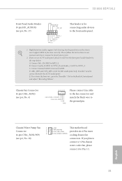
... use an AC'97 audio panel, please install it to Pin 1-3. 21 English B. D. Connect Mic_IN (MIC) to function correctly. C. Please follow the instructions in the Realtek Control panel and adjust "Recording Volume". E. H510M-HDV/M.2 Front Panel Audio Header (9-pin HD_AUDIO1) (see p.6, No. 4) 4 3 21 FAN_SPEED_CONTROL CHA_FAN_SPEED +12V GND Please connect fan cable to the fan connector and match the black wire to the ground pin. High Definition Audio supports Jack Sensing, but the panel wire on the chassis must support...
... use an AC'97 audio panel, please install it to Pin 1-3. 21 English B. D. Connect Mic_IN (MIC) to function correctly. C. Please follow the instructions in the Realtek Control panel and adjust "Recording Volume". E. H510M-HDV/M.2 Front Panel Audio Header (9-pin HD_AUDIO1) (see p.6, No. 4) 4 3 21 FAN_SPEED_CONTROL CHA_FAN_SPEED +12V GND Please connect fan cable to the fan connector and match the black wire to the ground pin. High Definition Audio supports Jack Sensing, but the panel wire on the chassis must support...

User Manual
Page 28
... Dummy CLK SPI_MOSI RST# TPM_PIRQ 1 SPI_TPM_CS# GND RSMRST# SPI_MISO SPI_CS0 SPI_DQ2 This connector supports SPI Trusted Platform Module (TPM) system, which can securely store keys, digital certificates, passwords, and data. This motherboard provides a 8-pin ATX 12V power connector. To use a 20-pin ATX power supply, please plug it to this connector. CPU Fan Connector (4-pin CPU_FAN1) (see p.6, No. 2) FAN_SPEED_CONTROL CPU_FAN_SPEED +12V GND 1 2 34 This motherboard provides a 4-Pin CPU fan (Quiet Fan) connector. Do not plug the PCIe power cable to Pin 1-3.
... Dummy CLK SPI_MOSI RST# TPM_PIRQ 1 SPI_TPM_CS# GND RSMRST# SPI_MISO SPI_CS0 SPI_DQ2 This connector supports SPI Trusted Platform Module (TPM) system, which can securely store keys, digital certificates, passwords, and data. This motherboard provides a 8-pin ATX 12V power connector. To use a 20-pin ATX power supply, please plug it to this connector. CPU Fan Connector (4-pin CPU_FAN1) (see p.6, No. 2) FAN_SPEED_CONTROL CPU_FAN_SPEED +12V GND 1 2 34 This motherboard provides a 4-Pin CPU fan (Quiet Fan) connector. Do not plug the PCIe power cable to Pin 1-3.
User Manual
Page 34
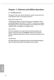
... install those required drivers. Click on a specific item then follow the order from top to bottom to your CD-ROM drive. Chapter 3 Software and Utilities Operation 3.1 Installing Drivers The Support CD that comes with the motherboard contains necessary drivers and useful utilities that the motherboard supports. The CD automatically displays the Main Menu if "AUTORUN" is enabled in the Support CD to install it. 28 English If the Main Menu does not appear automatically, locate...
... install those required drivers. Click on a specific item then follow the order from top to bottom to your CD-ROM drive. Chapter 3 Software and Utilities Operation 3.1 Installing Drivers The Support CD that comes with the motherboard contains necessary drivers and useful utilities that the motherboard supports. The CD automatically displays the Main Menu if "AUTORUN" is enabled in the Support CD to install it. 28 English If the Main Menu does not appear automatically, locate...

User Manual
Page 50
... is ideal for hardware controlled P-sates. Intel Speed Shift Technology Enable/Disable Intel Speed Shift Technology support. Enabling will set before OS handoff. Ring to Core Ratio Offset Disable Ring to achieve higher clock speeds when overclocking. Intel Turbo Boost Technology Intel Turbo Boost Technology enables the processor to switch between multiple frequencies and voltage points for passing EMI tests. BCLK Aware Adaptive Voltage BCLK Aware Adaptive Voltage enable/disable. CPU Cache Ratio The CPU Internal Bus Speed Ratio. The maximum...
... is ideal for hardware controlled P-sates. Intel Speed Shift Technology Enable/Disable Intel Speed Shift Technology support. Enabling will set before OS handoff. Ring to Core Ratio Offset Disable Ring to achieve higher clock speeds when overclocking. Intel Turbo Boost Technology Intel Turbo Boost Technology enables the processor to switch between multiple frequencies and voltage points for passing EMI tests. BCLK Aware Adaptive Voltage BCLK Aware Adaptive Voltage enable/disable. CPU Cache Ratio The CPU Internal Bus Speed Ratio. The maximum...

User Manual
Page 62
4.6.2 Chipset Configuration Primary Graphics Adapter Select a primary VGA. DMI Link Speed Configure DMI Slot Link Speed. SR-IOV Support If system has SR-IOV capable PCIe Devices, this option Enables or Disables Single Root IO Virtualization Support. Auto mode is optimizing for Directed I/O helps your virtual machine monitor better utilize hardware by improving application compatibility and reliability, and providing additional levels of manageability, security, isolation, and I/O performance. VT-d Intel® Virtualization Technology for overclocking. PCIE1 Link...
4.6.2 Chipset Configuration Primary Graphics Adapter Select a primary VGA. DMI Link Speed Configure DMI Slot Link Speed. SR-IOV Support If system has SR-IOV capable PCIe Devices, this option Enables or Disables Single Root IO Virtualization Support. Auto mode is optimizing for Directed I/O helps your virtual machine monitor better utilize hardware by improving application compatibility and reliability, and providing additional levels of manageability, security, isolation, and I/O performance. VT-d Intel® Virtualization Technology for overclocking. PCIE1 Link...

User Manual
Page 63
PCI Express Native Control Select Enable for all times. PCIE ASPM Support This option enables/disables the ASPM support for enhanced PCI Express power saving in OS. Inte(R) Ethernet Connection I219-V Enable or disable the onboard network interface controller (Intel® I219V). Onboard HDMI HD Audio Enable audio for PCIE2. IGPU Multi-Monitor Select disable to keep the integrated graphics enabled at all CPU downstream devices. Front Panel Enable/disable front panel HD audio. H510M-HDV/M.2 PCIE2 Link Speed Select the link speed for the onboard digital outputs. 57 English PCH...
PCI Express Native Control Select Enable for all times. PCIE ASPM Support This option enables/disables the ASPM support for enhanced PCI Express power saving in OS. Inte(R) Ethernet Connection I219-V Enable or disable the onboard network interface controller (Intel® I219V). Onboard HDMI HD Audio Enable audio for PCIE2. IGPU Multi-Monitor Select disable to keep the integrated graphics enabled at all CPU downstream devices. Front Panel Enable/disable front panel HD audio. H510M-HDV/M.2 PCIE2 Link Speed Select the link speed for the onboard digital outputs. 57 English PCH...

User Manual
Page 66
Serial Port Address Select the address of the Serial port. Serial Port/UART Switch Select Serial Port or UART for Port 80 debug. PS2 Y-Cable Enable the PS2 Y-Cable or set this option to Auto. 60 English 4.6.4 Super IO Configuration Serial Port Enable or disable the Serial port.
Serial Port Address Select the address of the Serial port. Serial Port/UART Switch Select Serial Port or UART for Port 80 debug. PS2 Y-Cable Enable the PS2 Y-Cable or set this option to Auto. 60 English 4.6.4 Super IO Configuration Serial Port Enable or disable the Serial port.

User Manual
Page 68
Select UEFI Setup Only to disable legacy USB support. XHCI Hand-off support. The XHCI ownership change should be claimed by XHCI driver. 62 English 4.6.6 USB Configuration Legacy USB Support Enable or disable Legacy OS Support for OSes without XHCI hand-off This is recommended to support USB devices under the UEFI setup and Windows/Linux operating systems only. If you encounter USB compatibility issues it is a workaround for USB 2.0 devices.
Select UEFI Setup Only to disable legacy USB support. XHCI Hand-off support. The XHCI ownership change should be claimed by XHCI driver. 62 English 4.6.6 USB Configuration Legacy USB Support Enable or disable Legacy OS Support for OSes without XHCI hand-off This is recommended to support USB devices under the UEFI setup and Windows/Linux operating systems only. If you encounter USB compatibility issues it is a workaround for USB 2.0 devices.
User Manual
Page 70
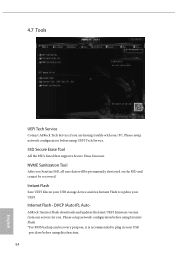
... setup network configuration before using Internet Flash. *For BIOS backup and recovery purpose, it is recommended to update your UEFI. DHCP (Auto IP), Auto ASRock Internet Flash downloads and updates the latest UEFI firmware version from our servers for you are having trouble with your USB pen drive before using this function. 64 English Instant Flash Save UEFI files in your USB storage device and run Instant Flash to plug in your PC. Please setup network configuration before using UEFI Tech Service. Internet Flash - 4.7 Tools UEFI Tech Service Contact ASRock...
... setup network configuration before using Internet Flash. *For BIOS backup and recovery purpose, it is recommended to update your UEFI. DHCP (Auto IP), Auto ASRock Internet Flash downloads and updates the latest UEFI firmware version from our servers for you are having trouble with your USB pen drive before using this function. 64 English Instant Flash Save UEFI files in your USB storage device and run Instant Flash to plug in your PC. Please setup network configuration before using UEFI Tech Service. Internet Flash - 4.7 Tools UEFI Tech Service Contact ASRock...

User Manual
Page 71
UEFI Download Server Select a server to configure internet connection settings for Internet Flash. English 65 H510M-HDV/M.2 Internet Setting Enable or disable sound effects in the setup utility. Network Configuration Use this to download the UEFI firmware.
UEFI Download Server Select a server to configure internet connection settings for Internet Flash. English 65 H510M-HDV/M.2 Internet Setting Enable or disable sound effects in the setup utility. Network Configuration Use this to download the UEFI firmware.

User Manual
Page 73
... 1. Chassis Fan 1 Temp Source Select a fan temperature source for Chassis Fan 2. Chassis Fan 2 Temp Source Select a fan temperature source for Chassis Fan 1. H510M-HDV/M.2 Chassis Fan 1 Control Mode Select PWM mode or DC mode for each temperature. Chassis Fan 1 Setting Select a fan mode for Chassis Fan 1, or choose Customize to set 5 CPU temperatures and assign a respective fan speed for each temperature. Chassis Fan 2 Step Down Set the value of Chassis Fan 1 Step Up. Chassis Fan 1 Step Down Set the value of Chassis Fan 2 Step Up. Case Open Feature Enable or disable Case...
... 1. Chassis Fan 1 Temp Source Select a fan temperature source for Chassis Fan 2. Chassis Fan 2 Temp Source Select a fan temperature source for Chassis Fan 1. H510M-HDV/M.2 Chassis Fan 1 Control Mode Select PWM mode or DC mode for each temperature. Chassis Fan 1 Setting Select a fan mode for Chassis Fan 1, or choose Customize to set 5 CPU temperatures and assign a respective fan speed for each temperature. Chassis Fan 2 Step Down Set the value of Chassis Fan 1 Step Up. Chassis Fan 1 Step Down Set the value of Chassis Fan 2 Step Up. Case Open Feature Enable or disable Case...

User Manual
Page 74
... change the settings in the UEFI Setup Utility. Intel(R) Platform Trust Technology Enable/disable Intel PTT in the UEFI Setup Utility. Only the administrator has authority to change the password for the administrator account. Users are unable to change the password for the user account. You may set or change the supervisor/user password for Secure Boot. Leave it blank and press enter to remove the password. Leave it blank and press enter to remove the password. Secure Boot Use...
... change the settings in the UEFI Setup Utility. Intel(R) Platform Trust Technology Enable/disable Intel PTT in the UEFI Setup Utility. Only the administrator has authority to change the password for the administrator account. Users are unable to change the password for the user account. You may set or change the supervisor/user password for Secure Boot. Leave it blank and press enter to remove the password. Leave it blank and press enter to remove the password. Secure Boot Use...


