User Manual
Page 4
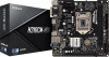
... Contents 1 1.2 Specifications 2 1.3 Motherboard Layout 6 1.4 I/O Panel 8 Chapter 2 Installation 10 2.1 Installing the CPU 11 2.2 Installing the CPU Fan and Heatsink 14 2.3 Installing Memory Modules (DIMM) 15 2.4 Expansion Slots (PCI Express Slots) 17 2.5 Onboard Headers and Connectors 18 Chapter 3 Software and Utilities Operation 22 3.1 Installing Drivers 22 3.2 A-Tuning 23 3.3 ASRock Live Update & APP Shop 26 3.3.1 UI Overview 26 3.3.2 Apps 27 3.3.3 BIOS & Drivers 30 3.3.4 Setting 31 Chapter 4 UEFI SETUP UTILITY 32 4.1 Introduction 32 4.2 EZ Mode 33
... Contents 1 1.2 Specifications 2 1.3 Motherboard Layout 6 1.4 I/O Panel 8 Chapter 2 Installation 10 2.1 Installing the CPU 11 2.2 Installing the CPU Fan and Heatsink 14 2.3 Installing Memory Modules (DIMM) 15 2.4 Expansion Slots (PCI Express Slots) 17 2.5 Onboard Headers and Connectors 18 Chapter 3 Software and Utilities Operation 22 3.1 Installing Drivers 22 3.2 A-Tuning 23 3.3 ASRock Live Update & APP Shop 26 3.3.1 UI Overview 26 3.3.2 Apps 27 3.3.3 BIOS & Drivers 30 3.3.4 Setting 31 Chapter 4 UEFI SETUP UTILITY 32 4.1 Introduction 32 4.2 EZ Mode 33
User Manual
Page 6
... VGA cards and CPU support list on ASRock's website without notice. If you require technical support related to quality and endurance. ASRock website http://www.asrock.com. 1.1 Package Contents • ASRock H310CM-HDV / H310CM-DVS Motherboard (Micro ATX Form Factor) • ASRock H310CM-HDV / H310CM-DVS Quick Installation Guide • ASRock H310CM-HDV / H310CM-DVS Support CD • 1 x I/O Panel Shield • 2 x Serial ATA (SATA) Data Cables (Optional) 1 English In this motherboard, please visit our website for specific information about the model you for purchasing ASRock...
... VGA cards and CPU support list on ASRock's website without notice. If you require technical support related to quality and endurance. ASRock website http://www.asrock.com. 1.1 Package Contents • ASRock H310CM-HDV / H310CM-DVS Motherboard (Micro ATX Form Factor) • ASRock H310CM-HDV / H310CM-DVS Quick Installation Guide • ASRock H310CM-HDV / H310CM-DVS Support CD • 1 x I/O Panel Shield • 2 x Serial ATA (SATA) Data Cables (Optional) 1 English In this motherboard, please visit our website for specific information about the model you for purchasing ASRock...
User Manual
Page 8
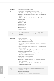
... HDMI Ports • Supports 4K Ultra HD (UHD) playback with HDMI Port H310CM-DVS: • Dual graphics output: Support DVI-D and D-Sub ports by independent display controllers • Supports DVI-D with max. resolution up to use an HD front panel audio module and enable the multi-channel audio feature through the audio driver. • Supports Surge Protection • ELNA Audio Caps • PCIE x1 Gigabit LAN 10/100/1000 Mb/s • 1 x Realtek RTL8111H • Supports Wake-On-LAN • Supports...
... HDMI Ports • Supports 4K Ultra HD (UHD) playback with HDMI Port H310CM-DVS: • Dual graphics output: Support DVI-D and D-Sub ports by independent display controllers • Supports DVI-D with max. resolution up to use an HD front panel audio module and enable the multi-channel audio feature through the audio driver. • Supports Surge Protection • ELNA Audio Caps • PCIE x1 Gigabit LAN 10/100/1000 Mb/s • 1 x Realtek RTL8111H • Supports Wake-On-LAN • Supports...
User Manual
Page 9
... RJ-45 LAN Port with LED (ACT/LINK LED and SPEED LED) • HD Audio Jacks: Line in / Front Speaker / Microphone H310CM-HDV: • 1 x D-Sub Port • 1 x DVI-D Port • 1 x HDMI Port H310CM-DVS: • 1 x D-Sub Port • 1 x DVI-D Port Storage • 4 x SATA3 6.0 Gb/s Connectors, support NCQ, AHCI and Hot Plug Connector • 1 x TPM Header • 1 x Chassis Intrusion and Speaker Header • 1 x CPU Fan Connector (4-pin) * The CPU Fan Connector supports the CPU fan of maximum 1A (12W) fan power. • 1 x Chassis/Water Pump Fan Connector (4-pin) (Smart Fan Speed...
... RJ-45 LAN Port with LED (ACT/LINK LED and SPEED LED) • HD Audio Jacks: Line in / Front Speaker / Microphone H310CM-HDV: • 1 x D-Sub Port • 1 x DVI-D Port • 1 x HDMI Port H310CM-DVS: • 1 x D-Sub Port • 1 x DVI-D Port Storage • 4 x SATA3 6.0 Gb/s Connectors, support NCQ, AHCI and Hot Plug Connector • 1 x TPM Header • 1 x Chassis Intrusion and Speaker Header • 1 x CPU Fan Connector (4-pin) * The CPU Fan Connector supports the CPU fan of maximum 1A (12W) fan power. • 1 x Chassis/Water Pump Fan Connector (4-pin) (Smart Fan Speed...
User Manual
Page 10
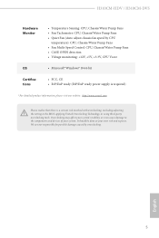
... product information, please visit our website: http://www.asrock.com Please realize that there is a certain risk involved with overclocking, including adjusting the setting in the BIOS, applying Untied Overclocking Technology, or using third-party overclocking tools. It should be done at your system. H310CM-HDV / H310CM-DVS Hardware Monitor • Temperature Sensing: CPU, Chassis/Water Pump Fans • Fan Tachometer: CPU, Chassis/Water Pump Fans • Quiet Fan (Auto adjust chassis fan speed by overclocking.
... product information, please visit our website: http://www.asrock.com Please realize that there is a certain risk involved with overclocking, including adjusting the setting in the BIOS, applying Untied Overclocking Technology, or using third-party overclocking tools. It should be done at your system. H310CM-HDV / H310CM-DVS Hardware Monitor • Temperature Sensing: CPU, Chassis/Water Pump Fans • Fan Tachometer: CPU, Chassis/Water Pump Fans • Quiet Fan (Auto adjust chassis fan speed by overclocking.
User Manual
Page 13
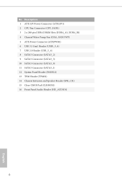
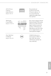
No. Description 1 ATX 12V Power Connector (ATX12V1) 2 CPU Fan Connector (CPU_FAN1) 3 2 x 288-pin DDR4 DIMM Slots (DDR4_A1, DDR4_B1) 4 Chassis/Water Pump Fan (CHA_FAN1/WP) 5 ATX Power Connector (ATXPWR1) 6 USB 3.1 Gen1 Header (USB3_3_4) 7 USB 2.0 Header (USB_5_6) 8 SATA3 Connector (SATA3_2) 9 SATA3 Connector (SATA3_3) 10 SATA3 Connector (SATA3_0) 11 SATA3 Connector (SATA3_1) 12 System Panel Header (PANEL1) 13 TPM Header (TPMS1) 14 Chassis Intrusion and Speaker Header (SPK_CI1) 15 Clear CMOS Pad (CLRMOS1) 16 Front Panel Audio Header (HD_AUDIO1) 8 English
No. Description 1 ATX 12V Power Connector (ATX12V1) 2 CPU Fan Connector (CPU_FAN1) 3 2 x 288-pin DDR4 DIMM Slots (DDR4_A1, DDR4_B1) 4 Chassis/Water Pump Fan (CHA_FAN1/WP) 5 ATX Power Connector (ATXPWR1) 6 USB 3.1 Gen1 Header (USB3_3_4) 7 USB 2.0 Header (USB_5_6) 8 SATA3 Connector (SATA3_2) 9 SATA3 Connector (SATA3_3) 10 SATA3 Connector (SATA3_0) 11 SATA3 Connector (SATA3_1) 12 System Panel Header (PANEL1) 13 TPM Header (TPMS1) 14 Chassis Intrusion and Speaker Header (SPK_CI1) 15 Clear CMOS Pad (CLRMOS1) 16 Front Panel Audio Header (HD_AUDIO1) 8 English
User Manual
Page 22
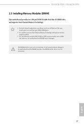
... slot; It is unable to activate Dual Channel Memory Technology with only one correct orientation. otherwise, this motherboard and DIMM may be damaged. It is not allowed to install identical (the same brand, speed, size and chip-type) DDR4 DIMM pairs. 2. The DIMM only fits in one memory module installed. 3. H310CM-HDV / H310CM-DVS 2.3 Installing Memory Modules (DIMM) This motherboard provides two 288-pin DDR4 (Double Data Rate 4) DIMM slots, and supports Dual Channel Memory Technology...
... slot; It is unable to activate Dual Channel Memory Technology with only one correct orientation. otherwise, this motherboard and DIMM may be damaged. It is not allowed to install identical (the same brand, speed, size and chip-type) DDR4 DIMM pairs. 2. The DIMM only fits in one memory module installed. 3. H310CM-HDV / H310CM-DVS 2.3 Installing Memory Modules (DIMM) This motherboard provides two 288-pin DDR4 (Double Data Rate 4) DIMM slots, and supports Dual Channel Memory Technology...
User Manual
Page 24
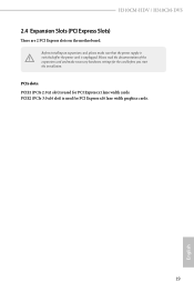
H310CM-HDV / H310CM-DVS 2.4 Expansion Slots (PCI Express Slots) There are 2 PCI Express slots on the motherboard. Before installing an expansion card, please make necessary hardware settings for PCI Express x1 lane width cards. Please read the documentation of the expansion card and make sure that the power supply is switched off or the power cord is used for PCI Express x16 lane width graphics cards. 19 English PCIE2 (PCIe 3.0 x16 slot) is used for the card before you start the installation. PCIe slots: PCIE1 (PCIe 2.0 x1 slot) is unplugged.
H310CM-HDV / H310CM-DVS 2.4 Expansion Slots (PCI Express Slots) There are 2 PCI Express slots on the motherboard. Before installing an expansion card, please make necessary hardware settings for PCI Express x1 lane width cards. Please read the documentation of the expansion card and make sure that the power supply is switched off or the power cord is used for PCI Express x16 lane width graphics cards. 19 English PCIE2 (PCIe 3.0 x16 slot) is used for the card before you start the installation. PCIe slots: PCIE1 (PCIe 2.0 x1 slot) is unplugged.
User Manual
Page 25
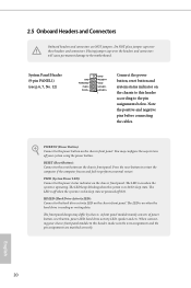
... panel module mainly consists of power button, reset button, power LED, hard drive activity LED, speaker and etc. Press the reset button to restart the computer if the computer freezes and fails to the power status indicator on the chassis front panel. English 20 2.5 Onboard Headers and Connectors Onboard headers and connectors are matched correctly. Placing jumper caps over these headers and connectors. The front panel design may configure the way to the pin assignments below. RESET (Reset Button): Connect to the hard drive activity LED...
... panel module mainly consists of power button, reset button, power LED, hard drive activity LED, speaker and etc. Press the reset button to restart the computer if the computer freezes and fails to the power status indicator on the chassis front panel. English 20 2.5 Onboard Headers and Connectors Onboard headers and connectors are matched correctly. Placing jumper caps over these headers and connectors. The front panel design may configure the way to the pin assignments below. RESET (Reset Button): Connect to the hard drive activity LED...
User Manual
Page 26
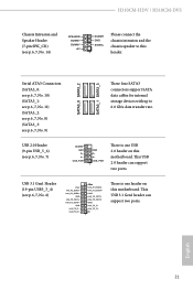
...USB 3.1 Gen1 header can support two ports. This USB 2.0 header can support two ports. USB 3.1 Gen1 Header (19-pin USB3_3_4) (see p.6, 7, No. 6) Vbus IntA_P2_SSRXIntA_P2_SSRX+ GND IntA_P2_SSTXIntA_P2_SSTX+ GND IntA_P2_DIntA_P2_D+ Vbus IntA_P3_SSRXIntA_P3_SSRX+ GND IntA_P3_SSTXIntA_P3_SSTX+ GND IntA_P3_DIntA_P3_D+ ID 1 There is one header on this motherboard. USB 2.0 Header (9-pin USB_5_6) (see p.6, 7, No. 9) SATA3_0 SATA3_2 SATA3_1 SATA3_3 These four SATA3 connectors support SATA data cables for internal storage devices with up to this motherboard. Serial ATA3 Connectors...
...USB 3.1 Gen1 header can support two ports. This USB 2.0 header can support two ports. USB 3.1 Gen1 Header (19-pin USB3_3_4) (see p.6, 7, No. 6) Vbus IntA_P2_SSRXIntA_P2_SSRX+ GND IntA_P2_SSTXIntA_P2_SSTX+ GND IntA_P2_DIntA_P2_D+ Vbus IntA_P3_SSRXIntA_P3_SSRX+ GND IntA_P3_SSTXIntA_P3_SSTX+ GND IntA_P3_DIntA_P3_D+ ID 1 There is one header on this motherboard. USB 2.0 Header (9-pin USB_5_6) (see p.6, 7, No. 9) SATA3_0 SATA3_2 SATA3_1 SATA3_3 These four SATA3 connectors support SATA data cables for internal storage devices with up to this motherboard. Serial ATA3 Connectors...
User Manual
Page 27
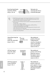
... panel wire on the chassis must support HDA to connect them for the AC'97 audio panel. Connect Mic_IN (MIC) to Ground (GND). Connect Ground (GND) to MIC2_L. Chassis/Water Pump Fan Connector (4-pin CHA_FAN1/WP) (see p.6, 7, No. 5) 12 24 1 13 22 This motherboard provides a 24-pin ATX power connector. MIC2_L 1 1. If you use a 20-pin ATX power supply, please plug it to the front audio panel. CPU Fan Connector (4-pin CPU_FAN1) (see p.6, 7, No. 16) MIC_RED PRESENCE# GND OUT2_L This header...
... panel wire on the chassis must support HDA to connect them for the AC'97 audio panel. Connect Mic_IN (MIC) to Ground (GND). Connect Ground (GND) to MIC2_L. Chassis/Water Pump Fan Connector (4-pin CHA_FAN1/WP) (see p.6, 7, No. 5) 12 24 1 13 22 This motherboard provides a 24-pin ATX power connector. MIC2_L 1 1. If you use a 20-pin ATX power supply, please plug it to the front audio panel. CPU Fan Connector (4-pin CPU_FAN1) (see p.6, 7, No. 16) MIC_RED PRESENCE# GND OUT2_L This header...
User Manual
Page 28
... store keys, digital certificates, passwords, and data. To clear CMOS, take out the CMOS battery and short the Clear CMOS Pad. ATX 12V Power Connector (8-pin ATX12V1) (see p.6, 7, No. 1) TPM Header (17-pin TPMS1) (see p.6, 7, No. 13) Clear CMOS Pad (CLRMOS1) (see p.6, 7, No. 15) GND SERIRQ # S_PWRDWN # GN D LAD1 LAD2 SMB_DATA_MAIN SMB_CLK_MAIN GN D +3VS B LAD0 +3V LAD3 PCIRST # FRAM E PCICLK H310CM-HDV / H310CM-DVS 8 5 This motherboard provides an 8-pin ATX 4 1 12V power connector. To use a 4-pin ATX power supply, please plug...
... store keys, digital certificates, passwords, and data. To clear CMOS, take out the CMOS battery and short the Clear CMOS Pad. ATX 12V Power Connector (8-pin ATX12V1) (see p.6, 7, No. 1) TPM Header (17-pin TPMS1) (see p.6, 7, No. 13) Clear CMOS Pad (CLRMOS1) (see p.6, 7, No. 15) GND SERIRQ # S_PWRDWN # GN D LAD1 LAD2 SMB_DATA_MAIN SMB_CLK_MAIN GN D +3VS B LAD0 +3V LAD3 PCIRST # FRAM E PCICLK H310CM-HDV / H310CM-DVS 8 5 This motherboard provides an 8-pin ATX 4 1 12V power connector. To use a 4-pin ATX power supply, please plug...
User Manual
Page 29
Therefore, the drivers you install can work properly. Click on a specific item then follow the order from top to bottom to your system will be auto-detected and listed on the file "ASRSETUP.EXE" in your CD-ROM drive. The CD automatically displays the Main Menu if "AUTORUN" is enabled in the Support CD to install it. 24 English If the Main Menu does not appear automatically, locate and...
Therefore, the drivers you install can work properly. Click on a specific item then follow the order from top to bottom to your system will be auto-detected and listed on the file "ASRSETUP.EXE" in your CD-ROM drive. The CD automatically displays the Main Menu if "AUTORUN" is enabled in the Support CD to install it. 24 English If the Main Menu does not appear automatically, locate and...
User Manual
Page 54
Enable for power saving. H310CM-HDV / H310CM-DVS Package C State Support Enable CPU, PCIe, Memory, Graphics C State Support for better performance. Intel Virtualization Technology Intel Virtualization Technology allows a platform to keep the CPU from overheating. Enable for the processor. Adjacent Cache Line Prefetch Automatically prefetch the subsequent cache line while retrieving the currently requested cache line. Software Guard Extensions (SGX) Use this item to disable or enable the CFG Lock. CFG Lock This item...
Enable for power saving. H310CM-HDV / H310CM-DVS Package C State Support Enable CPU, PCIe, Memory, Graphics C State Support for better performance. Intel Virtualization Technology Intel Virtualization Technology allows a platform to keep the CPU from overheating. Enable for the processor. Adjacent Cache Line Prefetch Automatically prefetch the subsequent cache line while retrieving the currently requested cache line. Software Guard Extensions (SGX) Use this item to disable or enable the CFG Lock. CFG Lock This item...
User Manual
Page 55
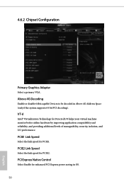
... virtual machine monitor better utilize hardware by improving application compatibility and reliability, and providing additional levels of manageability, security, isolation, and I/O performance. VT-d Intel® Virtualization Technology for PCIE2. PCIE1 Link Speed Select the link speed for enhanced PCI Express power saving in Above 4G Address Space (only if the system supports 64 bit PCI decoding). 4.6.2 Chipset Configuration Primary Graphics Adapter Select a primary VGA. Above 4G Decoding Enable or disable...
... virtual machine monitor better utilize hardware by improving application compatibility and reliability, and providing additional levels of manageability, security, isolation, and I/O performance. VT-d Intel® Virtualization Technology for PCIE2. PCIE1 Link Speed Select the link speed for enhanced PCI Express power saving in Above 4G Address Space (only if the system supports 64 bit PCI decoding). 4.6.2 Chipset Configuration Primary Graphics Adapter Select a primary VGA. Above 4G Decoding Enable or disable...
User Manual
Page 56
... is installed. Onboard LAN Enable or disable the onboard network interface controller. Onboard HDMI HD Audio Enable audio for all times. Select enable to enable onboard HD audio and automatically disable it when a sound card is shut down. Share Memory Configure the size of the DMI Link. PCH PCIE ASPM Support This option enables/disables the ASPM support for the onboard digital outputs. IGPU Multi-Monitor Select disable to disable the integrated graphics when an external graphics card is selected, the power will start to the integrated graphics processor when...
... is installed. Onboard LAN Enable or disable the onboard network interface controller. Onboard HDMI HD Audio Enable audio for all times. Select enable to enable onboard HD audio and automatically disable it when a sound card is shut down. Share Memory Configure the size of the DMI Link. PCH PCIE ASPM Support This option enables/disables the ASPM support for the onboard digital outputs. IGPU Multi-Monitor Select disable to disable the integrated graphics when an external graphics card is selected, the power will start to the integrated graphics processor when...
User Manual
Page 60
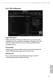
... hand-off This is recommended to support USB devices under the UEFI setup and Windows/Linux operating systems only. This should be enabled for the complete USB keyboard legacy support for USB 2.0 devices. Select UEFI Setup Only to disable legacy USB support. The XHCI ownership change should be claimed by XHCI driver. 55 English 4.6.6 USB Configuration H310CM-HDV / H310CM-DVS Legacy USB Support Enable or disable Legacy OS Support for non-USB aware OSes. XHCI Hand-off support. PS/2 Simulator Enable the support of I/O port 60h/64h emulation.
... hand-off This is recommended to support USB devices under the UEFI setup and Windows/Linux operating systems only. This should be enabled for the complete USB keyboard legacy support for USB 2.0 devices. Select UEFI Setup Only to disable legacy USB support. The XHCI ownership change should be claimed by XHCI driver. 55 English 4.6.6 USB Configuration H310CM-HDV / H310CM-DVS Legacy USB Support Enable or disable Legacy OS Support for non-USB aware OSes. XHCI Hand-off support. PS/2 Simulator Enable the support of I/O port 60h/64h emulation.
User Manual
Page 62
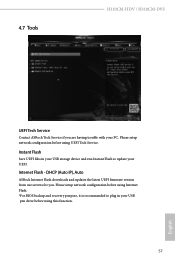
4.7 Tools H310CM-HDV / H310CM-DVS UEFI Tech Service Contact ASRock Tech Service if you . Instant Flash Save UEFI files in your USB storage device and run Instant Flash to plug in your USB pen drive before using this function. 57 English Internet Flash - Please setup network configuration before using UEFI Tech Service. DHCP (Auto IP), Auto ASRock Internet Flash downloads and updates the latest UEFI firmware version from our servers for you are having trouble with your UEFI. Please setup network configuration before using Internet Flash. *For BIOS backup and recovery purpose...
4.7 Tools H310CM-HDV / H310CM-DVS UEFI Tech Service Contact ASRock Tech Service if you . Instant Flash Save UEFI files in your USB storage device and run Instant Flash to plug in your USB pen drive before using this function. 57 English Internet Flash - Please setup network configuration before using UEFI Tech Service. DHCP (Auto IP), Auto ASRock Internet Flash downloads and updates the latest UEFI firmware version from our servers for you are having trouble with your UEFI. Please setup network configuration before using Internet Flash. *For BIOS backup and recovery purpose...
User Manual
Page 63
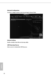
Internet Setting Enable or disable sound effects in the setup utility. UEFI Download Server Select a server to configure internet connection settings for Internet Flash. Network Configuration Use this to download the UEFI firmware. 58 English
Internet Setting Enable or disable sound effects in the setup utility. UEFI Download Server Select a server to configure internet connection settings for Internet Flash. Network Configuration Use this to download the UEFI firmware. 58 English
User Manual
Page 66
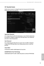
... password. H310CM-HDV / H310CM-DVS 4.9 Security Screen In this section you may also clear the user password. User Password Set or change the settings in the UEFI Setup Utility. Intel(R) Platform Trust Technology Enable/disable Intel PTT in the UEFI Setup Utility. Leave it blank and press enter to change the password for Secure Boot. Secure Boot Use this option to enable or disable support for the administrator account. Disable this item to use discrete TPM Module. 61 English You may set or change the supervisor/user password...
... password. H310CM-HDV / H310CM-DVS 4.9 Security Screen In this section you may also clear the user password. User Password Set or change the settings in the UEFI Setup Utility. Intel(R) Platform Trust Technology Enable/disable Intel PTT in the UEFI Setup Utility. Leave it blank and press enter to change the password for Secure Boot. Secure Boot Use this option to enable or disable support for the administrator account. Disable this item to use discrete TPM Module. 61 English You may set or change the supervisor/user password...


