User Manual
Page 2
... two conditions: (1) this device may not cause harmful interference, and (2) this motherboard contains Perchlorate, a toxic substance controlled in Perchlorate Best Management Practices (BMP) regulations passed by ASRock. CALIFORNIA, USA ONLY The Lithium battery adopted on this device must accept any ...any form or by any defect or error in this documentation. "Perchlorate Material-special handling may cause undesired operation. ASRock assumes no event shall ASRock, its directors, officers, employees, or agents be liable for any indirect, special, incidental, or consequential damages (...
... two conditions: (1) this device may not cause harmful interference, and (2) this motherboard contains Perchlorate, a toxic substance controlled in Perchlorate Best Management Practices (BMP) regulations passed by ASRock. CALIFORNIA, USA ONLY The Lithium battery adopted on this device must accept any ...any form or by any defect or error in this documentation. "Perchlorate Material-special handling may cause undesired operation. ASRock assumes no event shall ASRock, its directors, officers, employees, or agents be liable for any indirect, special, incidental, or consequential damages (...
User Manual
Page 4
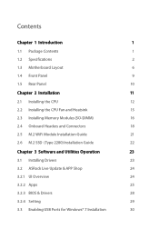
Contents Chapter 1 Introduction 1 1.1 Package Contents 1 1.2 Specifications 2 1.3 Motherboard Layout 6 1.4 Front Panel 9 1.5 Rear Panel 10 Chapter 2 Installation 11 2.1 Installing the CPU 12 2.2 Installing the CPU Fan and Heatsink 15...2.5 M.2 WiFi Module Installation Guide 21 2.6 M.2 SSD (Type 2280) Installation Guide 22 Chapter 3 Software and Utilities Operation 23 3.1 Installing Drivers 23 3.2 ASRock Live Update & APP Shop 24 3.2.1 UI Overview 24 3.2.2 Apps 25 3.2.3 BIOS & Drivers 28 3.2.4 Setting 29 3.3 Enabling USB Ports for Windows® 7 Installation...
Contents Chapter 1 Introduction 1 1.1 Package Contents 1 1.2 Specifications 2 1.3 Motherboard Layout 6 1.4 Front Panel 9 1.5 Rear Panel 10 Chapter 2 Installation 11 2.1 Installing the CPU 12 2.2 Installing the CPU Fan and Heatsink 15...2.5 M.2 WiFi Module Installation Guide 21 2.6 M.2 SSD (Type 2280) Installation Guide 22 Chapter 3 Software and Utilities Operation 23 3.1 Installing Drivers 23 3.2 ASRock Live Update & APP Shop 24 3.2.1 UI Overview 24 3.2.2 Apps 25 3.2.3 BIOS & Drivers 28 3.2.4 Setting 29 3.3 Enabling USB Ports for Windows® 7 Installation...
User Manual
Page 6
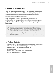
... this documentation will be subject to quality and endurance. H110M-STX / H110M-STX/COM Chapter 1 Introduction Thank you are using. Chapter 3 contains the operation guide of the BIOS setup. ASRock website http://www.asrock.com. 1.1 Package Contents • ASRock H110M-STX / H110M-STX/COM Motherboard (Mini-STX Form Factor) • ASRock H110M-STX / H110M-STX/COM Quick Installation Guide • ASRock H110M-STX / H110M-STX/COM Support CD • 1 x I/O Panel Shield • 2 x Serial...
... this documentation will be subject to quality and endurance. H110M-STX / H110M-STX/COM Chapter 1 Introduction Thank you are using. Chapter 3 contains the operation guide of the BIOS setup. ASRock website http://www.asrock.com. 1.1 Package Contents • ASRock H110M-STX / H110M-STX/COM Motherboard (Mini-STX Form Factor) • ASRock H110M-STX / H110M-STX/COM Quick Installation Guide • ASRock H110M-STX / H110M-STX/COM Support CD • 1 x I/O Panel Shield • 2 x Serial...
User Manual
Page 11
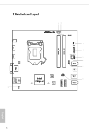
1.3 Motherboard Layout 12 DC Jack DP1 HDMI1 Audio CODEC VGA1 USB 2.0 T: USB3 Top: USB 3.0 RJ-45 B: USB4 9 1 CI1 H110M-STX CPU_FAN2 RoHS DDR4_A1 DDR4_B1 3 CPU_FAN1 1 4 LPC1 SPEAKER1 USB_5_6 1 5 1 COM1 6 1 Mic In 7 USB 3.0 USB_2 Intel Chipset M2_1_CT1 BIOS ROM M2_2_CT1 Super I/O PANEL1 PLED PWRBTN 1 HDLED RESET USB 3.0 USB_1 8 Headphone / Headset M.2 WiFi M.2 PCIe SSD English 6
1.3 Motherboard Layout 12 DC Jack DP1 HDMI1 Audio CODEC VGA1 USB 2.0 T: USB3 Top: USB 3.0 RJ-45 B: USB4 9 1 CI1 H110M-STX CPU_FAN2 RoHS DDR4_A1 DDR4_B1 3 CPU_FAN1 1 4 LPC1 SPEAKER1 USB_5_6 1 5 1 COM1 6 1 Mic In 7 USB 3.0 USB_2 Intel Chipset M2_1_CT1 BIOS ROM M2_2_CT1 Super I/O PANEL1 PLED PWRBTN 1 HDLED RESET USB 3.0 USB_1 8 Headphone / Headset M.2 WiFi M.2 PCIe SSD English 6
User Manual
Page 16
... object before you handle the components. • Hold components by the edges and do so may damage the motherboard. 11 English H110M-STX / H110M-STX/COM Chapter 2 Installation This is a Mini-STX form factor motherboard. Also remember to the motherboard's components, NEVER place your chassis to ensure that comes with the components. • When placing screws to secure...
... object before you handle the components. • Hold components by the edges and do so may damage the motherboard. 11 English H110M-STX / H110M-STX/COM Chapter 2 Installation This is a Mini-STX form factor motherboard. Also remember to the motherboard's components, NEVER place your chassis to ensure that comes with the components. • When placing screws to secure...
User Manual
Page 19
Please save and replace the cover if the processor is removed. The cover must be placed if you wish to return the motherboard for after service. 14 English
Please save and replace the cover if the processor is removed. The cover must be placed if you wish to return the motherboard for after service. 14 English
User Manual
Page 21
It is not allowed to the motherboard and the SO-DIMM if you force the SO-DIMM into a DDR4 slot; otherwise, this motherboard and SO-DIMM may be damaged. The SO-DIMM only fits in one correct orientation. 2.3 Installing Memory Modules (SO-DIMM) This motherboard provides two 260-pin DDR4 (Double Data Rate 4) SO-DIMM slots. It will cause permanent damage to install a DDR, DDR2 or DDR3 memory module into the slot at incorrect orientation. 16 English
It is not allowed to the motherboard and the SO-DIMM if you force the SO-DIMM into a DDR4 slot; otherwise, this motherboard and SO-DIMM may be damaged. The SO-DIMM only fits in one correct orientation. 2.3 Installing Memory Modules (SO-DIMM) This motherboard provides two 260-pin DDR4 (Double Data Rate 4) SO-DIMM slots. It will cause permanent damage to install a DDR, DDR2 or DDR3 memory module into the slot at incorrect orientation. 16 English
User Manual
Page 23
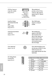
... Drive Activity LED): Connect to the pin assignments below. Press the reset switch to restart the computer if the computer freezes and fails to the motherboard. English 18 The LED is reading or writing data. RESET (Reset Switch): Connect to this header according to the hard drive activity LED on when...
... Drive Activity LED): Connect to the pin assignments below. Press the reset switch to restart the computer if the computer freezes and fails to the motherboard. English 18 The LED is reading or writing data. RESET (Reset Switch): Connect to this header according to the hard drive activity LED on when...
User Manual
Page 24
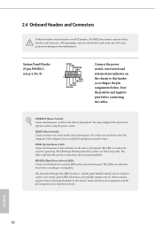
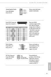
... Connector 1 (4-pin CPU_FAN1) 2 3 (see p.4, No. 6) Front_LFront_L+ Front_R+ Front_R- English 19 H110M-STX / H110M-STX/COM Internal Speaker Header 1 (4-pin SPEAKER1) (see p.4, No. 3) 4 GN D + 12V CPU_ FAN_SPEED FAN_SPEED_CONTROL This motherboard provides a 4-Pin CPU fan (Quiet Fan) connector. USB_PWR GND P+ PUSB_PWR 1 There is one header...connectors support SATA data cables for internal storage devices with up to Pin 1-3. Please connect the chassis speaker to this motherboard. If you plan to connect a 3-Pin CPU fan, please connect it to 6.0 Gb/s data transfer rate. *...
... Connector 1 (4-pin CPU_FAN1) 2 3 (see p.4, No. 6) Front_LFront_L+ Front_R+ Front_R- English 19 H110M-STX / H110M-STX/COM Internal Speaker Header 1 (4-pin SPEAKER1) (see p.4, No. 3) 4 GN D + 12V CPU_ FAN_SPEED FAN_SPEED_CONTROL This motherboard provides a 4-Pin CPU fan (Quiet Fan) connector. USB_PWR GND P+ PUSB_PWR 1 There is one header...connectors support SATA data cables for internal storage devices with up to Pin 1-3. Please connect the chassis speaker to this motherboard. If you plan to connect a 3-Pin CPU fan, please connect it to 6.0 Gb/s data transfer rate. *...
User Manual
Page 25
This feature requires a chassis with chassis intrusion detection design. Serial Port Header (for H110M-STX/COM only) (9-pin COM1) (see p.4, No. 4) This motherboard 1 supports CASE OPEN detection feature that detects if the chassis cove has been removed. PIN Signal Name PIN Signal Name 1 CLK 2 GND 3 RESET# 4 LFRAME# 5 LAD0 6 ... the data in CMOS. This connector supports Intel® 1L Thermal Modules. CPU Fan Connector (5-pin CPU_FAN2) (see p.4, No. 1) GND GND FAN_VOLTAGE FAN_SPEED FAN_SPEED_CONTROL This motherboard provides a 5-Pin CPU fan connector.
This feature requires a chassis with chassis intrusion detection design. Serial Port Header (for H110M-STX/COM only) (9-pin COM1) (see p.4, No. 4) This motherboard 1 supports CASE OPEN detection feature that detects if the chassis cove has been removed. PIN Signal Name PIN Signal Name 1 CLK 2 GND 3 RESET# 4 LFRAME# 5 LAD0 6 ... the data in CMOS. This connector supports Intel® 1L Thermal Modules. CPU Fan Connector (5-pin CPU_FAN2) (see p.4, No. 1) GND GND FAN_VOLTAGE FAN_SPEED FAN_SPEED_CONTROL This motherboard provides a 5-Pin CPU fan connector.
User Manual
Page 26
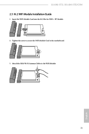
Attach the SMA Wi-Fi Antenna Cables to the motherboard. 3. Tighten the screw to secure the WiFi Module Card to the WiFi Module. 21 English H110M-STX / H110M-STX/COM 2.5 M.2 WiFi Module Installation Guide 1. Insert the WiFi Module Card into the M.2 Slot for WiFi + BT Module. 2.
Attach the SMA Wi-Fi Antenna Cables to the motherboard. 3. Tighten the screw to secure the WiFi Module Card to the WiFi Module. 21 English H110M-STX / H110M-STX/COM 2.5 M.2 WiFi Module Installation Guide 1. Insert the WiFi Module Card into the M.2 Slot for WiFi + BT Module. 2.
User Manual
Page 27
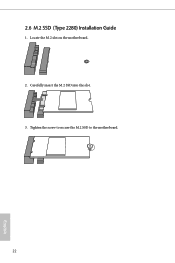
Carefully insert the M.2 SSD into the slot. 3. 2.6 M.2 SSD (Type 2280) Installation Guide 1. Locate the M.2 slot on the motherboard. 2. Tighten the screw to secure the M.2 SSD to the motherboard. 22 English
Carefully insert the M.2 SSD into the slot. 3. 2.6 M.2 SSD (Type 2280) Installation Guide 1. Locate the M.2 slot on the motherboard. 2. Tighten the screw to secure the M.2 SSD to the motherboard. 22 English
User Manual
Page 28
... English Utilities Menu The Utilities Menu shows the application software that enhance the motherboard's features. H110M-STX / H110M-STX/COM Chapter 3 Software and Utilities Operation 3.1 Installing Drivers The Support CD that comes with the motherboard contains necessary drivers and useful utilities that the motherboard supports. The CD automatically displays the Main Menu if "AUTORUN" is enabled in...
... English Utilities Menu The Utilities Menu shows the application software that enhance the motherboard's features. H110M-STX / H110M-STX/COM Chapter 3 Software and Utilities Operation 3.1 Installing Drivers The Support CD that comes with the motherboard contains necessary drivers and useful utilities that the motherboard supports. The CD automatically displays the Main Menu if "AUTORUN" is enabled in...
User Manual
Page 29
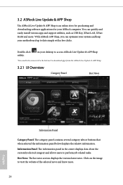
... Category Panel: The category panel contains several category tabs or buttons that when selected the information panel below displays the relative information. With ASRock APP Shop, you can quickly and easily install various apps and support utilities, such as USB Key, XFast LAN, XFast RAM and ...more . 24 English 3.2 ASRock Live Update & APP Shop The ASRock Live Update & APP Shop is an online store for purchasing and downloading software applications for your motherboard up to date simply with a few clicks. Double-click utility. on the image...
... Category Panel: The category panel contains several category tabs or buttons that when selected the information panel below displays the relative information. With ASRock APP Shop, you can quickly and easily install various apps and support utilities, such as USB Key, XFast LAN, XFast RAM and ...more . 24 English 3.2 ASRock Live Update & APP Shop The ASRock Live Update & APP Shop is an online store for purchasing and downloading software applications for your motherboard up to date simply with a few clicks. Double-click utility. on the image...
User Manual
Page 35
USB3.0). Due to that fact that XHCI is not included in the ASRock Support CD or downloaded from website) 30 English Requirements • A Windows® 7 installation disk or USB drive • A Windows® PC • Win7 USB Patcher (...; 7 Installation Intel® Braswell and Skylake has removed their support for the USB ports to install Windows 7 operating system because the USB ports on their motherboard won't work. USB2.0) and only kept the eXtensible Host Controller Interface (XHCI -
USB3.0). Due to that fact that XHCI is not included in the ASRock Support CD or downloaded from website) 30 English Requirements • A Windows® 7 installation disk or USB drive • A Windows® PC • Win7 USB Patcher (...; 7 Installation Intel® Braswell and Skylake has removed their support for the USB ports to install Windows 7 operating system because the USB ports on their motherboard won't work. USB2.0) and only kept the eXtensible Host Controller Interface (XHCI -
User Manual
Page 44
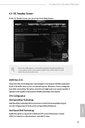
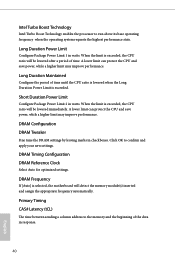
H110M-STX / H110M-STX/COM 4.5 OC Tweaker Screen In the OC Tweaker screen, you see on the quality of the memory DIMMs and system environment. Please use a better cooling solution while overclocking. It should be done at your memory DIMMs and motherboard. It depends on your system unstable. CPU Configuration Intel SpeedStep Technology Intel SpeedStep technology...
H110M-STX / H110M-STX/COM 4.5 OC Tweaker Screen In the OC Tweaker screen, you see on the quality of the memory DIMMs and system environment. Please use a better cooling solution while overclocking. It should be done at your memory DIMMs and motherboard. It depends on your system unstable. CPU Configuration Intel SpeedStep Technology Intel SpeedStep technology...
User Manual
Page 45
When the limit is selected, the motherboard will be lowered after a period of time. DRAM Timing Configuration DRAM Reference Clock Select Auto for optimized settings. DRAM Frequency If [Auto] is exceeded, the ...
When the limit is selected, the motherboard will be lowered after a period of time. DRAM Timing Configuration DRAM Reference Clock Select Auto for optimized settings. DRAM Frequency If [Auto] is exceeded, the ...
User Manual
Page 64
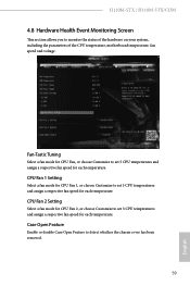
H110M-STX / H110M-STX/COM 4.8 Hardware Health Event Monitoring Screen This section allows you to detect whether the chassis cover has been removed. 59 English Fan-Tastic Tuning Select a ... Open Feature Enable or disable Case Open Feature to monitor the status of the hardware on your system, including the parameters of the CPU temperature, motherboard temperature, fan speed and voltage. CPU Fan 2 Setting Select a fan mode for CPU Fan 2, or choose Customize to set 5 CPU temperatures and assign a respective fan...
H110M-STX / H110M-STX/COM 4.8 Hardware Health Event Monitoring Screen This section allows you to detect whether the chassis cover has been removed. 59 English Fan-Tastic Tuning Select a ... Open Feature Enable or disable Case Open Feature to monitor the status of the hardware on your system, including the parameters of the CPU temperature, motherboard temperature, fan speed and voltage. CPU Fan 2 Setting Select a fan mode for CPU Fan 2, or choose Customize to set 5 CPU temperatures and assign a respective fan...

