

User Manual
Page 5
.... In case any modifications of this documentation will be updated, the content of the software and utilities. ASRock website http://www.asrock.com. 1.1 Package Contents • ASRock H110M-DGS/D3 Motherboard (Micro ATX Form Factor) • ASRock H110M-DGS/D3 Quick Installation Guide • ASRock H110M-DGS/D3 Support CD • 2 x Serial ATA (SATA) Data Cables (Optional) • 1 x I/O Panel Shield 1 English Because the motherboard...
.... In case any modifications of this documentation will be updated, the content of the software and utilities. ASRock website http://www.asrock.com. 1.1 Package Contents • ASRock H110M-DGS/D3 Motherboard (Micro ATX Form Factor) • ASRock H110M-DGS/D3 Quick Installation Guide • ASRock H110M-DGS/D3 Support CD • 2 x Serial ATA (SATA) Data Cables (Optional) • 1 x I/O Panel Shield 1 English Because the motherboard...
User Manual
Page 7
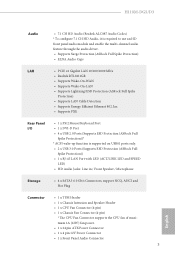
H110M-DGS/D3 Audio • 7.1 CH HD Audio (Realtek ALC887 Audio Codec) * To configure 7.1 CH HD Audio, it is required to use an HD front panel audio module and enable the multi-channel audio feature through the audio driver. • Supports Surge Protection (ASRock Full Spike Protection) ...10/100/1000 Mb/s • Realtek RTL8111GR • Supports Wake-On-WAN • Supports Wake-On-LAN • Supports Lightning/ESD Protection (ASRock Full Spike Protection) • Supports LAN Cable Detection • Supports Energy Efficient Ethernet 802.3az • Supports PXE Rear Panel I/O •...
H110M-DGS/D3 Audio • 7.1 CH HD Audio (Realtek ALC887 Audio Codec) * To configure 7.1 CH HD Audio, it is required to use an HD front panel audio module and enable the multi-channel audio feature through the audio driver. • Supports Surge Protection (ASRock Full Spike Protection) ...10/100/1000 Mb/s • Realtek RTL8111GR • Supports Wake-On-WAN • Supports Wake-On-LAN • Supports Lightning/ESD Protection (ASRock Full Spike Protection) • Supports LAN Cable Detection • Supports Energy Efficient Ethernet 802.3az • Supports PXE Rear Panel I/O •...
User Manual
Page 9
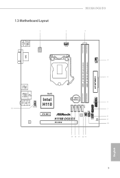
1.3 Motherboard Layout 1 2 H110M-DGS/D3 3 USB 2.0 T: USB0 B: USB1 PS2 Keyboard /Mouse ATX12V1 CPU_FAN1 4 CHA_FAN1 DVI1 DDR3_A1 (64 bit, 240-pin module) DDR3_B1 (64 bit, 240-pin module) ATXPWR1 5 USB 3.0 T: USB1 B: USB2 USB 2.0 T: USB2 B: USB3 Top: RJ-45 RoHS Intel Top: LINE IN Center: FRONT Bottom: MIC IN 1 H110 HD_AUDIO1 16 SATA3_3 SATA3_2 SATA3_1 SATA3_0 USB3_3_4 1 CMOS Battery 6 1 7 PANEL1 SPK_CI1 PLED PWRBTN HDLED RESET PCIE1 1 BIOS TPMS1 1 ROM 8 1 H110M-DGS/D3 USB4_5 9 CLRMOS1 Audio CODEC PCIE2 10 15 14 13 12 11 English 5
1.3 Motherboard Layout 1 2 H110M-DGS/D3 3 USB 2.0 T: USB0 B: USB1 PS2 Keyboard /Mouse ATX12V1 CPU_FAN1 4 CHA_FAN1 DVI1 DDR3_A1 (64 bit, 240-pin module) DDR3_B1 (64 bit, 240-pin module) ATXPWR1 5 USB 3.0 T: USB1 B: USB2 USB 2.0 T: USB2 B: USB3 Top: RJ-45 RoHS Intel Top: LINE IN Center: FRONT Bottom: MIC IN 1 H110 HD_AUDIO1 16 SATA3_3 SATA3_2 SATA3_1 SATA3_0 USB3_3_4 1 CMOS Battery 6 1 7 PANEL1 SPK_CI1 PLED PWRBTN HDLED RESET PCIE1 1 BIOS TPMS1 1 ROM 8 1 H110M-DGS/D3 USB4_5 9 CLRMOS1 Audio CODEC PCIE2 10 15 14 13 12 11 English 5
User Manual
Page 11
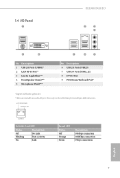
1.4 I/O Panel 1 H110M-DGS/D3 2 3 4 9 8 No. Please refer to the table below for the LAN port LED indications. ACT/LINK LED SPEED LED LAN Port Activity / Link LED Status Off ...
1.4 I/O Panel 1 H110M-DGS/D3 2 3 4 9 8 No. Please refer to the table below for the LAN port LED indications. ACT/LINK LED SPEED LED LAN Port Activity / Link LED Status Off ...

User Manual
Page 13
Also remember to do so may damage the motherboard. 9 English H110M-DGS/D3 Chapter 2 Installation This is a Micro ATX form factor motherboard. Failure to use a grounded wrist strap or touch a safety grounded object before installing or removing the ...
Also remember to do so may damage the motherboard. 9 English H110M-DGS/D3 Chapter 2 Installation This is a Micro ATX form factor motherboard. Failure to use a grounded wrist strap or touch a safety grounded object before installing or removing the ...
User Manual
Page 17
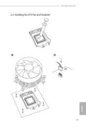
2.2 Installing the CPU Fan and Heatsink H110M-DGS/D3 1 2 CPU_FAN English 13
2.2 Installing the CPU Fan and Heatsink H110M-DGS/D3 1 2 CPU_FAN English 13

User Manual
Page 21
... caps over the headers and connectors will cause permanent damage to this header, make sure the wire assignments and the pin assignments are NOT jumpers. H110M-DGS/D3 2.5 Onboard Headers and Connectors Onboard headers and connectors are matched correctly. Placing jumper caps over these headers and connectors. RESET (Reset Switch): Connect to the...
... caps over the headers and connectors will cause permanent damage to this header, make sure the wire assignments and the pin assignments are NOT jumpers. H110M-DGS/D3 2.5 Onboard Headers and Connectors Onboard headers and connectors are matched correctly. Placing jumper caps over these headers and connectors. RESET (Reset Switch): Connect to the...
User Manual
Page 23
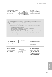
...) (see p.5, No. 16) OUT_RET MIC_RET PRESENCE# GN D This header is for OUT2_L J_SENSE connecting audio devices OUT2_R MIC2_R to the front audio panel. English 19 H110M-DGS/D3 Front Panel Audio Header (9-pin HD_AUDIO1) (see p.5, No. 4) GND FAN_VOLTAGE CHA_FAN_SPEED Please connect fan cables to the fan connector and FAN_SPEED_CONTROL match the black wire...
...) (see p.5, No. 16) OUT_RET MIC_RET PRESENCE# GN D This header is for OUT2_L J_SENSE connecting audio devices OUT2_R MIC2_R to the front audio panel. English 19 H110M-DGS/D3 Front Panel Audio Header (9-pin HD_AUDIO1) (see p.5, No. 4) GND FAN_VOLTAGE CHA_FAN_SPEED Please connect fan cables to the fan connector and FAN_SPEED_CONTROL match the black wire...

User Manual
Page 25
... click on the file "ASRSETUP.EXE" in your CD-ROM drive. Utilities Menu The Utilities Menu shows the application software that enhance the motherboard's features. H110M-DGS/D3 Chapter 3 Software and Utilities Operation 3.1 Installing Drivers The Support CD that comes with the motherboard contains necessary drivers and useful utilities that the motherboard supports.
... click on the file "ASRSETUP.EXE" in your CD-ROM drive. Utilities Menu The Utilities Menu shows the application software that enhance the motherboard's features. H110M-DGS/D3 Chapter 3 Software and Utilities Operation 3.1 Installing Drivers The Support CD that comes with the motherboard contains necessary drivers and useful utilities that the motherboard supports.

User Manual
Page 27
H110M-DGS/D3 3.2.2 Apps When the "Apps" tab is selected, you will see all the available apps on your computer. The most recommended app appears on the left ...
H110M-DGS/D3 3.2.2 Apps When the "Apps" tab is selected, you will see all the available apps on your computer. The most recommended app appears on the left ...

User Manual
Page 29
H110M-DGS/D3 Upgrading an App You can only upgrade the apps you will find the mark of "New Version" appears below the installed app icon. English 25 Step 2 Click on the app icon to start upgrading. Step 1 Click on the yellow icon to see more details. When there is an available new version for your app, you have already installed.
H110M-DGS/D3 Upgrading an App You can only upgrade the apps you will find the mark of "New Version" appears below the installed app icon. English 25 Step 2 Click on the app icon to start upgrading. Step 1 Click on the yellow icon to see more details. When there is an available new version for your app, you have already installed.

User Manual
Page 31
H110M-DGS/D3 3.2.4 Setting In the "Setting" page, you can change the language, select the server location, and determine if you want to automatically run the ASRock Live Update & APP Shop on Windows startup. 27 English
H110M-DGS/D3 3.2.4 Setting In the "Setting" page, you can change the language, select the server location, and determine if you want to automatically run the ASRock Live Update & APP Shop on Windows startup. 27 English

User Manual
Page 33
If you are using ASRock's Support CD for the USB 3.0 driver, please select your system. H110M-DGS/D3 Instructions Step 1 Insert the Windows® 7 installation disk or USB drive to your CD-ROM. 29 English Step 3 Select the "Win7 Folder" from Step1 by clicking the red circle as shown as the picture below . Step 2 Extract the tool (Win7 USB Patcher) and launch it. Step 4 Select the "USB Driver Folder" by clicking the red circle as shown as the picture below .
If you are using ASRock's Support CD for the USB 3.0 driver, please select your system. H110M-DGS/D3 Instructions Step 1 Insert the Windows® 7 installation disk or USB drive to your CD-ROM. 29 English Step 3 Select the "Win7 Folder" from Step1 by clicking the red circle as shown as the picture below . Step 2 Extract the tool (Win7 USB Patcher) and launch it. Step 4 Select the "USB Driver Folder" by clicking the red circle as shown as the picture below .

User Manual
Page 35
... SETUP UTILITY by pressing or right after POST, restart the system by pressing + + , or by turning the system off and then back on your system. H110M-DGS/D3 Chapter 4 UEFI SETUP UTILITY 4.1 Introduction This section explains how to use the UEFI SETUP UTILITY to enter the UEFI SETUP UTILITY after you see on...
... SETUP UTILITY by pressing or right after POST, restart the system by pressing + + , or by turning the system off and then back on your system. H110M-DGS/D3 Chapter 4 UEFI SETUP UTILITY 4.1 Introduction This section explains how to use the UEFI SETUP UTILITY to enter the UEFI SETUP UTILITY after you see on...
User Manual
Page 37
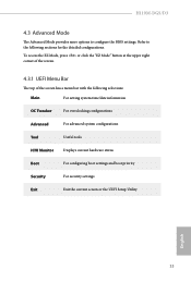
... upper right corner of the screen. 4.3.1 UEFI Menu Bar The top of the screen has a menu bar with the following sections for the detailed configurations. H110M-DGS/D3 4.3 Advanced Mode The Advanced Mode provides more options to the following selections: Main For setting system time/date information OC Tweaker For overclocking configurations Advanced...
... upper right corner of the screen. 4.3.1 UEFI Menu Bar The top of the screen has a menu bar with the following sections for the detailed configurations. H110M-DGS/D3 4.3 Advanced Mode The Advanced Mode provides more options to the following selections: Main For setting system time/date information OC Tweaker For overclocking configurations Advanced...

User Manual
Page 39
H110M-DGS/D3 4.4 Main Screen When you enter the UEFI SETUP UTILITY, the Main screen will appear and display the system overview. Favorite Display your collection of BIOS items. Press F5 to add/remove your favorite items. 35 English
H110M-DGS/D3 4.4 Main Screen When you enter the UEFI SETUP UTILITY, the Main screen will appear and display the system overview. Favorite Display your collection of BIOS items. Press F5 to add/remove your favorite items. 35 English

User Manual
Page 41
... selected, the motherboard will be lowered immediately. Short Duration Power Limit Configure Package Power Limit 2 in response. DRAM Reference Clock Select Auto for optimized settings. H110M-DGS/D3 Long Duration Maintained Configure the period of clock cycles required between a bank active command and issuing the precharge command. 37 English
... selected, the motherboard will be lowered immediately. Short Duration Power Limit Configure Package Power Limit 2 in response. DRAM Reference Clock Select Auto for optimized settings. H110M-DGS/D3 Long Duration Maintained Configure the period of clock cycles required between a bank active command and issuing the precharge command. 37 English

User Manual
Page 43
... delay. tWRWR_sg Configure between module write to write delay. tWRRD_dg Configure between module write to read to write delay. tRDWR_sg Configure between module read delay. H110M-DGS/D3 39 English tWRRD_sg Configure between module write to read to write delay. tRDWR_dr Configure between module read delay. tWRRD_dr Configure between module write to read...
... delay. tWRWR_sg Configure between module write to write delay. tWRRD_dg Configure between module write to read to write delay. tRDWR_sg Configure between module read delay. H110M-DGS/D3 39 English tWRRD_sg Configure between module write to read to write delay. tRDWR_dr Configure between module read delay. tWRRD_dr Configure between module write to read...

User Manual
Page 45
tAONPD Configure tAONPD. tRDPDEN Configure tRDPDEN. txSDLL Configure txSDLL. Fourth Timing twRPRE Configure twRPRE. OREF_RI Configure OREF_RI. twRPDEN Configure twRPDEN. H110M-DGS/D3 41 English tXPDLL Configure tXPDLL. tZQOPER Configure tZQOPER. txs_offset Configure txs_offset. tXP Configure tXP. tREFIx9 Configure tREFIx9. Write_Early_ODT Configure Write_Early_ODT. tPRPDEN Configure tPRPDEN.
tAONPD Configure tAONPD. tRDPDEN Configure tRDPDEN. txSDLL Configure txSDLL. Fourth Timing twRPRE Configure twRPRE. OREF_RI Configure OREF_RI. twRPDEN Configure twRPDEN. H110M-DGS/D3 41 English tXPDLL Configure tXPDLL. tZQOPER Configure tZQOPER. txs_offset Configure txs_offset. tXP Configure tXP. tREFIx9 Configure tREFIx9. Write_Early_ODT Configure Write_Early_ODT. tPRPDEN Configure tPRPDEN.

User Manual
Page 47
... Configuration DRAM Voltage Use this to get better memory margin. Load User Default Load previously saved user defaults. Save User UEFI Setup Profile to disk. H110M-DGS/D3 Dll Bandwidth 3 Configure the Dll Bandwidth 3. PCH +1.0 Voltage Configure the chipset voltage (1.0V). Load User UEFI Setup Profile from Disk Load previously saved user defaults...
... Configuration DRAM Voltage Use this to get better memory margin. Load User Default Load previously saved user defaults. Save User UEFI Setup Profile to disk. H110M-DGS/D3 Dll Bandwidth 3 Configure the Dll Bandwidth 3. PCH +1.0 Voltage Configure the chipset voltage (1.0V). Load User UEFI Setup Profile from Disk Load previously saved user defaults...