
User Manual
Page 3
Advanced Menu 20 2. Security Menu 23 3. Power Menu 24 4. Exit Menu 25 3 Boot Menu 25 5. Contents 1 Introduction 4 1.1 Package Contents 4 1.2 Specifications 4 1.3 Motherboard Layout (GE Pro-M 6 1.4 Motherboard Layout (GE Pro-HT 7 1.5 ASRock I/OTM (GE Pro-M / GE Pro-HT 8 2 Installation 9 2.1 Screw Holes 9 2.2 Pre-installation Precautions 9 2.3 CPU Installation 9 2.4 Installation of Heatsink and CPU fan 10 2.5 Installation of Memory Modules (DIMM 10 2.6 Expansion Slots 11 2.7 ...
Advanced Menu 20 2. Security Menu 23 3. Power Menu 24 4. Exit Menu 25 3 Boot Menu 25 5. Contents 1 Introduction 4 1.1 Package Contents 4 1.2 Specifications 4 1.3 Motherboard Layout (GE Pro-M 6 1.4 Motherboard Layout (GE Pro-HT 7 1.5 ASRock I/OTM (GE Pro-M / GE Pro-HT 8 2 Installation 9 2.1 Screw Holes 9 2.2 Pre-installation Precautions 9 2.3 CPU Installation 9 2.4 Installation of Heatsink and CPU fan 10 2.5 Installation of Memory Modules (DIMM 10 2.6 Expansion Slots 11 2.7 ...

User Manual
Page 4
... Memory: 2 slots for DDR: DIMM1 and DIMM2 (PC1600/PC2100/ PC2700), Max. 2GB 2 slots for purchasing ASRock GE Pro-M / GE Pro-HT motherboard, a reliable motherboard produced under ASRock's consistently stringent quality control. Chapter 1 Introduction Thank you for SDR: DIMM3 and DIMM4 (PC100/ PC133), Max... on page 20 offers more advanced BIOS setup information. 1.1 Package Contents ASRock GE Pro-M or GE Pro-HT motherboard (Micro ATX form factor: 9.6" x 9.6", 24.4 x 24.4 cm) ASRock GE Pro-M / GE Pro-HT Quick Installation Guide ASRock Intel-SiS Support CD 1 cable for IDE devices (1 x ATA 66...
... Memory: 2 slots for DDR: DIMM1 and DIMM2 (PC1600/PC2100/ PC2700), Max. 2GB 2 slots for purchasing ASRock GE Pro-M / GE Pro-HT motherboard, a reliable motherboard produced under ASRock's consistently stringent quality control. Chapter 1 Introduction Thank you for SDR: DIMM3 and DIMM4 (PC100/ PC133), Max... on page 20 offers more advanced BIOS setup information. 1.1 Package Contents ASRock GE Pro-M or GE Pro-HT motherboard (Micro ATX form factor: 9.6" x 9.6", 24.4 x 24.4 cm) ASRock GE Pro-M / GE Pro-HT Quick Installation Guide ASRock Intel-SiS Support CD 1 cable for IDE devices (1 x ATA 66...

User Manual
Page 5
.... Voltage monitoring: +12V, +5V, +3V, Vcore; ACPI 1.1 compliance wake up events; To improve heat dissipation, remember to protect CPU life (ASRock U-COP) (see CAUTION 4) OS: Microsoft® Windows® 98 SE / ME / 2000 / XP compliant CAUTION! 1. Please refer to perform... advanced users' reference, see CAUTION 2);Chassis temperature sensing; Please check if the CPU fan on the motherboard functions properly before you install the PC system. 3. Although GE Pro-M/GE Pro-HT offers stepless control, it is detected, the system will automatically shutdown. CPU fan tachometer; Supports ...
.... Voltage monitoring: +12V, +5V, +3V, Vcore; ACPI 1.1 compliance wake up events; To improve heat dissipation, remember to protect CPU life (ASRock U-COP) (see CAUTION 4) OS: Microsoft® Windows® 98 SE / ME / 2000 / XP compliant CAUTION! 1. Please refer to perform... advanced users' reference, see CAUTION 2);Chassis temperature sensing; Please check if the CPU fan on the motherboard functions properly before you install the PC system. 3. Although GE Pro-M/GE Pro-HT offers stepless control, it is detected, the system will automatically shutdown. CPU fan tachometer; Supports ...

User Manual
Page 6
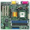
1.3 Motherboard Layout (GE Pro-M) 22 3 21 45 6 24.4cm (9.6 in) PS/2 Mouse PS/2 Keyboard CPU_FAN1 1 PS2_USB_PWR1 ATX PWR1 PARALLEL PORT PGA478B DDR DIMM1 (64/72 bit, 184-pin module) ... in LAN PHY AUX1 CD1 27 20 AUDIO1 19 AUDIO CODEC Super I/O SiS 651 Chipset Accelerated Graphics Port PCI 1 PCI 2 11 2MB PCI 3 BIOS AMR1 GE Pro-M 26 18 8 7 01 23 01 23 SiS South Bridge CMOS 9 Battery CHA_FAN1 CLRCMOS1 FLOPPY1 IR1 COM1 USB45 SPEAKER1 RESET HDLED PANEL1 PWRBTN PLED 10 14...
1.3 Motherboard Layout (GE Pro-M) 22 3 21 45 6 24.4cm (9.6 in) PS/2 Mouse PS/2 Keyboard CPU_FAN1 1 PS2_USB_PWR1 ATX PWR1 PARALLEL PORT PGA478B DDR DIMM1 (64/72 bit, 184-pin module) ... in LAN PHY AUX1 CD1 27 20 AUDIO1 19 AUDIO CODEC Super I/O SiS 651 Chipset Accelerated Graphics Port PCI 1 PCI 2 11 2MB PCI 3 BIOS AMR1 GE Pro-M 26 18 8 7 01 23 01 23 SiS South Bridge CMOS 9 Battery CHA_FAN1 CLRCMOS1 FLOPPY1 IR1 COM1 USB45 SPEAKER1 RESET HDLED PANEL1 PWRBTN PLED 10 14...

User Manual
Page 7
1.4 Motherboard Layout (GE Pro-HT) 22 3 21 45 6 24.4cm (9.6 in) PS/2 Mouse PS/2 Keyboard CPU_FAN1 1 PS2_USB_PWR1 ATX PWR1 PARALLEL PORT PGA478B DDR DIMM1 (64/72 bit, 184-pin ... in LAN PHY AUX1 CD1 27 20 19 AUDIO1 AUDIO CODEC Super I/O SiS 651HT Chipset Accelerated Graphics Port PCI 1 PCI 2 11 2MB PCI 3 BIOS AMR1 GE Pro-HT 26 18 8 7 01 23 01 23 SiS South Bridge CMOS 9 Battery CHA_FAN1 CLRCMOS1 FLOPPY1 IR1 COM1 USB45 SPEAKER1 RESET HDLED PANEL1 PWRBTN PLED 10...
1.4 Motherboard Layout (GE Pro-HT) 22 3 21 45 6 24.4cm (9.6 in) PS/2 Mouse PS/2 Keyboard CPU_FAN1 1 PS2_USB_PWR1 ATX PWR1 PARALLEL PORT PGA478B DDR DIMM1 (64/72 bit, 184-pin ... in LAN PHY AUX1 CD1 27 20 19 AUDIO1 AUDIO CODEC Super I/O SiS 651HT Chipset Accelerated Graphics Port PCI 1 PCI 2 11 2MB PCI 3 BIOS AMR1 GE Pro-HT 26 18 8 7 01 23 01 23 SiS South Bridge CMOS 9 Battery CHA_FAN1 CLRCMOS1 FLOPPY1 IR1 COM1 USB45 SPEAKER1 RESET HDLED PANEL1 PWRBTN PLED 10...
User Manual
Page 9
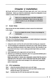
... and do so may cause physical injuries to a 90o angle. Chapter 2 Installation GE Pro-M / GE Pro-HT is detached from the wall socket before you install motherboard components or change any motherboard settings. 1. Do not over-tighten the screws! Doing so may damage the motherboard. 2.2 Pre-installation Precautions Take note of the socket lever. To avoid damaging...
... and do so may cause physical injuries to a 90o angle. Chapter 2 Installation GE Pro-M / GE Pro-HT is detached from the wall socket before you install motherboard components or change any motherboard settings. 1. Do not over-tighten the screws! Doing so may damage the motherboard. 2.2 Pre-installation Precautions Take note of the socket lever. To avoid damaging...

User Manual
Page 11
..., and AGP Slots) There are used to the chassis with screws. Remove the system unit cover (if your motherboard is already installed in place and the DIMM is used to insert ASRock MR card with the slot and press firmly until the retaining clip snap back in a chassis). Step 5. Unlock... for the card. Step 4. Step 1. Installing an expansion card Step 1. Fasten the card to install a graphics card. Step 2. Align a DIMM on both GE Pro-M and GE Pro-HT motherboards. The ASRock AGP slot has a special locking mechanism which can securely fasten the graphics card inserted.
..., and AGP Slots) There are used to the chassis with screws. Remove the system unit cover (if your motherboard is already installed in place and the DIMM is used to insert ASRock MR card with the slot and press firmly until the retaining clip snap back in a chassis). Step 5. Unlock... for the card. Step 4. Step 1. Installing an expansion card Step 1. Fasten the card to install a graphics card. Step 2. Align a DIMM on both GE Pro-M and GE Pro-HT motherboards. The ASRock AGP slot has a special locking mechanism which can securely fasten the graphics card inserted.

User Manual
Page 13
... to the secondary IDE connector (IDE2, black). Front panel audio connector (9-pin AUDIO1) (see p.6/p.7 item 13) GND P+4 P-4USB_PWR 1 USB_PWR P-5 P+5 GND DUMMY ASRock I/OTM already provided 4 default USB ports. Primary IDE connector (Blue) (39-pin IDE1) (see p.6/p.7 item 7) Secondary IDE connector (Black) (39-pin IDE2)... (see p.6/p.7 item 8) PIN1 IDE1 Blue Connect to the motherboard PIN1 IDE2 Black Connect to the IDE devices 80-Pin ATA 100/133 cable Note: To optimize compatibility and performance, please connect...
... to the secondary IDE connector (IDE2, black). Front panel audio connector (9-pin AUDIO1) (see p.6/p.7 item 13) GND P+4 P-4USB_PWR 1 USB_PWR P-5 P+5 GND DUMMY ASRock I/OTM already provided 4 default USB ports. Primary IDE connector (Blue) (39-pin IDE1) (see p.6/p.7 item 7) Secondary IDE connector (Black) (39-pin IDE2)... (see p.6/p.7 item 8) PIN1 IDE1 Blue Connect to the motherboard PIN1 IDE2 Black Connect to the IDE devices 80-Pin ATA 100/133 cable Note: To optimize compatibility and performance, please connect...

User Manual
Page 15
... you wish to enter the BIOS Setup after POST, restart the system by pressing + + , or by turning the system off and then back on the motherboard stores the BIOS Setup Utility. Because the BIOS software is constantly being updated, the following BIOS setup screens and descriptions are for you see on...
... you wish to enter the BIOS Setup after POST, restart the system by pressing + + , or by turning the system off and then back on the motherboard stores the BIOS Setup Utility. Because the BIOS software is constantly being updated, the following BIOS setup screens and descriptions are for you see on...
User Manual
Page 19
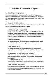
...PC system step by step. or you need to contact ASRock or want to know more information. 4.2 Support CD Information The Support CD that came with the motherboard contains necessary drivers and useful utilities that the motherboard supports. If the Main Menu did not appear automatically,...Install the necessary drivers to your OS documentation for more about ASRock, welcome to display the menus. 4.2.2 Drivers Menu The Drivers Menu shows the available devices drivers if the system detects installed devices. Because motherboard settings and hardware options vary, use the setup procedures in ...
...PC system step by step. or you need to contact ASRock or want to know more information. 4.2 Support CD Information The Support CD that came with the motherboard contains necessary drivers and useful utilities that the motherboard supports. If the Main Menu did not appear automatically,...Install the necessary drivers to your OS documentation for more about ASRock, welcome to display the menus. 4.2.2 Drivers Menu The Drivers Menu shows the available devices drivers if the system detects installed devices. Because motherboard settings and hardware options vary, use the setup procedures in ...

User Manual
Page 20
... any empty DIMM or PCI slot. You can also select other value as Microsoft® Windows® XP. Hyper-Threading Technology (for GE Pro-HT only): To enable this feature, it will be [Disabled] for this option is the multiple that includes optimization for better system stability...Microsoft® Windows® XP, or Linux kernel version 2.4.18 or higher. Whether the option is open or locked is selected, the motherboard detects the memory module(s) inserted and automatically assigns appropriate frequency. Appendix: Advanced BIOS Setup This section will equal the core speed of the ...
... any empty DIMM or PCI slot. You can also select other value as Microsoft® Windows® XP. Hyper-Threading Technology (for GE Pro-HT only): To enable this feature, it will be [Disabled] for this option is the multiple that includes optimization for better system stability...Microsoft® Windows® XP, or Linux kernel version 2.4.18 or higher. Whether the option is open or locked is selected, the motherboard detects the memory module(s) inserted and automatically assigns appropriate frequency. Appendix: Advanced BIOS Setup This section will equal the core speed of the ...

User Manual
Page 22
... options: [Disabled], [Primary], [Secondary], [Both]. OnBoard MC'97 Modem: Enable or disable onboard MC'97 modem feature. OnBoard Midi Port: Select address for CPU temperature, Motherboard temperature, CPU fan speed, and critical voltage. 22 It allows you to enable or disable the floppy drive controller. OnBoard Serial Port: Use this to...
... options: [Disabled], [Primary], [Secondary], [Both]. OnBoard MC'97 Modem: Enable or disable onboard MC'97 modem feature. OnBoard Midi Port: Select address for CPU temperature, Motherboard temperature, CPU fan speed, and critical voltage. 22 It allows you to enable or disable the floppy drive controller. OnBoard Serial Port: Use this to...

