
User Manual
Page 2
...motherboard contains Perchlorate, a toxic substance controlled in advance. Copyright Notice: No part of this manual may be liable for any indirect, special, incidental, or consequential damages (including damages for loss of profits, loss of business, loss of data, interruption of business and the like), even if ASRock... only for informational use only and subject to infringe. Disclaimer: Specifications and information contained in this manual, ASRock does not provide warranty of ASRock Inc. With respect to the contents of this manual may or may not cause harmful interference, and (2)...
...motherboard contains Perchlorate, a toxic substance controlled in advance. Copyright Notice: No part of this manual may be liable for any indirect, special, incidental, or consequential damages (including damages for loss of profits, loss of business, loss of data, interruption of business and the like), even if ASRock... only for informational use only and subject to infringe. Disclaimer: Specifications and information contained in this manual, ASRock does not provide warranty of ASRock Inc. With respect to the contents of this manual may or may not cause harmful interference, and (2)...
User Manual
Page 3
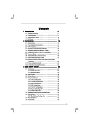
Contents 1 Introduction 5 1.1 Package Contents 5 1.2 Specifications 6 1.3 Motherboard Layout 10 1.4 I/O Panel 11 2 Installation 12 2.1 Screw Holes 12 2.2 Pre-installation Precautions 12 2.3 CPU Installation 13 2.4 Installation of Heatsink and CPU fan 15 2.5 Installation of ...
Contents 1 Introduction 5 1.1 Package Contents 5 1.2 Specifications 6 1.3 Motherboard Layout 10 1.4 I/O Panel 11 2 Installation 12 2.1 Screw Holes 12 2.2 Pre-installation Precautions 12 2.3 CPU Installation 13 2.4 Installation of Heatsink and CPU fan 15 2.5 Installation of ...
User Manual
Page 5
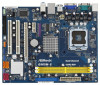
... hardware installation. You may find the latest VGA cards and CPU support lists on ASRock website without notice. www.asrock.com/support/index.asp 1.1 Package Contents ASRock G965M-S Motherboard (Micro ATX Form Factor: 9.6-in x 7.7-in, 24.4 cm x 19.6 cm) ASRock G965M-S Quick Installation Guide ASRock G965M-S Support CD One 80-conductor Ultra ATA 66/100/133 IDE Ribbon Cable...
... hardware installation. You may find the latest VGA cards and CPU support lists on ASRock website without notice. www.asrock.com/support/index.asp 1.1 Package Contents ASRock G965M-S Motherboard (Micro ATX Form Factor: 9.6-in x 7.7-in, 24.4 cm x 19.6 cm) ASRock G965M-S Quick Installation Guide ASRock G965M-S Support CD One 80-conductor Ultra ATA 66/100/133 IDE Ribbon Cable...
User Manual
Page 8
... check page 30. 3. Frequencies other words, it is not recom- Please refer to change. This motherboard supports Untied Overclocking Technology. The maximum shared memory size is defined by the chipset vendor and is a user-friendly ASRock overclocking tool which allows you to surveil your system by hardware monitor function and overclock your...
... check page 30. 3. Frequencies other words, it is not recom- Please refer to change. This motherboard supports Untied Overclocking Technology. The maximum shared memory size is defined by the chipset vendor and is a user-friendly ASRock overclocking tool which allows you to surveil your system by hardware monitor function and overclock your...

User Manual
Page 9
While CPU overheat is detected, the system will automatically shutdown. Before you install the PC system. 9 To improve heat dissipation, remember to spray thermal grease between the CPU and the heatsink when you resume the system, please check if the CPU fan on the motherboard functions properly and unplug the power cord, then plug it back again. 13.
While CPU overheat is detected, the system will automatically shutdown. Before you install the PC system. 9 To improve heat dissipation, remember to spray thermal grease between the CPU and the heatsink when you resume the system, please check if the CPU fan on the motherboard functions properly and unplug the power cord, then plug it back again. 13.
User Manual
Page 10
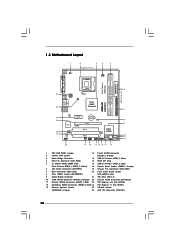
...20 Front Panel Audio Header 8 Clear CMOS Jumper (CLRCMOS1) (HD_AUDIO1, Lime) 9 South Bridge Controller 21 PCI Slots (PCI1- 2) 10 Third SATAII Connector (SATAII_3; 1.3 Motherboard Layout 1 1 PS2_USB_PWR1 2 3 4 5 19.6cm (7.7 in) CPU_FAN1 PS2 Mouse PS2 Keyboard COM1 DDRII_1 (64 bit, 240-piFnSmBod8ul0e)0 DDRII_2 (64 bit, 240-piFnSmBod8ul0e...800 VGA1 26 USB 2.0 T: USB2 B: USB3 ATX12V1 OC 800 1 USB 2.0 T: USB0 B: USB1 Top: RJ-45 25 Intel G965 Chipset G965M-S Top: Line In Center: Line Out Bottom: Mic In 24 23 22 21 LAN PHY Super IO CD1 AUDIO CODEC HD_AUDIO1 1 20 PCIE1 ...
...20 Front Panel Audio Header 8 Clear CMOS Jumper (CLRCMOS1) (HD_AUDIO1, Lime) 9 South Bridge Controller 21 PCI Slots (PCI1- 2) 10 Third SATAII Connector (SATAII_3; 1.3 Motherboard Layout 1 1 PS2_USB_PWR1 2 3 4 5 19.6cm (7.7 in) CPU_FAN1 PS2 Mouse PS2 Keyboard COM1 DDRII_1 (64 bit, 240-piFnSmBod8ul0e)0 DDRII_2 (64 bit, 240-piFnSmBod8ul0e...800 VGA1 26 USB 2.0 T: USB2 B: USB3 ATX12V1 OC 800 1 USB 2.0 T: USB0 B: USB1 Top: RJ-45 25 Intel G965 Chipset G965M-S Top: Line In Center: Line Out Bottom: Mic In 24 23 22 21 LAN PHY Super IO CD1 AUDIO CODEC HD_AUDIO1 1 20 PCIE1 ...

User Manual
Page 12
Chapter 2 Installation G965M-S is detached from the wall socket before touching any component. 2. Do not over-tighten the screws! Whenever you uninstall any component, place it . Failure to ensure that the motherboard fits into the holes indicated by the edges and do so may cause severe damage to the ...chassis. Doing so may cause physical injuries to you handle components. 3. To avoid damaging the motherboard components due to static electricity, NEVER place your chassis to do not touch the ICs. 4. Hold components by circles to secure the...
Chapter 2 Installation G965M-S is detached from the wall socket before touching any component. 2. Do not over-tighten the screws! Whenever you uninstall any component, place it . Failure to ensure that the motherboard fits into the holes indicated by the edges and do so may cause severe damage to the ...chassis. Doing so may cause physical injuries to you handle components. 3. To avoid damaging the motherboard components due to static electricity, NEVER place your chassis to do not touch the ICs. 4. Hold components by circles to secure the...

User Manual
Page 14
... thumb and peel the cap from the socket while pressing on load plate, engage the load lever. This cap must be placed if returning the motherboard for after service. Carefully place the CPU into the socket by using a purely vertical motion. Remove PnP Cap (Pick and Place Cap): Use your left...
... thumb and peel the cap from the socket while pressing on load plate, engage the load lever. This cap must be placed if returning the motherboard for after service. Carefully place the CPU into the socket by using a purely vertical motion. Remove PnP Cap (Pick and Place Cap): Use your left...

User Manual
Page 15
... cable does not interfere with fan operation or contact other . For proper installation, please kindly refer to the instruction manuals of IHS on the motherboard (CPU_FAN1, see page 10, No. 4). Rotate the fastener clockwise, then press down the fasteners without rotating them clockwise, the heatsink cannot be...of heatsink and cooling fan compliant with Intel 775-LAND CPU to dissipate heat. Please adopt the type of CPU Fan and Heatsink This motherboard is an example to illustrate the installation of the heatsink for 775-LAND CPU. Below is equipped with 775-Pin socket that the CPU...
... cable does not interfere with fan operation or contact other . For proper installation, please kindly refer to the instruction manuals of IHS on the motherboard (CPU_FAN1, see page 10, No. 4). Rotate the fastener clockwise, then press down the fasteners without rotating them clockwise, the heatsink cannot be...of heatsink and cooling fan compliant with Intel 775-LAND CPU to dissipate heat. Please adopt the type of CPU Fan and Heatsink This motherboard is an example to illustrate the installation of the heatsink for 775-LAND CPU. Below is equipped with 775-Pin socket that the CPU...

User Manual
Page 16
... is unable to activate Dual Channel Memory Technology. Firmly insert the DIMM into the slot at incorrect orientation. 2.5 Installation of Memory Modules (DIMM) G965M-S motherboard provides two 240-pin DDR2 (Double Data Rate 2) DIMM slots, and supports Dual Channel Memory Technology. Step 1. It will operate at both ends...break notch break The DIMM only fits in one memory module or two non-identical memory modules, it will cause permanent damage to the motherboard and the DIMM if you always need to install two identical (the same brand, speed, size and chip-type) memory modules in...
... is unable to activate Dual Channel Memory Technology. Firmly insert the DIMM into the slot at incorrect orientation. 2.5 Installation of Memory Modules (DIMM) G965M-S motherboard provides two 240-pin DDR2 (Double Data Rate 2) DIMM slots, and supports Dual Channel Memory Technology. Step 1. It will operate at both ends...break notch break The DIMM only fits in one memory module or two non-identical memory modules, it will cause permanent damage to the motherboard and the DIMM if you always need to install two identical (the same brand, speed, size and chip-type) memory modules in...
User Manual
Page 17
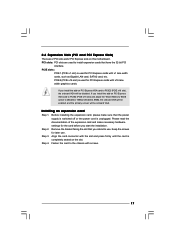
... you start the installation. PCIE2 (PCIE x16 slot) is unplugged. Step 2. Fasten the card to use . Step 4. Step 3. If you install the add-on this motherboard. Remove the bracket facing the slot that you intend to the chassis with x16 lane width graphics cards. 2.6 Expansion Slots (PCI and PCI Express Slots...
... you start the installation. PCIE2 (PCIE x16 slot) is unplugged. Step 2. Fasten the card to use . Step 4. Step 3. If you install the add-on this motherboard. Remove the bracket facing the slot that you intend to the chassis with x16 lane width graphics cards. 2.6 Expansion Slots (PCI and PCI Express Slots...
User Manual
Page 18
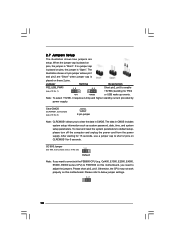
... CLRCMOS1 for PS/2 +5V +5VSB or USB wake up events. Cel400, E1000, E2000, E4000, E5000, E6000 series CPU) to short 2 pins on this motherboard. Please short pin2, pin3. Note: To select +5VSB, it requires 2 Amp and higher standby current provided by power supply. Clear CMOS (CLRCMOS1, 2-pin...system password, date, time, and system setup parameters. Otherwise, the CPU may not work properly on pins, the jumper is placed on this motherboard, you to adjust the jumpers. 2.7 Jumpers Setup The illustration shows how jumpers are "Short" when jumper cap is placed on pins, the...
... CLRCMOS1 for PS/2 +5V +5VSB or USB wake up events. Cel400, E1000, E2000, E4000, E5000, E6000 series CPU) to short 2 pins on this motherboard. Please short pin2, pin3. Note: To select +5VSB, it requires 2 Amp and higher standby current provided by power supply. Clear CMOS (CLRCMOS1, 2-pin...system password, date, time, and system setup parameters. Otherwise, the CPU may not work properly on pins, the jumper is placed on this motherboard, you to adjust the jumpers. 2.7 Jumpers Setup The illustration shows how jumpers are "Short" when jumper cap is placed on pins, the...

User Manual
Page 19
...: see p.10, No. 12) (SATAII_3: see p.10, No. 10) (SATAII_4: see p.10 No. 7) PIN1 IDE1 connect the blue end connect the black end to the motherboard to the IDE devices 80-conductor ATA 66/100/133 cable Note: Please refer to the instruction of SATA power cable to the SATA / SATAII... the white end of SATA power cable to the power connector of the SATA data cable can be connected to the power connector on the motherboard. Primary IDE connector (Blue) (39-pin IDE1, see p.10, No. 14) SATAII_3 SATAII_1 SATAII_4 SATAII_2 These Serial ATAII (SATAII) connectors support SATAII or SATA hard...
...: see p.10, No. 12) (SATAII_3: see p.10, No. 10) (SATAII_4: see p.10 No. 7) PIN1 IDE1 connect the blue end connect the black end to the motherboard to the IDE devices 80-conductor ATA 66/100/133 cable Note: Please refer to the instruction of SATA power cable to the SATA / SATAII... the white end of SATA power cable to the power connector of the SATA data cable can be connected to the power connector on the motherboard. Primary IDE connector (Blue) (39-pin IDE1, see p.10, No. 14) SATAII_3 SATAII_1 SATAII_4 SATAII_2 These Serial ATAII (SATAII) connectors support SATAII or SATA hard...
User Manual
Page 20
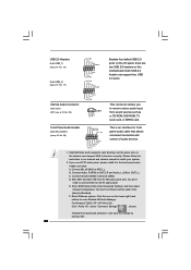
Front Panel Audio Header (9-pin HD_AUDIO1) (see p.10 No. 22) CD1 CD-L GND GND CD-R Besides four default USB 2.0 ports on this motherboard. Please follow the instruction in our manual and chassis manual to OUT2_L. D. High Definition Audio supports Jack Sensing, but the panel wire on the lower ...
Front Panel Audio Header (9-pin HD_AUDIO1) (see p.10 No. 22) CD1 CD-L GND GND CD-R Besides four default USB 2.0 ports on this motherboard. Please follow the instruction in our manual and chassis manual to OUT2_L. D. High Definition Audio supports Jack Sensing, but the panel wire on the lower ...

User Manual
Page 21
...Windows® 2000 / XP / XP 64-bit OS: Please select "Front Mic" as the default record device. Click "Set Default Device" to this motherboard provides 4-Pin CPU fan (Quiet Fan) support, the 3-Pin CPU fan still can work successfully even without the fan speed control function. GND +12V ... system front panel functions. If you want to Pin 1-3. If you plan to connect the 3-Pin CPU fan to the CPU fan connector on this motherboard, please connect it to hear your voice through front mic, please deselect "Mute" icon in the Realtek Control panel. G. For Windows® VistaTM / ...
...Windows® 2000 / XP / XP 64-bit OS: Please select "Front Mic" as the default record device. Click "Set Default Device" to this motherboard provides 4-Pin CPU fan (Quiet Fan) support, the 3-Pin CPU fan still can work successfully even without the fan speed control function. GND +12V ... system front panel functions. If you want to Pin 1-3. If you plan to connect the 3-Pin CPU fan to the CPU fan connector on this motherboard, please connect it to hear your voice through front mic, please deselect "Mute" icon in the Realtek Control panel. G. For Windows® VistaTM / ...

User Manual
Page 22
... failure to power up. 22 To use the 20-pin ATX power supply, please plug your power supply along with ATX 12V plug to this motherboard provides 24-pin ATX power connector, 12 24 it can still work if you adopt a traditional 20-pin ATX power supply. ATX Power Connector (24...
... failure to power up. 22 To use the 20-pin ATX power supply, please plug your power supply along with ATX 12V plug to this motherboard provides 24-pin ATX power connector, 12 24 it can still work if you adopt a traditional 20-pin ATX power supply. ATX Power Connector (24...
User Manual
Page 24
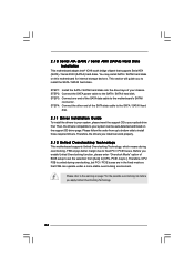
...SATA data cable to the SATA / SATAII hard disk. 2 . 1 0 Serial ATA (SATA) / Serial ATAII (SATAII) Hard Disks Installation This motherboard adopts Intel® ICH8 south bridge chipset that FSB can be auto-detected and listed on the support CD driver page. You may install SATA...setup to set the selection from up to bottom side to the warning on this motherboard for the possible overclocking risk before you install can work properly. 2 . 1 2 Untied Overclocking Technology This motherboard supports Untied Overclocking Technology, which means during overclocking, but PCI / PCIE buses ...
...SATA data cable to the SATA / SATAII hard disk. 2 . 1 0 Serial ATA (SATA) / Serial ATAII (SATAII) Hard Disks Installation This motherboard adopts Intel® ICH8 south bridge chipset that FSB can be auto-detected and listed on the support CD driver page. You may install SATA...setup to set the selection from up to bottom side to the warning on this motherboard for the possible overclocking risk before you install can work properly. 2 . 1 2 Untied Overclocking Technology This motherboard supports Untied Overclocking Technology, which means during overclocking, but PCI / PCIE buses ...

User Manual
Page 25
... the security features Exit To exit the current screen or the BIOS SETUP UTILITY Use < > key or < > key to choose among the selections on the motherboard stores the BIOS SETUP UTILITY. You may also restart by pressing the reset button on your screen. 3.1.1BIOS Menu Bar The top of the screen...
... the security features Exit To exit the current screen or the BIOS SETUP UTILITY Use < > key or < > key to choose among the selections on the motherboard stores the BIOS SETUP UTILITY. You may also restart by pressing the reset button on your screen. 3.1.1BIOS Menu Bar The top of the screen...
User Manual
Page 29
... and requires no hardware support from overheated. The C1 state is a read -only item, which displays the ratio actual value of this motherboard. NT4.0) cannot handle the function with "No Execute (NX) Memory Protection" can utilize the additional hardware capabilities provided by malicious software to... to adjust the ratio value, please disable the option " Intel (R) SpeedStep(tm) tech." in order to allow you will find this motherboard. Boot Failure Guard Enable or disable the feature of the system caches. Ratio CMOS Setting If the ratio status is "Locked" or "Unlocked...
... and requires no hardware support from overheated. The C1 state is a read -only item, which displays the ratio actual value of this motherboard. NT4.0) cannot handle the function with "No Execute (NX) Memory Protection" can utilize the additional hardware capabilities provided by malicious software to... to adjust the ratio value, please disable the option " Intel (R) SpeedStep(tm) tech." in order to allow you will find this motherboard. Boot Failure Guard Enable or disable the feature of the system caches. Ratio CMOS Setting If the ratio status is "Locked" or "Unlocked...
User Manual
Page 31
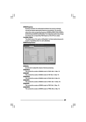
...-2005, American Megatrends, Inc. Max: 10. DRAM tRRD This controls the number of DRAM clocks for TRRD. DRAM tCL Use this option is selected, the motherboard will allow better tolerance for TRP. DRAM tRCD This controls the number of DRAM clocks for TRCD. Min: 2. Min: 3. Min: 3. DRAM tRAS This controls the...
...-2005, American Megatrends, Inc. Max: 10. DRAM tRRD This controls the number of DRAM clocks for TRRD. DRAM tCL Use this option is selected, the motherboard will allow better tolerance for TRP. DRAM tRCD This controls the number of DRAM clocks for TRCD. Min: 2. Min: 3. Min: 3. DRAM tRAS This controls the...

