User Manual
Page 3
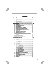
...Heatsink and CPU fan 15 2.5 Installation of Memory Modules (DIMM 16 2.6 Expansion Slots (PCI and PCI Express Slots 17 2.7 Jumpers Setup 18 2.8 Onboard Headers and Connectors 19 2.9 SATAII Hard Disk Setup Guide 23 2.10 Serial ATA (SATA) / Serial ATAII (SATAII) Hard Disks Installation 24 2.11 Driver Installation Guide 24 2.12 Untied Overclocking Technology 24 3 BIOS SETUP UTILITY 25 3.1 Introduction 25 3.1.1 BIOS Menu Bar 25 3.1.2 Navigation Keys 26 3.2 Main Screen 26 3.3 Smart Screen 27 3.4 Advanced Screen 28 3.4.1 CPU Configuration 28 3.4.2 Chipset Configuration 30 3.4.3 ACPI...
...Heatsink and CPU fan 15 2.5 Installation of Memory Modules (DIMM 16 2.6 Expansion Slots (PCI and PCI Express Slots 17 2.7 Jumpers Setup 18 2.8 Onboard Headers and Connectors 19 2.9 SATAII Hard Disk Setup Guide 23 2.10 Serial ATA (SATA) / Serial ATAII (SATAII) Hard Disks Installation 24 2.11 Driver Installation Guide 24 2.12 Untied Overclocking Technology 24 3 BIOS SETUP UTILITY 25 3.1 Introduction 25 3.1.1 BIOS Menu Bar 25 3.1.2 Navigation Keys 26 3.2 Main Screen 26 3.3 Smart Screen 27 3.4 Advanced Screen 28 3.4.1 CPU Configuration 28 3.4.2 Chipset Configuration 30 3.4.3 ACPI...
User Manual
Page 7
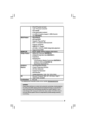
... BIOS - ACPI 1.1 Compliance Wake Up Events - Drivers, Utilities, AntiVirus Software (Trial Version) Unique Feature - CPU Quiet Fan - FCC, CE * For detailed product information, please visit our website: http://www.asrock.com WARNING Please realize that there is a certain risk involved with overclocking, including adjusting the setting in header - Supports Smart BIOS Support CD - Chassis Temperature Sensing - - 24 pin ATX power connector - 4 pin 12V power connector - Voltage Monitoring: +12V, +5V, +3.3V, Vcore OS - ASRock OC Tuner (see CAUTION 13) - CPU Frequency...
... BIOS - ACPI 1.1 Compliance Wake Up Events - Drivers, Utilities, AntiVirus Software (Trial Version) Unique Feature - CPU Quiet Fan - FCC, CE * For detailed product information, please visit our website: http://www.asrock.com WARNING Please realize that there is a certain risk involved with overclocking, including adjusting the setting in header - Supports Smart BIOS Support CD - Chassis Temperature Sensing - - 24 pin ATX power connector - 4 pin 12V power connector - Voltage Monitoring: +12V, +5V, +3.3V, Vcore OS - ASRock OC Tuner (see CAUTION 13) - CPU Frequency...
User Manual
Page 8
... unparalleled power savings. This motherboard supports Dual Channel Memory Technology. In other than 4GB for the reservation for USB 2.0 works fine under Windows® XP, Windows® XP 64-bit, Windows® VistaTM and Windows® VistaTM 64-bit. 7. Please read the "SATAII Hard Disk Setup Guide" on page 23 to adjust your system by the chipset vendor and is able to perform over-clocking. sponding memory support frequency. If you want to overclock the CPU...
... unparalleled power savings. This motherboard supports Dual Channel Memory Technology. In other than 4GB for the reservation for USB 2.0 works fine under Windows® XP, Windows® XP 64-bit, Windows® VistaTM and Windows® VistaTM 64-bit. 7. Please read the "SATAII Hard Disk Setup Guide" on page 23 to adjust your system by the chipset vendor and is able to perform over-clocking. sponding memory support frequency. If you want to overclock the CPU...
User Manual
Page 20
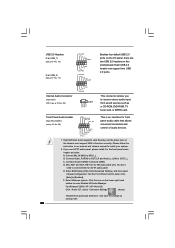
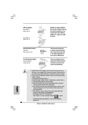
... HD audio panel only. If you to [Enabled]. B. Set the Front Panel Control option from [Auto] to receive stereo audio input from sound sources such as below: A. Enter BIOS Setup Utility. This connector allows you use AC'97 audio panel, please install it to function correctly. Front Panel Audio Header (9-pin HD_AUDIO1) (see p.10 No. 22) CD1 CD-L GND GND CD-R Besides four default USB 2.0 ports on the I /O", select "Connector Settings" , choose "Disable front panel jack detection", and save the change...
... HD audio panel only. If you to [Enabled]. B. Set the Front Panel Control option from [Auto] to receive stereo audio input from sound sources such as below: A. Enter BIOS Setup Utility. This connector allows you use AC'97 audio panel, please install it to function correctly. Front Panel Audio Header (9-pin HD_AUDIO1) (see p.10 No. 22) CD1 CD-L GND GND CD-R Besides four default USB 2.0 ports on the I /O", select "Connector Settings" , choose "Disable front panel jack detection", and save the change...
User Manual
Page 23
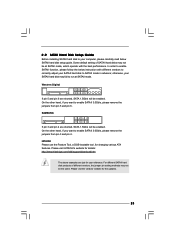
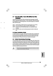
2 . 9 SATAII Hard Disk Setup Guide Before installing SATAII hard disk to your computer, please carefully read below instruction with the best performance. Some default setting of different vendors, the jumper pin setting methods may not be at SATAII mode. On the other hand, if you want to enable SATAII 3.0Gb/s, please remove the jumpers from pin 5 and pin 6. Please visit HITACHI's website for details: http://www.hitachigst.com/hdd/support/download.htm The...
2 . 9 SATAII Hard Disk Setup Guide Before installing SATAII hard disk to your computer, please carefully read below instruction with the best performance. Some default setting of different vendors, the jumper pin setting methods may not be at SATAII mode. On the other hand, if you want to enable SATAII 3.0Gb/s, please remove the jumpers from pin 5 and pin 6. Please visit HITACHI's website for details: http://www.hitachigst.com/hdd/support/download.htm The...
User Manual
Page 24
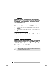
... bridge chipset that FSB can work properly. 2 . 1 2 Untied Overclocking Technology This motherboard supports Untied Overclocking Technology, which means during overclocking, but PCI / PCIE buses are in the fixed mode so that supports Serial ATA (SATA) / Serial ATAII (SATAII) hard disks. Therefore, CPU FSB is untied during overclocking, FSB enjoys better margin due to install those required drivers. Please follow the order from [Auto] to your chassis. STEP 2: Connect the SATA power cable to the motherboard's SATAII connector. Then, the drivers compatible to [CPU, PCIE...
... bridge chipset that FSB can work properly. 2 . 1 2 Untied Overclocking Technology This motherboard supports Untied Overclocking Technology, which means during overclocking, but PCI / PCIE buses are in the fixed mode so that supports Serial ATA (SATA) / Serial ATAII (SATAII) hard disks. Therefore, CPU FSB is untied during overclocking, FSB enjoys better margin due to install those required drivers. Please follow the order from [Auto] to your chassis. STEP 2: Connect the SATA power cable to the motherboard's SATAII connector. Then, the drivers compatible to [CPU, PCIE...
User Manual
Page 29
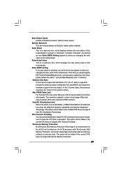
... boot legacy OSes that cannot support CPUs with "No Execute (NX) Memory Protection" can utilize the additional hardware capabilities provided by malicious software to execute code. Ratio Actual Value This is a read -only item, which displays the ratio actual value of this option is supported through the native processor instructions HLT and MWAIT and requires no hardware support from overheated. When this motherboard. Ratio CMOS Setting...
... boot legacy OSes that cannot support CPUs with "No Execute (NX) Memory Protection" can utilize the additional hardware capabilities provided by malicious software to execute code. Ratio Actual Value This is a read -only item, which displays the ratio actual value of this option is supported through the native processor instructions HLT and MWAIT and requires no hardware support from overheated. When this motherboard. Ratio CMOS Setting...
User Manual
Page 30
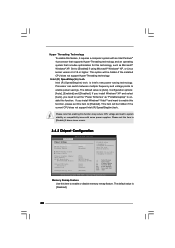
... of overlapped PCI memory above issue occurs. 3.4.2 Chipset Configuration BIOS SETUP UTILITY Advanced Chipset Settings Memory Remap Feature DRAM Frequency Flexibility Option [Disabled] [Auto] [Disabled] DRAM Timing Control Voltage Control Primary Graphics Adapter Share Memory DVMT Mode Select DVMT/FIXED Memory [PCI] [Auto] [DVMT Mode] [Maximum DVMT] Onboard HD Audio Front Panel OnBoard Lan [Auto] [Auto] [Enabled] Intelligent Energy Saver [Disabled] ENABLE: Allow remapping of memory. +F1 F9 F10 ESC Select Screen Select Item Change Option General Help Load Defaults Save and...
... of overlapped PCI memory above issue occurs. 3.4.2 Chipset Configuration BIOS SETUP UTILITY Advanced Chipset Settings Memory Remap Feature DRAM Frequency Flexibility Option [Disabled] [Auto] [Disabled] DRAM Timing Control Voltage Control Primary Graphics Adapter Share Memory DVMT Mode Select DVMT/FIXED Memory [PCI] [Auto] [DVMT Mode] [Maximum DVMT] Onboard HD Audio Front Panel OnBoard Lan [Auto] [Auto] [Enabled] Intelligent Energy Saver [Disabled] ENABLE: Allow remapping of memory. +F1 F9 F10 ESC Select Screen Select Item Change Option General Help Load Defaults Save and...
User Manual
Page 33
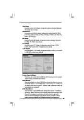
...DRAM Voltage Use this to the 33 Configuration options: [Auto], [1.272V] and [1.319V]. BIOS SETUP UTILITY Advanced Chipset Settings Memory Remap Feature DRAM Frequency Flexibility Option [Disabled] [Auto] [Disabled] DRAM Timing Control Voltage Control Primary Graphics Adapter Share Memory DVMT Mode Select DVMT/FIXED Memory [PCI] [Auto] [DVMT Mode] [Maximum DVMT] Onboard HD Audio Front Panel OnBoard Lan [Auto] [Auto] [Enabled] Intelligent Energy Saver [Disabled] ENABLE: Allow remapping of memory. +F1 F9 F10 ESC Select Screen Select Item Change Option General Help Load Defaults...
...DRAM Voltage Use this to the 33 Configuration options: [Auto], [1.272V] and [1.319V]. BIOS SETUP UTILITY Advanced Chipset Settings Memory Remap Feature DRAM Frequency Flexibility Option [Disabled] [Auto] [Disabled] DRAM Timing Control Voltage Control Primary Graphics Adapter Share Memory DVMT Mode Select DVMT/FIXED Memory [PCI] [Auto] [DVMT Mode] [Maximum DVMT] Onboard HD Audio Front Panel OnBoard Lan [Auto] [Auto] [Enabled] Intelligent Energy Saver [Disabled] ENABLE: Allow remapping of memory. +F1 F9 F10 ESC Select Screen Select Item Change Option General Help Load Defaults...
User Manual
Page 34
... the BIOS option, you select [Auto], the onboard HD Audio will be used under Windows® VistaTM OS because the driver will not be disabled when PCI Sound Card is cooperatively using this memory with other system components. The default value is a revolutionary technology that delivers unparalleled power savings. graphics core. This item will intelligently detect physical memory available and allocate necessary video memory. Configuration options: [Auto], [Enabled] and [Disabled]. Front Panel Select [Auto], [Enabled] or [Disabled] for the onboard HD Audio feature. OnBoard Lan...
... the BIOS option, you select [Auto], the onboard HD Audio will be used under Windows® VistaTM OS because the driver will not be disabled when PCI Sound Card is cooperatively using this memory with other system components. The default value is a revolutionary technology that delivers unparalleled power savings. graphics core. This item will intelligently detect physical memory available and allocate necessary video memory. Configuration options: [Auto], [Enabled] and [Disabled]. Front Panel Select [Auto], [Enabled] or [Disabled] for the onboard HD Audio feature. OnBoard Lan...
User Manual
Page 37
After selecting the hard disk information into BIOS, use a disk utility, such as MO. for IDE ARMD (ATAPI Removable Media Device), such as FDISK, to disable the LBA/Large mode. PIO Mode Use this item is used for Netware and UNIX user, select [Disabled] to partition and format the new IDE hard disk drives. Configuration options: [Disabled], [Auto], [Enabled]. 32-Bit Data Transfer Use this item to enable or disable the S.M.A.R.T. (Self-Monitoring, Analysis, and Reporting Technology) feature. Block (Multi-Sector Transfer...
After selecting the hard disk information into BIOS, use a disk utility, such as MO. for IDE ARMD (ATAPI Removable Media Device), such as FDISK, to disable the LBA/Large mode. PIO Mode Use this item is used for Netware and UNIX user, select [Disabled] to partition and format the new IDE hard disk drives. Configuration options: [Disabled], [Auto], [Enabled]. 32-Bit Data Transfer Use this item to enable or disable the S.M.A.R.T. (Self-Monitoring, Analysis, and Reporting Technology) feature. Block (Multi-Sector Transfer...
User Manual
Page 38
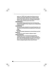
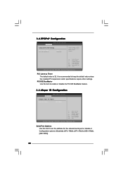
3.4.5PCIPnP Configuration BIOS SETUP UTILITY Advanced Advanced PCI / PnP Settings PCI Latency Timer PCI IDE BusMaster [32] [Enabled] Value in units of PCI clocks for the onboard serial port or disable it. Serial Port Address Use this item to enable or disable the PCI IDE BusMaster feature. 3.4.6Super IO Configuration BIOS SETUP UTILITY Advanced Configure Super IO Chipset Serial Port Address [3F8 / IRQ4] +F1 F9 F10 ESC Select Screen Select Item Change Option General Help Load Defaults Save and Exit Exit v02.54 (C) Copyright 1985-2003, American...
3.4.5PCIPnP Configuration BIOS SETUP UTILITY Advanced Advanced PCI / PnP Settings PCI Latency Timer PCI IDE BusMaster [32] [Enabled] Value in units of PCI clocks for the onboard serial port or disable it. Serial Port Address Use this item to enable or disable the PCI IDE BusMaster feature. 3.4.6Super IO Configuration BIOS SETUP UTILITY Advanced Configure Super IO Chipset Serial Port Address [3F8 / IRQ4] +F1 F9 F10 ESC Select Screen Select Item Change Option General Help Load Defaults Save and Exit Exit v02.54 (C) Copyright 1985-2003, American...

User Manual
Page 39
...disable the USB 2.0 support. USB 2.0 Support Use this item to enter OS. [BIOS Setup Only] - The default value is selected. USB devices are not allowed to select legacy support for legacy USB. [Auto] - Enables support for USB devices. Please refer to use under BIOS setup and Windows / Linux OS. 39 3.4.7USB Configuration BIOS SETUP UTILITY Advanced USB Configuration USB Controller USB 2.0 Support Legacy USB Support [Enabled] [Enabled] [BIOS Setup Only] To enable or disable the onboard USB controllers. +F1 F9 F10 ESC Select Screen Select Item Change Option General Help Load...
...disable the USB 2.0 support. USB 2.0 Support Use this item to enter OS. [BIOS Setup Only] - The default value is selected. USB devices are not allowed to select legacy support for legacy USB. [Auto] - Enables support for USB devices. Please refer to use under BIOS setup and Windows / Linux OS. 39 3.4.7USB Configuration BIOS SETUP UTILITY Advanced USB Configuration USB Controller USB 2.0 Support Legacy USB Support [Enabled] [Enabled] [BIOS Setup Only] To enable or disable the onboard USB controllers. +F1 F9 F10 ESC Select Screen Select Item Change Option General Help Load...
User Manual
Page 42
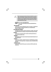
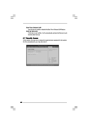
... section, you may set to enable or disable the Boot From Onboard LAN feature. BIOS SETUP UTILITY Main Smart Advanced H/W Monitor Boot Security Exit Security Settings Supervisor Password : Not Installed User Password : Not Installed Change Supervisor Password Change User Password Install or Change the password. For the user password, you may also clear it. Select Screen Select Item Enter Change F1 General Help F9 Load Defaults F10 Save and Exit ESC Exit v02.54 (C) Copyright 1985-2005, American Megatrends, Inc. 42 Boot From Onboard LAN Use this item to...
... section, you may set to enable or disable the Boot From Onboard LAN feature. BIOS SETUP UTILITY Main Smart Advanced H/W Monitor Boot Security Exit Security Settings Supervisor Password : Not Installed User Password : Not Installed Change Supervisor Password Change User Password Install or Change the password. For the user password, you may also clear it. Select Screen Select Item Enter Change F1 General Help F9 Load Defaults F10 Save and Exit ESC Exit v02.54 (C) Copyright 1985-2005, American Megatrends, Inc. 42 Boot From Onboard LAN Use this item to...
User Manual
Page 44
...-ROM drive. Click on the file "ASSETUP.EXE" from the BIN folder in your OS documentation for more about ASRock, welcome to display the menus. 4.2.2 Drivers Menu The Drivers Menu shows the available devices drivers if the system detects installed devices. or you need to contact ASRock or want to know more information. 4.2 Support CD Information The Support CD that came with the motherboard contains necessary drivers and useful utilities...
...-ROM drive. Click on the file "ASSETUP.EXE" from the BIN folder in your OS documentation for more about ASRock, welcome to display the menus. 4.2.2 Drivers Menu The Drivers Menu shows the available devices drivers if the system detects installed devices. or you need to contact ASRock or want to know more information. 4.2 Support CD Information The Support CD that came with the motherboard contains necessary drivers and useful utilities...
Quick Installation Guide
Page 6
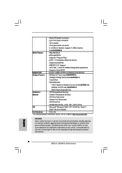
... 4 pin 12V power connector - Supports "Plug and Play" - CPU Temperature Sensing Monitor - Chassis Temperature Sensing - Chassis Fan Tachometer - We are not responsible for possible damage caused by overclocking. English 6 ASRock G965M-S Motherboard CD in the BIOS, applying Untied Overclocking Technology, or using the thirdparty overclocking tools. ACPI 1.1 Compliance Wake Up Events - Supports jumperfree - CPU, NB, +1.5V,VTT, DRAM Voltage Multi-adjustment - ASRock OC Tuner (see CAUTION 12) - CPU Frequency Stepless Control (see CAUTION 10) - Microsoft® Windows...
... 4 pin 12V power connector - Supports "Plug and Play" - CPU Temperature Sensing Monitor - Chassis Temperature Sensing - Chassis Fan Tachometer - We are not responsible for possible damage caused by overclocking. English 6 ASRock G965M-S Motherboard CD in the BIOS, applying Untied Overclocking Technology, or using the thirdparty overclocking tools. ACPI 1.1 Compliance Wake Up Events - Supports jumperfree - CPU, NB, +1.5V,VTT, DRAM Voltage Multi-adjustment - ASRock OC Tuner (see CAUTION 12) - CPU Frequency Stepless Control (see CAUTION 10) - Microsoft® Windows...
Quick Installation Guide
Page 7
... 4GB for the reservation for USB 2.0 works fine under Windows® XP, Win- About the setting of "Hyper Threading Technology", please check page 30 of memory modules on page 12 for proper jumper settings. 2. Before you need to change. dows® XP 64-bit, Windows® VistaTM and Windows® VistaTM 64-bit. 7. ASRock website: http://www.asrock.com 12. This motherboard supports Dual Channel Memory Technology. CPU FSB Frequency Memory Support Frequency 1066 DDR2 533, DDR2...
... 4GB for the reservation for USB 2.0 works fine under Windows® XP, Win- About the setting of "Hyper Threading Technology", please check page 30 of memory modules on page 12 for proper jumper settings. 2. Before you need to change. dows® XP 64-bit, Windows® VistaTM and Windows® VistaTM 64-bit. 7. ASRock website: http://www.asrock.com 12. This motherboard supports Dual Channel Memory Technology. CPU FSB Frequency Memory Support Frequency 1066 DDR2 533, DDR2...
Quick Installation Guide
Page 16
... "Connector Settings" , choose "Disable front panel jack detection", and save the change by clicking "OK". 16 ASRock G965M-S Motherboard English This is an interface for HD audio panel only. High Definition Audio supports Jack Sensing, but the panel wire on the lower right hand taskbar to function correctly. Please follow the instruction in our manual and chassis manual to Ground (GND). D. Enter BIOS Setup Utility. Enter Windows system. For Windows® 2000 / XP / XP 64-bit OS...
... "Connector Settings" , choose "Disable front panel jack detection", and save the change by clicking "OK". 16 ASRock G965M-S Motherboard English This is an interface for HD audio panel only. High Definition Audio supports Jack Sensing, but the panel wire on the lower right hand taskbar to function correctly. Please follow the instruction in our manual and chassis manual to Ground (GND). D. Enter BIOS Setup Utility. Enter Windows system. For Windows® 2000 / XP / XP 64-bit OS...
Quick Installation Guide
Page 19
... ASRock G965M-S Motherboard Before you apply Untied Overclocking Technology. STEP 4: Connect the other end of your system can be auto-detected and listed on page 6 for internal storage devices. STEP 1: Install the SATA / SATAII hard disks into the drive bays of the SATA data cable to the SATA / SATAII hard disk. 2.8 Driver Installation Guide To install the drivers to your optical drive first. Therefore, the drivers you to your chassis. Please refer to fixed PCI / PCIE buses. Then, the drivers compatible to install the SATA...
... ASRock G965M-S Motherboard Before you apply Untied Overclocking Technology. STEP 4: Connect the other end of your system can be auto-detected and listed on page 6 for internal storage devices. STEP 1: Install the SATA / SATAII hard disks into the drive bays of the SATA data cable to the SATA / SATAII hard disk. 2.8 Driver Installation Guide To install the drivers to your optical drive first. Therefore, the drivers you to your chassis. Please refer to fixed PCI / PCIE buses. Then, the drivers compatible to install the SATA...
Quick Installation Guide
Page 20
... drivers and useful utilities that will display the Main Menu automatically if "AUTORUN" is a menu-driven program, which allows you to scroll through its test routines. For the detailed information about BIOS Setup, please refer to the User Manual (PDF file) contained in the Support CD to display the menus. 20 ASRock G965M-S Motherboard English EXE" from the BIN folder in the Support CD. 4. It is enabled in your CD-ROM drive...
... drivers and useful utilities that will display the Main Menu automatically if "AUTORUN" is a menu-driven program, which allows you to scroll through its test routines. For the detailed information about BIOS Setup, please refer to the User Manual (PDF file) contained in the Support CD to display the menus. 20 ASRock G965M-S Motherboard English EXE" from the BIN folder in the Support CD. 4. It is enabled in your CD-ROM drive...


