User Manual
Page 3
... Guide 23 2.10 Serial ATA (SATA) / Serial ATAII (SATAII) Hard Disks Installation 24 2.11 Driver Installation Guide 24 2.12 Untied Overclocking Technology 24 3 BIOS SETUP UTILITY 25 3.1 Introduction 25 3.1.1 BIOS Menu Bar 25 3.1.2 Navigation Keys 26 3.2 Main Screen 26 3.3 Smart Screen 27 3.4 Advanced Screen 28 3.4.1 CPU Configuration 28 3.4.2 Chipset Configuration 30 3.4.3 ACPI...
... Guide 23 2.10 Serial ATA (SATA) / Serial ATAII (SATAII) Hard Disks Installation 24 2.11 Driver Installation Guide 24 2.12 Untied Overclocking Technology 24 3 BIOS SETUP UTILITY 25 3.1 Introduction 25 3.1.1 BIOS Menu Bar 25 3.1.2 Navigation Keys 26 3.2 Main Screen 26 3.3 Smart Screen 27 3.4 Advanced Screen 28 3.4.1 CPU Configuration 28 3.4.2 Chipset Configuration 30 3.4.3 ACPI...
User Manual
Page 5
..., 24.4 cm x 19.6 cm) ASRock G965M-S Quick Installation Guide ASRock G965M-S Support CD One 80-conductor Ultra ATA 66/100/133 IDE Ribbon Cable (Optional) One Serial ATA (SATA) Data Cable (Optional) One Serial ATA (SATA) HDD Power Cable (Optional) One I/O Panel Shield 5 Because the motherboard specifications and the BIOS software might be updated, the...
..., 24.4 cm x 19.6 cm) ASRock G965M-S Quick Installation Guide ASRock G965M-S Support CD One 80-conductor Ultra ATA 66/100/133 IDE Ribbon Cable (Optional) One Serial ATA (SATA) Data Cable (Optional) One Serial ATA (SATA) HDD Power Cable (Optional) One I/O Panel Shield 5 Because the motherboard specifications and the BIOS software might be updated, the...
User Manual
Page 7
... CE * For detailed product information, please visit our website: http://www.asrock.com WARNING Please realize that there is a certain risk involved with overclocking, including adjusting the setting in header - Supports Smart BIOS Support CD - CPU Fan Tachometer - It should be done at your ...system. Supports "Plug and Play" - CPU, NB, +1.5V,VTT, DRAM Voltage Multi-adjustment - ASRock U-COP (see CAUTION 12) - Overclocking may affect ...
... CE * For detailed product information, please visit our website: http://www.asrock.com WARNING Please realize that there is a certain risk involved with overclocking, including adjusting the setting in header - Supports Smart BIOS Support CD - CPU Fan Tachometer - It should be done at your ...system. Supports "Plug and Play" - CPU, NB, +1.5V,VTT, DRAM Voltage Multi-adjustment - ASRock U-COP (see CAUTION 12) - Overclocking may affect ...
User Manual
Page 10
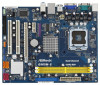
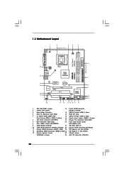
...Audio Connector: CD1 (Black) 11 Primary SATAII Connector (SATAII_1; Orange) 3 North Bridge Controller 15 USB 2.0 Header (USB6_7, Blue) 4 CPU Fan Connector (CPU_FAN1) 16 BIOS SPI Chip 5 2 x 240-pin DDR2 DIMM Slots 17 USB 2.0 Header (USB4_5, Blue) (Dual Channel: DDRII_1, DDRII_2; Yellow) 18 System Panel Header (PANEL1, Orange)... DDR2 800 VGA1 26 USB 2.0 T: USB2 B: USB3 ATX12V1 OC 800 1 USB 2.0 T: USB0 B: USB1 Top: RJ-45 25 Intel G965 Chipset G965M-S Top: Line In Center: Line Out Bottom: Mic In 24 23 22 21 LAN PHY Super IO CD1 AUDIO CODEC HD_AUDIO1 1 20 PCIE1 RoHS CMOS...
...Audio Connector: CD1 (Black) 11 Primary SATAII Connector (SATAII_1; Orange) 3 North Bridge Controller 15 USB 2.0 Header (USB6_7, Blue) 4 CPU Fan Connector (CPU_FAN1) 16 BIOS SPI Chip 5 2 x 240-pin DDR2 DIMM Slots 17 USB 2.0 Header (USB4_5, Blue) (Dual Channel: DDRII_1, DDRII_2; Yellow) 18 System Panel Header (PANEL1, Orange)... DDR2 800 VGA1 26 USB 2.0 T: USB2 B: USB3 ATX12V1 OC 800 1 USB 2.0 T: USB0 B: USB1 Top: RJ-45 25 Intel G965 Chipset G965M-S Top: Line In Center: Line Out Bottom: Mic In 24 23 22 21 LAN PHY Super IO CD1 AUDIO CODEC HD_AUDIO1 1 20 PCIE1 RoHS CMOS...
User Manual
Page 17
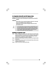
... slots: PCI slots are 2 PCI slots and 2 PCI Express slots on PCI Express VGA card to PCIE2 (PCIE x16 slot) and adjust the "Share Memory" BIOS option to [Enabled, 1MB] or [Enabled, 8MB], the onboard VGA will be enabled, and the primary screen will be onboard VGA. Before installing the expansion...
... slots: PCI slots are 2 PCI slots and 2 PCI Express slots on PCI Express VGA card to PCIE2 (PCIE x16 slot) and adjust the "Share Memory" BIOS option to [Enabled, 1MB] or [Enabled, 8MB], the onboard VGA will be enabled, and the primary screen will be onboard VGA. Before installing the expansion...
User Manual
Page 20
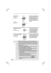
... chassis manual to OUT2_L. You don't need to the front panel audio header as a CD-ROM, DVD-ROM, TV tuner card, or MPEG card. Enter BIOS Setup Utility. Front Panel Audio Header (9-pin HD_AUDIO1) (see p.10 No. 22) CD1 CD-L GND GND CD-R Besides four default USB 2.0 ports on this motherboard...
... chassis manual to OUT2_L. You don't need to the front panel audio header as a CD-ROM, DVD-ROM, TV tuner card, or MPEG card. Enter BIOS Setup Utility. Front Panel Audio Header (9-pin HD_AUDIO1) (see p.10 No. 22) CD1 CD-L GND GND CD-R Besides four default USB 2.0 ports on this motherboard...
User Manual
Page 24
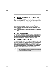
... on the support CD driver page. This section will guide you install can operate under a more stable overclocking environment. STEP 4: Connect the other end of BIOS setup to set the selection from up to bottom side to install those required drivers. Therefore, CPU FSB is untied during overclocking, but PCI / PCIE...
... on the support CD driver page. This section will guide you install can operate under a more stable overclocking environment. STEP 4: Connect the other end of BIOS setup to set the selection from up to bottom side to install those required drivers. Therefore, CPU FSB is untied during overclocking, but PCI / PCIE...

User Manual
Page 25
... off and then back on. erating System Security To set up the default system device to locate and load the Op- You may run the BIOS SETUP UTILITY when you see on the system chassis. You may not exactly match what you start up the security features Exit To exit the... your system. The SPI Memory on the menu bar, and then press to get into the sub screen. 25 Chapter 3 BIOS SETUP UTILITY 3.1 Introduction This section explains how to use the BIOS SETUP UTILITY to configure your screen. 3.1.1BIOS Menu Bar The top of the screen has a menu bar with its test...
... off and then back on. erating System Security To set up the default system device to locate and load the Op- You may run the BIOS SETUP UTILITY when you see on the system chassis. You may not exactly match what you start up the security features Exit To exit the... your system. The SPI Memory on the menu bar, and then press to get into the sub screen. 25 Chapter 3 BIOS SETUP UTILITY 3.1 Introduction This section explains how to use the BIOS SETUP UTILITY to configure your screen. 3.1.1BIOS Menu Bar The top of the screen has a menu bar with its test...
User Manual
Page 26
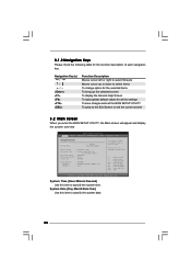
...jump to the Exit Screen or exit the current screen 3.2 Main Screen When you enter the BIOS SETUP UTILITY, the Main screen will appear and display the system overview BIOS SETUP UTILITY Main Smart Advanced H/W Monitor Boot Security Exit System Overview System Time System Date [14...:00:09] [Fri 02/20/2009] BIOS Version : G965M-S P1.00 Processor Type : Genuine Intel (R) CPU @ 1.86GHz (64bit) Processor Speed : 1866MHz Microcode Update : 6F4/0 Cache Size : 2048KB Total Memory ...
...jump to the Exit Screen or exit the current screen 3.2 Main Screen When you enter the BIOS SETUP UTILITY, the Main screen will appear and display the system overview BIOS SETUP UTILITY Main Smart Advanced H/W Monitor Boot Security Exit System Overview System Time System Date [14...:00:09] [Fri 02/20/2009] BIOS Version : G965M-S P1.00 Processor Type : Genuine Intel (R) CPU @ 1.86GHz (64bit) Processor Speed : 1866MHz Microcode Update : 6F4/0 Cache Size : 2048KB Total Memory ...
User Manual
Page 27
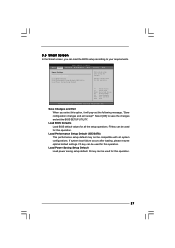
... Select Item Enter Go to save the changes and exit the BIOS SETUP UTILITY. If system boot failure occurs after saving the changes. F10 key can load the BIOS setup according to your requirements. BIOS SETUP UTILITY Main Smart Advanced H/W Monitor Boot Security Exit Smart Settings... Save Changes and Exit Load BIOS Defaults Load Performance Setup Default (IDE/SATA) Load Power Saving Setup...
... Select Item Enter Go to save the changes and exit the BIOS SETUP UTILITY. If system boot failure occurs after saving the changes. F10 key can load the BIOS setup according to your requirements. BIOS SETUP UTILITY Main Smart Advanced H/W Monitor Boot Security Exit Smart Settings... Save Changes and Exit Load BIOS Defaults Load Performance Setup Default (IDE/SATA) Load Power Saving Setup...

User Manual
Page 28
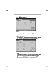
..., ACPI Configuration, IDE Configuration, PCIPnP Configuration, SuperIO Configuration, and USB Configuration. Overclock Mode Use this option to malfunction. 3.4.1 CPU Configuration BIOS SETUP UTILITY Advanced CPU Configuration Overclock Mode CPU Frequency (MHz) PCIE Frequency (MHz) Boot Failure Guard Spread Spectrum [Auto] [266] [100.... CPU Frequency (MHz) Use this section may cause the system to adjust PCIE frequency. 28 BIOS SETUP UTILITY Main Smart Advanced H/W Monitor Boot Security Exit Advanced Settings WARNING : Setting wrong values in this option to malfunction.
..., ACPI Configuration, IDE Configuration, PCIPnP Configuration, SuperIO Configuration, and USB Configuration. Overclock Mode Use this option to malfunction. 3.4.1 CPU Configuration BIOS SETUP UTILITY Advanced CPU Configuration Overclock Mode CPU Frequency (MHz) PCIE Frequency (MHz) Boot Failure Guard Spread Spectrum [Auto] [266] [100.... CPU Frequency (MHz) Use this section may cause the system to adjust PCIE frequency. 28 BIOS SETUP UTILITY Main Smart Advanced H/W Monitor Boot Security Exit Advanced Settings WARNING : Setting wrong values in this option to malfunction.
User Manual
Page 30
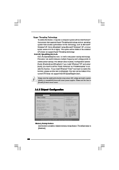
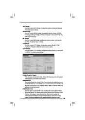
... you need to set the "Power Schemes" as Microsoft® Windows® XP. Please set this item to [Disable] if above issue occurs. 3.4.2 Chipset Configuration BIOS SETUP UTILITY Advanced Chipset Settings Memory Remap Feature DRAM Frequency Flexibility Option [Disabled] [Auto] [Disabled] DRAM Timing Control Voltage Control Primary Graphics Adapter Share Memory...
... you need to set the "Power Schemes" as Microsoft® Windows® XP. Please set this item to [Disable] if above issue occurs. 3.4.2 Chipset Configuration BIOS SETUP UTILITY Advanced Chipset Settings Memory Remap Feature DRAM Frequency Flexibility Option [Disabled] [Auto] [Disabled] DRAM Timing Control Voltage Control Primary Graphics Adapter Share Memory...
User Manual
Page 31
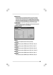
... clocks for TRFC. Min: 9. You may change according to [Enabled]. Min: 3. DRAM tRFC This controls the number of DRAM clocks for TRRD. DRAM Timing Control BIOS SETUP UTILITY Advanced DRAM Timing Control Current Setting : 4-4-4-12-28-4-2 DRAM tCL [Auto] DRAM tRCD [Auto] DRAM tRP [Auto] DRAM tRAS [Auto] DRAM tRFC [Auto...
... clocks for TRFC. Min: 9. You may change according to [Enabled]. Min: 3. DRAM tRFC This controls the number of DRAM clocks for TRRD. DRAM Timing Control BIOS SETUP UTILITY Advanced DRAM Timing Control Current Setting : 4-4-4-12-28-4-2 DRAM tCL [Auto] DRAM tRCD [Auto] DRAM tRP [Auto] DRAM tRAS [Auto] DRAM tRFC [Auto...
User Manual
Page 32
...)], [2.50X (55)], [2.75X (66)], [3.00X (77)], [3.25X (88)], [3.50X (99)], [3.75X (AA)], [4.00X (BB)], [4.25X (CC)], [4.50X (DD)], [4.75X (EE)] and [5.00X (FF)]. Voltage Control BIOS SETUP UTILITY Advanced Voltage Control CPU Voltage DRAM Voltage NB Voltage VTT Offset Voltage +1.5V Voltage [Auto] [Auto] [Auto] [Auto] [Auto] Options Auto Manual 32...
...)], [2.50X (55)], [2.75X (66)], [3.00X (77)], [3.25X (88)], [3.50X (99)], [3.75X (AA)], [4.00X (BB)], [4.25X (CC)], [4.50X (DD)], [4.75X (EE)] and [5.00X (FF)]. Voltage Control BIOS SETUP UTILITY Advanced Voltage Control CPU Voltage DRAM Voltage NB Voltage VTT Offset Voltage +1.5V Voltage [Auto] [Auto] [Auto] [Auto] [Auto] Options Auto Manual 32...
User Manual
Page 33
.... Configuration options: [Fixed Mode] and [DVMT Mode]. CPU Voltage Use this to select +1.5V Voltage. The default value is [Auto]. Configuration options: [Auto] and [Manual]. BIOS SETUP UTILITY Advanced Chipset Settings Memory Remap Feature DRAM Frequency Flexibility Option [Disabled] [Auto] [Disabled] DRAM Timing Control Voltage Control Primary Graphics Adapter Share Memory...
.... Configuration options: [Fixed Mode] and [DVMT Mode]. CPU Voltage Use this to select +1.5V Voltage. The default value is [Auto]. Configuration options: [Auto] and [Manual]. BIOS SETUP UTILITY Advanced Chipset Settings Memory Remap Feature DRAM Frequency Flexibility Option [Disabled] [Auto] [Disabled] DRAM Timing Control Voltage Control Primary Graphics Adapter Share Memory...
User Manual
Page 34
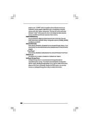
... you set this function. 34 Configuration options: [128MB], [256MB] and [Maximum DVMT]. If you want to enable or disable the "OnBoard Lan" feature. Besides the BIOS option, you to enable this function, please set DVMT Mode Select as [DVMT Mode]. Intelligent Energy Saver Intelligent Energy Saver is [Disabled].
... you set this function. 34 Configuration options: [128MB], [256MB] and [Maximum DVMT]. If you want to enable or disable the "OnBoard Lan" feature. Besides the BIOS option, you to enable this function, please set DVMT Mode Select as [DVMT Mode]. Intelligent Energy Saver Intelligent Energy Saver is [Disabled].
User Manual
Page 35
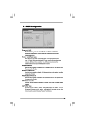
...-to boot up when the power recovers. If [Power On] is selected, the AC/Power resumes and the system starts to -RAM feature. 3.4.3ACPI Configuration BIOS SETUP UTILITY Advanced ACPI Configuration Suspend To RAM Restore on the system. PS/2 Keyboard Power On Use this feature if the system supports it. ACPI...
...-to boot up when the power recovers. If [Power On] is selected, the AC/Power resumes and the system starts to -RAM feature. 3.4.3ACPI Configuration BIOS SETUP UTILITY Advanced ACPI Configuration Suspend To RAM Restore on the system. PS/2 Keyboard Power On Use this feature if the system supports it. ACPI...
User Manual
Page 36
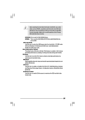
... you specify. TYPE Use this item to disable the use the "Primary IDE Master" as the example in the following instruction. 3.4.4 IDE Configuration BIOS SETUP UTILITY Advanced IDE Configuration SATAII Configuration [Enhanced] SATAII 1 SATAII 2 SATAII 3 SATAII 4 IDE1 Master IDE1 Slave [Hard Disk] [Not Detected...Not Installed]: Select [Not Installed] to configure the type of the IDE device that you install legacy OS (Windows® NT). BIOS SETUP UTILITY Advanced Primary IDE Master Device Vendor Size LBA Mode Block Mode PIO Mode Async DMA Ultra DMA S.M.A.R.T. Type LBA/Large Mode...
... you specify. TYPE Use this item to disable the use the "Primary IDE Master" as the example in the following instruction. 3.4.4 IDE Configuration BIOS SETUP UTILITY Advanced IDE Configuration SATAII Configuration [Enhanced] SATAII 1 SATAII 2 SATAII 3 SATAII 4 IDE1 Master IDE1 Slave [Hard Disk] [Not Detected...Not Installed]: Select [Not Installed] to configure the type of the IDE device that you install legacy OS (Windows® NT). BIOS SETUP UTILITY Advanced Primary IDE Master Device Vendor Size LBA Mode Block Mode PIO Mode Async DMA Ultra DMA S.M.A.R.T. Type LBA/Large Mode...
User Manual
Page 37
.../DVD drives. [ARMD]: This is enabled, it will enhance hard disk performance by optimizing the hard disk timing. After selecting the hard disk information into BIOS, use a disk utility, such as MO. This is [Auto]. S.M.A.R.T. Block (Multi-Sector Transfer) The default value of the Primary IDE hard disk drives to active...
.../DVD drives. [ARMD]: This is enabled, it will enhance hard disk performance by optimizing the hard disk timing. After selecting the hard disk information into BIOS, use a disk utility, such as MO. This is [Auto]. S.M.A.R.T. Block (Multi-Sector Transfer) The default value of the Primary IDE hard disk drives to active...
User Manual
Page 38
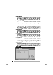
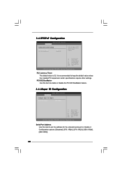
... settings. PCI Latency Timer The default value is recommended to enable or disable the PCI IDE BusMaster feature. 3.4.6Super IO Configuration BIOS SETUP UTILITY Advanced Configure Super IO Chipset Serial Port Address [3F8 / IRQ4] +F1 F9 F10 ESC Select Screen Select Item ..., American Megatrends, Inc. Configuration options: [Disabled], [3F8 / IRQ4], [2F8 / IRQ3], [3E8 / IRQ4], [2E8 / IRQ3]. 38 3.4.5PCIPnP Configuration BIOS SETUP UTILITY Advanced Advanced PCI / PnP Settings PCI Latency Timer PCI IDE BusMaster [32] [Enabled] Value in units of PCI clocks for the onboard serial...
... settings. PCI Latency Timer The default value is recommended to enable or disable the PCI IDE BusMaster feature. 3.4.6Super IO Configuration BIOS SETUP UTILITY Advanced Configure Super IO Chipset Serial Port Address [3F8 / IRQ4] +F1 F9 F10 ESC Select Screen Select Item ..., American Megatrends, Inc. Configuration options: [Disabled], [3F8 / IRQ4], [2F8 / IRQ3], [3E8 / IRQ4], [2E8 / IRQ3]. 38 3.4.5PCIPnP Configuration BIOS SETUP UTILITY Advanced Advanced PCI / PnP Settings PCI Latency Timer PCI IDE BusMaster [32] [Enabled] Value in units of PCI clocks for the onboard serial...


