User Manual
Page 11
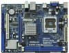
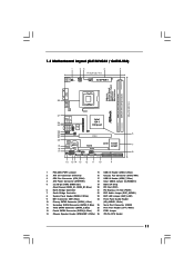
... (SATAII_1; Blue) (HD_AUDIO1, White) 11 Secondary SATAII Connector (SATAII_2; Blue) 27 FSB1 Jumper 14 Chassis Speaker Header (SPEAKER 1, White) 28 775-Pin CPU Socket 11 1.3 Motherboard Layout (G41M-VGS3 / G41M-VS3) 1 23 4 5 17.0cm (6.7 in) PS2 Mouse PS2 Keyboard 1 PS2_USB_PWR1 ATX12V2 CPU_FAN1 1 COM1 FSB1333 ErP/EuP Ready Designed in Taipei DDR3 1333 Dual Channel...
... (SATAII_1; Blue) (HD_AUDIO1, White) 11 Secondary SATAII Connector (SATAII_2; Blue) 27 FSB1 Jumper 14 Chassis Speaker Header (SPEAKER 1, White) 28 775-Pin CPU Socket 11 1.3 Motherboard Layout (G41M-VGS3 / G41M-VS3) 1 23 4 5 17.0cm (6.7 in) PS2 Mouse PS2 Keyboard 1 PS2_USB_PWR1 ATX12V2 CPU_FAN1 1 COM1 FSB1333 ErP/EuP Ready Designed in Taipei DDR3 1333 Dual Channel...
User Manual
Page 14
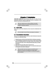
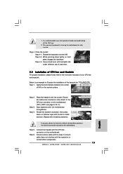
... installing or removing the motherboard. To avoid damaging the motherboard components due to the motherboard, peripherals, and/or components. 14 Chapter 2 Installation G41M-VGS3 / G41M-VS3 is detached from the wall socket before you install motherboard components or change any component. 2. Failure to do so may damage the motherboard. 2.2 Pre-installation Precautions Take note...
... installing or removing the motherboard. To avoid damaging the motherboard components due to the motherboard, peripherals, and/or components. 14 Chapter 2 Installation G41M-VGS3 / G41M-VS3 is detached from the wall socket before you install motherboard components or change any component. 2. Failure to do so may damage the motherboard. 2.2 Pre-installation Precautions Take note...

User Manual
Page 15
... 2-1. Locate Pin1 and the two orientation key notches. Otherwise, the CPU will be seriously damaged. Step 1-2. Orient the CPU with black lines. Open the socket: CPU Marked Corner Step 1-1. Step 1-3. Rotate the load plate to fully open position at approximately 100 degrees. black line black line Step 2-2. Step 1. ... tab. Do not force to fully open position at approximately 135 degrees. Rotate the load lever to insert the CPU into the socket, please check if the CPU surface is unclean or if there is found. Hold the CPU by depressing down and out on the...
... 2-1. Locate Pin1 and the two orientation key notches. Otherwise, the CPU will be seriously damaged. Step 1-2. Orient the CPU with black lines. Open the socket: CPU Marked Corner Step 1-1. Step 1-3. Rotate the load plate to fully open position at approximately 100 degrees. black line black line Step 2-2. Step 1. ... tab. Do not force to fully open position at approximately 135 degrees. Rotate the load lever to insert the CPU into the socket, please check if the CPU surface is unclean or if there is found. Hold the CPU by depressing down and out on the...
User Manual
Page 16
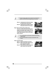
.... 1. This cap must be placed if returning the motherboard for after service. Secure load lever with the two alignment keys of the socket. Step 2-3. Step 4. Close the socket: Step 4-1. For proper inserting, please ensure to match the two orientation key notches of the CPU with load plate tab under retention ...tab of load lever. 16 Carefully place the CPU into the socket by using a purely vertical motion. Step 3. Remove PnP Cap (Pick and Place Cap): Use your left hand index finger and thumb to support ...
.... 1. This cap must be placed if returning the motherboard for after service. Secure load lever with the two alignment keys of the socket. Step 2-3. Step 4. Close the socket: Step 4-1. For proper inserting, please ensure to match the two orientation key notches of the CPU with load plate tab under retention ...tab of load lever. 16 Carefully place the CPU into the socket by using a purely vertical motion. Step 3. Remove PnP Cap (Pick and Place Cap): Use your left hand index finger and thumb to support ...
User Manual
Page 17
...LAND CPU. Step 1. Rotate the fastener clockwise, then press down the fasteners without rotating them clockwise, the heatsink cannot be secured on the socket surface. Step 6. Before you installed the heatsink, you press down on fastener caps with fan operation or contact other . Below is equipped ...with 775-Pin socket that the CPU and the heatsink are oriented on side closest to the CPU_FAN connector (CPU_FAN1, see page 11, No. 3). Step 2. Step ...
...LAND CPU. Step 1. Rotate the fastener clockwise, then press down the fasteners without rotating them clockwise, the heatsink cannot be secured on the socket surface. Step 6. Before you installed the heatsink, you press down on fastener caps with fan operation or contact other . Below is equipped ...with 775-Pin socket that the CPU and the heatsink are oriented on side closest to the CPU_FAN connector (CPU_FAN1, see page 11, No. 3). Step 2. Step ...
Quick Installation Guide
Page 2
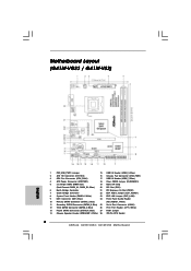
Motherboard Layout (G41M-VGS3 / G41M-VS3) English 1 PS2_USB_PWR1 Jumper 15 USB 2.0 Header (USB4_5, Blue) 2 ATX 12V Connector (ATX12V2) 16 Chassis Fan Connector (CHA_FAN1) 3 CPU Fan Connector (CPU_FAN1) 17 USB 2.0 Header ... Print Port Header (LPT1, White) 13 Fourth SATAII Connector (SATAII_4; Blue) 27 FSB1 Jumper 14 Chassis Speaker Header (SPEAKER 1, White) 28 775-Pin CPU Socket 2 ASRock G41M-VGS3 / G41M-VS3 Motherboard Blue) (HD_AUDIO1, White) 11 Secondary SATAII Connector (SATAII_2; Blue) 25 Serial Port Connector (COM1) 12 Third SATAII Connector (SATAII_3; Blue) 20 PCI ...
Motherboard Layout (G41M-VGS3 / G41M-VS3) English 1 PS2_USB_PWR1 Jumper 15 USB 2.0 Header (USB4_5, Blue) 2 ATX 12V Connector (ATX12V2) 16 Chassis Fan Connector (CHA_FAN1) 3 CPU Fan Connector (CPU_FAN1) 17 USB 2.0 Header ... Print Port Header (LPT1, White) 13 Fourth SATAII Connector (SATAII_4; Blue) 27 FSB1 Jumper 14 Chassis Speaker Header (SPEAKER 1, White) 28 775-Pin CPU Socket 2 ASRock G41M-VGS3 / G41M-VS3 Motherboard Blue) (HD_AUDIO1, White) 11 Secondary SATAII Connector (SATAII_2; Blue) 25 Serial Port Connector (COM1) 12 Third SATAII Connector (SATAII_3; Blue) 20 PCI ...
Quick Installation Guide
Page 11
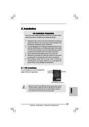
...to do so may damage the motherboard. 2.1 CPU Installation For the installation of the following precautions before touching any bent pin on the socket. To avoid damaging the motherboard components due to the motherboard, peripherals, and/or components. 2. When placing screws into the screw holes to...CPU into the socket if above situation is any component. Do not force to the chassis, please do not touch the ICs. 4. Hold components by the edges and do not over-tighten the screws! Otherwise, the CPU will be seriously damaged. 11 ASRock G41M-VGS3 / G41M-VS3 Motherboard English ...
...to do so may damage the motherboard. 2.1 CPU Installation For the installation of the following precautions before touching any bent pin on the socket. To avoid damaging the motherboard components due to the motherboard, peripherals, and/or components. 2. When placing screws into the screw holes to...CPU into the socket if above situation is any component. Do not force to the chassis, please do not touch the ICs. 4. Hold components by the edges and do not over-tighten the screws! Otherwise, the CPU will be seriously damaged. 11 ASRock G41M-VGS3 / G41M-VS3 Motherboard English ...
Quick Installation Guide
Page 12
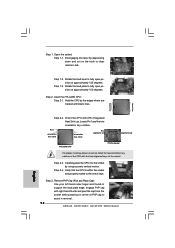
... out on center of the CPU with right hand thumb and peel the cap from the socket while pressing on the hook to assist in removal. 12 ASRock G41M-VGS3 / G41M-VS3 Motherboard Step 2. Pin1 orientation key notch orientation key notch Pin1 alignment key alignment key 775-...LAND CPU 775-Pin Socket For proper inserting, please ensure to fully open position at approximately 135 degrees. ...
... out on center of the CPU with right hand thumb and peel the cap from the socket while pressing on the hook to assist in removal. 12 ASRock G41M-VGS3 / G41M-VS3 Motherboard Step 2. Pin1 orientation key notch orientation key notch Pin1 alignment key alignment key 775-...LAND CPU 775-Pin Socket For proper inserting, please ensure to fully open position at approximately 135 degrees. ...
Quick Installation Guide
Page 13
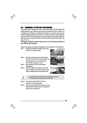
... to install and lock. Step 6. This cap must be secured on fastener caps with fan operation or contact other components. 13 ASRock G41M-VGS3 / G41M-VS3 Motherboard English Step 3. Place the heatsink onto the socket. Align fasteners with remaining fasteners. Rotate the fastener clockwise, then press down the fasteners without rotating them clockwise, the heatsink...
... to install and lock. Step 6. This cap must be secured on fastener caps with fan operation or contact other components. 13 ASRock G41M-VGS3 / G41M-VS3 Motherboard English Step 3. Place the heatsink onto the socket. Align fasteners with remaining fasteners. Rotate the fastener clockwise, then press down the fasteners without rotating them clockwise, the heatsink...
