
User Manual
Page 3
... Guide 25 2.10 Serial ATA (SATA) / Serial ATAII (SATAII) Hard Disks Installation 26 2.11 Driver Installation Guide 26 2.12 Untied Overclocking Technology 26 3 BIOS SETUP UTILITY 27 3.1 Introduction 27 3.1.1 BIOS Menu Bar 27 3.1.2 Navigation Keys 28 3.2 Main Screen 28 3.3 Smart Screen 29 3.4 Advanced Screen 30 3.4.1 CPU Configuration 30 3.4.2 Chipset Configuration 32 3.4.3 ACPI...
... Guide 25 2.10 Serial ATA (SATA) / Serial ATAII (SATAII) Hard Disks Installation 26 2.11 Driver Installation Guide 26 2.12 Untied Overclocking Technology 26 3 BIOS SETUP UTILITY 27 3.1 Introduction 27 3.1.1 BIOS Menu Bar 27 3.1.2 Navigation Keys 28 3.2 Main Screen 28 3.3 Smart Screen 29 3.4 Advanced Screen 30 3.4.1 CPU Configuration 30 3.4.2 Chipset Configuration 32 3.4.3 ACPI...

User Manual
Page 5
... If you are using. www.asrock.com/support/index.asp 1.1 Package Contents ASRock G41M-LE/H Motherboard (Micro ATX Form Factor: 9.6-in x 8.6-in, 24.4 cm x 21.8 cm) ASRock G41M-LE/H Quick Installation Guide ASRock G41M-LE/H Support CD One 80-conductor Ultra ATA 66/100 IDE Ribbon Cable One Serial ...to BIOS setup and information of the motherboard and step-by-step guide to the hardware installation. Chapter 1: Introduction Thank you for specific information about the model you require technical support related to this motherboard, please visit our website for purchasing ASRock G41M-LE/H ...
... If you are using. www.asrock.com/support/index.asp 1.1 Package Contents ASRock G41M-LE/H Motherboard (Micro ATX Form Factor: 9.6-in x 8.6-in, 24.4 cm x 21.8 cm) ASRock G41M-LE/H Quick Installation Guide ASRock G41M-LE/H Support CD One 80-conductor Ultra ATA 66/100 IDE Ribbon Cable One Serial ...to BIOS setup and information of the motherboard and step-by-step guide to the hardware installation. Chapter 1: Introduction Thank you for specific information about the model you require technical support related to this motherboard, please visit our website for purchasing ASRock G41M-LE/H ...

User Manual
Page 7
.../ Line in header - AMI Legal BIOS - Supports "Plug and Play" - Supports Smart BIOS Support CD - Boot Failure Guard (B.F.G.) Hardware - Chassis Temperature Sensing - Chassis Fan Tachometer - Voltage Monitoring: +12V, +5V, +3.3V, CPU Vcore OS - AMBIOS 2.3.1 Support - Drivers, Utilities, AntiVirus Software (Trial Version) Unique Feature - ASRock OC Tuner (see CAUTION 15) - ASRock U-COP (see CAUTION 12...
.../ Line in header - AMI Legal BIOS - Supports "Plug and Play" - Supports Smart BIOS Support CD - Boot Failure Guard (B.F.G.) Hardware - Chassis Temperature Sensing - Chassis Fan Tachometer - Voltage Monitoring: +12V, +5V, +3.3V, CPU Vcore OS - AMBIOS 2.3.1 Support - Drivers, Utilities, AntiVirus Software (Trial Version) Unique Feature - ASRock OC Tuner (see CAUTION 15) - ASRock U-COP (see CAUTION 12...

User Manual
Page 8
... to page 10 for details. 4. For Windows® XP 64-bit and Windows® VistaTM 64-bit with overclocking, including adjusting the setting in the BIOS, applying Untied Overclocking Technology, or using the thirdparty overclocking tools. Overclocking may be done at your system. This motherboard supports native FSB1333/1066/800 MHz...
... to page 10 for details. 4. For Windows® XP 64-bit and Windows® VistaTM 64-bit with overclocking, including adjusting the setting in the BIOS, applying Untied Overclocking Technology, or using the thirdparty overclocking tools. Overclocking may be done at your system. This motherboard supports native FSB1333/1066/800 MHz...

User Manual
Page 10
... UNIVERSAL WEA 10 1 . 3 Minimum Hardware Requirement for the minimum hardware requirement. CPU VGA Memory Suggested OS Playback Software Intel® E5200 (BIOS option PAVP Lite mode disabled) Intel® E1200 (BIOS option PAVP Lite mode enabled) G41 onboard DX10 VGA DDR2 800 1GB x 2 Windows® VistaTM or Windows® VistaTM 64 CyberLink...
... UNIVERSAL WEA 10 1 . 3 Minimum Hardware Requirement for the minimum hardware requirement. CPU VGA Memory Suggested OS Playback Software Intel® E5200 (BIOS option PAVP Lite mode disabled) Intel® E1200 (BIOS option PAVP Lite mode enabled) G41 onboard DX10 VGA DDR2 800 1GB x 2 Windows® VistaTM or Windows® VistaTM 64 CyberLink...

User Manual
Page 11
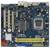
...Bottom: MIC IN LAN Gigabit LAN PHY PCIE1 Intel G41 Chipset RoHS RoHS G41M-LE IDE1 CHA_FAN1 PCIE2 Super I/O PCI1 AUDIO CODEC CD1 HD_AUDIO1 1 1 LPT1 PCI2 FLOPPY1 25 24 23 22 CMOS Battery CLRCMOS1 1 8Mb BIOS USB4_5 1 USB6_7 1 Intel ICH7 SPEAKER1 1 PLED PWRBTN PANEL1 1 HDLED...9 10 11 12 13 14 15 1 PS2_USB_PWR1 Jumper 17 Secondary SATAII Connector 2 ATX 12V Connector (ATX12V1) (SATAII_2; Red) 3 CPU Fan Connector (CPU_FAN1) 18 BIOS SPI Chip 4 FSB3 Jumper 19 USB 2.0 Header (USB6_7, Blue) 5 775-Pin CPU Socket 20 USB 2.0 Header (USB4_5, Blue) 6 2 x 240-pin ...
...Bottom: MIC IN LAN Gigabit LAN PHY PCIE1 Intel G41 Chipset RoHS RoHS G41M-LE IDE1 CHA_FAN1 PCIE2 Super I/O PCI1 AUDIO CODEC CD1 HD_AUDIO1 1 1 LPT1 PCI2 FLOPPY1 25 24 23 22 CMOS Battery CLRCMOS1 1 8Mb BIOS USB4_5 1 USB6_7 1 Intel ICH7 SPEAKER1 1 PLED PWRBTN PANEL1 1 HDLED...9 10 11 12 13 14 15 1 PS2_USB_PWR1 Jumper 17 Secondary SATAII Connector 2 ATX 12V Connector (ATX12V1) (SATAII_2; Red) 3 CPU Fan Connector (CPU_FAN1) 18 BIOS SPI Chip 4 FSB3 Jumper 19 USB 2.0 Header (USB6_7, Blue) 5 775-Pin CPU Socket 20 USB 2.0 Header (USB4_5, Blue) 6 2 x 240-pin ...

User Manual
Page 18
... x1 slot) is used for the card before you install the add-on PCI Express VGA card to PCIE2 (PCIE x16 slot) and adjust the BIOS options "Primary Graphics Adapter" to [Onboard] and "Share Memory" to [Auto], then the onboard VGA will be enabled, and the primary screen will be onboard...
... x1 slot) is used for the card before you install the add-on PCI Express VGA card to PCIE2 (PCIE x16 slot) and adjust the BIOS options "Primary Graphics Adapter" to [Onboard] and "Share Memory" to [Auto], then the onboard VGA will be enabled, and the primary screen will be onboard...

User Manual
Page 20
... 1_2 FSB3 FSB2 4_5 1_2 FSB1 FSB1: 1-2 FSB2: 4-5 FSB3: 1-2 Overclocking Setting: When you mount a FSB800 or FSB1066 CPU, and try to overclock to FSB1333 (by BIOS setting) you need to be overclocked very high.
... 1_2 FSB3 FSB2 4_5 1_2 FSB1 FSB1: 1-2 FSB2: 4-5 FSB3: 1-2 Overclocking Setting: When you mount a FSB800 or FSB1066 CPU, and try to overclock to FSB1333 (by BIOS setting) you need to be overclocked very high.
User Manual
Page 23
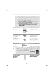
... DUMMY +5V GND +12V CHA_FAN_SPEED Please connect the chassis speaker to this motherboard, please connect it to Ground (GND). Connect Mic_IN (MIC) to OUT2_L. Enter BIOS Setup Utility. If you use AC'97 audio panel, please install it to this motherboard provides 4-Pin CPU fan (Quiet Fan) support, the 3-Pin CPU...
... DUMMY +5V GND +12V CHA_FAN_SPEED Please connect the chassis speaker to this motherboard, please connect it to Ground (GND). Connect Mic_IN (MIC) to OUT2_L. Enter BIOS Setup Utility. If you use AC'97 audio panel, please install it to this motherboard provides 4-Pin CPU fan (Quiet Fan) support, the 3-Pin CPU...

User Manual
Page 26
STEP 1: Install the SATA / SATAII hard disks into the drive bays of BIOS setup to set the selection from up to bottom side to [Manual]. Then, the drivers compatible to your system, please insert the support CD to ...
STEP 1: Install the SATA / SATAII hard disks into the drive bays of BIOS setup to set the selection from up to bottom side to [Manual]. Then, the drivers compatible to your system, please insert the support CD to ...

User Manual
Page 27
... Use < > key or < > key to choose among the selections on the menu bar, and then press to enter the BIOS SETUP UTILITY, otherwise, POST will continue with the following BIOS setup screens and descriptions are for reference purpose only, and they may also restart by pressing the reset button on the...system by pressing + + , or by turning the system off and then back on. You may not exactly match what you wish to configure your screen. 3.1.1 BIOS Menu Bar The top of the screen has a menu bar with its test routines. Please press during the Power-On-Self-Test (POST) to get...
... Use < > key or < > key to choose among the selections on the menu bar, and then press to enter the BIOS SETUP UTILITY, otherwise, POST will continue with the following BIOS setup screens and descriptions are for reference purpose only, and they may also restart by pressing the reset button on the...system by pressing + + , or by turning the system off and then back on. You may not exactly match what you wish to configure your screen. 3.1.1 BIOS Menu Bar The top of the screen has a menu bar with its test routines. Please press during the Power-On-Self-Test (POST) to get...

User Manual
Page 28
... UTILITY Main Smart Advanced H/W Monitor Boot Security Exit System Overview System Time System Date [14:00:09] [Thu 10/02/2008] BIOS Version : G41M-LE P1.00 Processor Type : Intel(R) CPU 3.20GHz (64bit) Processor Speed : 3200MHz Microcode Update : F64/4 Cache Size : 4096KB Total Memory DDRII1 DDRII2 : 1024MB with 128MB shared...this item to specify the system date. 28 3.1.2Navigation Keys Please check the following table for all the settings To save changes and exit the BIOS SETUP UTILITY To jump to the Exit Screen or exit the current screen 3.2 Main Screen When you enter the...
... UTILITY Main Smart Advanced H/W Monitor Boot Security Exit System Overview System Time System Date [14:00:09] [Thu 10/02/2008] BIOS Version : G41M-LE P1.00 Processor Type : Intel(R) CPU 3.20GHz (64bit) Processor Speed : 3200MHz Microcode Update : F64/4 Cache Size : 4096KB Total Memory DDRII1 DDRII2 : 1024MB with 128MB shared...this item to specify the system date. 28 3.1.2Navigation Keys Please check the following table for all the settings To save changes and exit the BIOS SETUP UTILITY To jump to the Exit Screen or exit the current screen 3.2 Main Screen When you enter the...

User Manual
Page 29
...Default (IDE/SATA) Load Power Saving Setup Default Exit system setup after loading, please resume optimal default settings. F9 key can load the BIOS setup according to your requirements. F5 key can be used for all system configurations. 3.3 Smart Screen In the Smart screen, you select this... operation. 29 Select Screen Select Item Enter Go to save the changes and exit the BIOS SETUP UTILITY. F6 key can be compatible with all the setup questions. Load Performance Setup Default (IDE/SATA) This performance setup default may...
...Default (IDE/SATA) Load Power Saving Setup Default Exit system setup after loading, please resume optimal default settings. F9 key can load the BIOS setup according to your requirements. F5 key can be used for all system configurations. 3.3 Smart Screen In the Smart screen, you select this... operation. 29 Select Screen Select Item Enter Go to save the changes and exit the BIOS SETUP UTILITY. F6 key can be compatible with all the setup questions. Load Performance Setup Default (IDE/SATA) This performance setup default may...
User Manual
Page 30
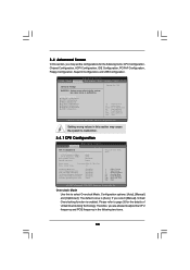
...Configuration, SuperIO Configuration, and USB Configuration. Setting wrong values in below sections may cause the system to malfunction. 3.4.1 CPU Configuration BIOS SETUP UTILITY Advanced CPU Configuration Overclock Mode CPU Frequency (MHz) PCIE Frequency (MHz) Boot Failure Guard Spread Spectrum [Auto] ... [Auto] Ratio Status Ratio Actual Value Unlocked (Min: 12, Max: 16) 16 Enhanced Halt State Intel Virtualization tech. BIOS SETUP UTILITY Main Smart Advanced H/W Monitor Boot Security Exit Advanced Settings WARNING : Setting wrong values in this to select Overclock ...
...Configuration, SuperIO Configuration, and USB Configuration. Setting wrong values in below sections may cause the system to malfunction. 3.4.1 CPU Configuration BIOS SETUP UTILITY Advanced CPU Configuration Overclock Mode CPU Frequency (MHz) PCIE Frequency (MHz) Boot Failure Guard Spread Spectrum [Auto] ... [Auto] Ratio Status Ratio Actual Value Unlocked (Min: 12, Max: 16) 16 Enhanced Halt State Intel Virtualization tech. BIOS SETUP UTILITY Main Smart Advanced H/W Monitor Boot Security Exit Advanced Settings WARNING : Setting wrong values in this to select Overclock ...
User Manual
Page 32
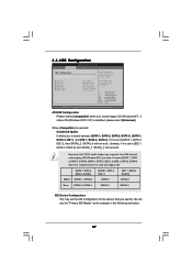
... "Portable/Laptop" to enable this item to page 8 for memory compatibility when it is [Disabled]. Please refer to [Disable] if above issue occurs. 3.4.2 Chipset Configuration BIOS SETUP UTILITY Advanced Chipset Configuration Memory Remap Feature [Disabled] DRAM Frequency [Auto] Flexibility Option [Disabled] Standard Memory Info : 5-5-5-15-36-5-3-3-3 DRAM tCL [Auto] DRAM tRCD...
... "Portable/Laptop" to enable this item to page 8 for memory compatibility when it is [Disabled]. Please refer to [Disable] if above issue occurs. 3.4.2 Chipset Configuration BIOS SETUP UTILITY Advanced Chipset Configuration Memory Remap Feature [Disabled] DRAM Frequency [Auto] Flexibility Option [Disabled] Standard Memory Info : 5-5-5-15-36-5-3-3-3 DRAM tCL [Auto] DRAM tRCD...

User Manual
Page 35
...]. Configuration options: [Auto], [0.67 x Vtt], [0.65 x Vtt], [0.63 x Vtt] and [0.615 x Vtt]. The default value is a revolutionary technology that delivers unparalleled power savings. Besides the BIOS option, you can also choose our Intelligent Energy Saver utility to enable this item to enable or disable the "OnBoard Lan" feature. If you to...
...]. Configuration options: [Auto], [0.67 x Vtt], [0.65 x Vtt], [0.63 x Vtt] and [0.615 x Vtt]. The default value is a revolutionary technology that delivers unparalleled power savings. Besides the BIOS option, you can also choose our Intelligent Energy Saver utility to enable this item to enable or disable the "OnBoard Lan" feature. If you to...
User Manual
Page 36
... enable or disable PCI devices to submit Windows® VistaTM certification. 36 The default value is selected, the AC/Power remains off mode. 3.4.3ACPI Configuration BIOS SETUP UTILITY Advanced ACPI Configuration Suspend To RAM Restore on the system from the power-soft-off when the power recovers. PCI Devices Power On...
... enable or disable PCI devices to submit Windows® VistaTM certification. 36 The default value is selected, the AC/Power remains off mode. 3.4.3ACPI Configuration BIOS SETUP UTILITY Advanced ACPI Configuration Suspend To RAM Restore on the system from the power-soft-off when the power recovers. PCI Devices Power On...
User Manual
Page 37
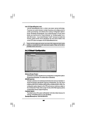
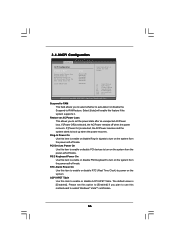
... (Windows NT), you have to choose [SATA 1, SATA 2, SATA 3, SATA 4], [SATA 1, SATA 3, IDE 1], or [IDE 1, SATA 2, SATA 4] when the installed device is used . 3.4.4IDE Configuration BIOS SETUP UTILITY Advanced IDE Configuration ATA/IDE Configuration SATAII_1 SATAII_2 SATAII_3 SATAII_4 IDE1 Master IDE1 Slave [Enhanced] [Hard Disk] [Not Detected] [Not Detected] [Not Detected...
... (Windows NT), you have to choose [SATA 1, SATA 2, SATA 3, SATA 4], [SATA 1, SATA 3, IDE 1], or [IDE 1, SATA 2, SATA 4] when the installed device is used . 3.4.4IDE Configuration BIOS SETUP UTILITY Advanced IDE Configuration ATA/IDE Configuration SATAII_1 SATAII_2 SATAII_3 SATAII_4 IDE1 Master IDE1 Slave [Enhanced] [Hard Disk] [Not Detected] [Not Detected] [Not Detected...
User Manual
Page 38
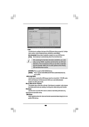
After selecting the hard disk information into BIOS, use of IDE device. [Auto]: Select [Auto] to active. [CD/DVD]: This is used for Netware and UNIX user, select [Disabled] to the system. +F1 ... write or read data from the hard disk. If this item to enhance hard disk performance by reading or writing more data during each transfer. BIOS SETUP UTILITY Advanced Primary IDE Master Device Vendor Size LBA Mode Block Mode PIO Mode Async DMA Ultra DMA S.M.A.R.T. LBA/Large Mode Use this item...
After selecting the hard disk information into BIOS, use of IDE device. [Auto]: Select [Auto] to active. [CD/DVD]: This is used for Netware and UNIX user, select [Disabled] to the system. +F1 ... write or read data from the hard disk. If this item to enhance hard disk performance by reading or writing more data during each transfer. BIOS SETUP UTILITY Advanced Primary IDE Master Device Vendor Size LBA Mode Block Mode PIO Mode Async DMA Ultra DMA S.M.A.R.T. LBA/Large Mode Use this item...

User Manual
Page 39
... the S.M.A.R.T. (Self-Monitoring, Analysis, and Reporting Technology) feature. PCI IDE BusMaster Use this item to maximize the IDE hard disk data transfer rate. 3.4.5 PCIPnP Configuration BIOS SETUP UTILITY Advanced Advanced PCI / PnP Settings PCI Latency Timer PCI IDE BusMaster [32] [Enabled] Value in units of PCI clocks for PCI device latency...
... the S.M.A.R.T. (Self-Monitoring, Analysis, and Reporting Technology) feature. PCI IDE BusMaster Use this item to maximize the IDE hard disk data transfer rate. 3.4.5 PCIPnP Configuration BIOS SETUP UTILITY Advanced Advanced PCI / PnP Settings PCI Latency Timer PCI IDE BusMaster [32] [Enabled] Value in units of PCI clocks for PCI device latency...


